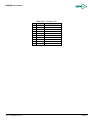
1
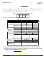
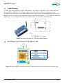
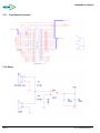
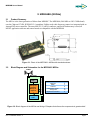
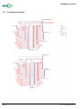
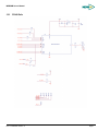
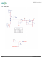
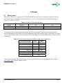
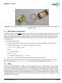
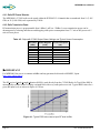
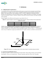
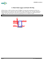
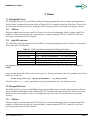
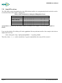
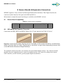
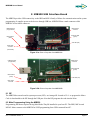
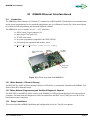
Powerful Sensing Solutions for a Better Life Mote Processor Radio & Mote Interface Boards User Manual Document Part Number: 7430-0021-09 Rev A MEMSIC, Inc., 1759 McCarthy Blvd, Milpitas, CA 95035 Tel: 408-964-9700, Fax: 408-854-7702 email: [email protected], website: www.memsic.com © 2010 MEMSIC, Inc. All rights reserved. Information in this document is subject to change without notice. MEMSIC, MoteWorks, IRIS, MICA, TrueMesh and XMesh are the trademarks of MEMSIC, Inc. Other product and trade names are trademarks or registered trademarks of their respective holders. MPR/MIB User’s Manual Table of Contents 1 Introduction.............................................................................................................................1 2 XM2110 (IRIS)........................................................................................................................2 3 4 5 2.1 Product Summary ...........................................................................................................3 2.2 Block Diagram and Schematics for the XM2110 / IRIS ................................................3 MPR2400 (MICAz).................................................................................................................5 3.1 Product Summary ...........................................................................................................5 3.2 Block Diagram and Schematics for the MPR2400 / MICAz .........................................5 Power .......................................................................................................................................9 4.1 Battery Power .................................................................................................................9 4.2 External Power .............................................................................................................10 4.3 MICAz Battery Voltage Monitor .................................................................................11 4.4 MICAz..........................................................................................................................11 4.5 IRIS ..............................................................................................................................13 Antennas ..............................................................................................................................14 5.1 Radio/Antenna Considerations.....................................................................................14 5.2 Connectors for the IRIS Whip Antennas......................................................................14 6 Flash Data Logger and Serial ID Chip ...............................................................................16 7 Fuses.......................................................................................................................................17 8 9 10 7.1 ATmega128L Fuses .....................................................................................................17 7.2 ATmega1281 Fuses......................................................................................................17 Sensor Boards & Expansion Connectors............................................................................19 8.1 Sensor Board Compatibility .........................................................................................19 8.2 IRIS and MICAz Expansion Connector .......................................................................19 MIB520 USB Interface Board .............................................................................................21 9.1 ISP ................................................................................................................................21 9.2 Mote Programming Using the MIB520........................................................................21 9.3 MIB520 Use .................................................................................................................22 9.4 Reset .............................................................................................................................22 9.5 JTAG ............................................................................................................................22 9.6 Power............................................................................................................................22 9.7 USB Interface ...............................................................................................................22 9.8 51-Pin Mote Connector Interface .................................................................................23 MIB600 Ethernet Interface Board ...................................................................................25 Doc. # 7430-0021-09 Rev. A Page 1 MPR/MIB User’s Manual 10.1 Introduction...............................................................................................................25 10.2 Setup / Installation ....................................................................................................25 10.3 MIB600 Use..............................................................................................................27 10.4 JTAG.........................................................................................................................28 11 Appendix A: 10/100 Base-T Cabling Standards .............................................................30 12 Appendix B. Warranty and Support Information..........................................................31 12.1 Customer Service......................................................................................................31 12.2 Contact Directory......................................................................................................31 12.3 Return Procedure ......................................................................................................31 12.4 Warranty ...................................................................................................................32 Page 2 Doc. # 7430-0021-09 Rev. A MPR/MIB User’s Manual About This Document The following annotations have been used to provide additional information. ; NOTE Note provides additional information about the topic. ; EXAMPLE Examples are given throughout the manual to help the reader understand the terminology. 3 IMPORTANT This symbol defines items that have significant meaning to the user 0 WARNING The user should pay particular attention to this symbol. It means there is a chance that physical harm could happen to either the person or the equipment. The following paragraph heading formatting is used in this manual: 1 Heading 1 1.1 Heading 2 1.1.1 Heading 3 This document also uses different body text fonts (listed in Table 0-1) to help you distinguish between names of files, commands to be typed, and output coming from the computer. Table 0-1. Font types used in this document. Font Type Usage Courier New Normal Sample code and screen output Courier New Bold Commands to be typed by the user Times New Roman Italic TinyOS files names, directory names Franklin Medium Condensed Doc. # 7430-0021-09 Rev. A Text labels in GUIs Page 3 MPR/MIB User’s Manual 1 Introduction This User’s Manual describes the hardware features of the Mote Processor Radio (MPR) platforms and Mote Interface Boards (MIB) for network base stations and programming interfaces. It is intended for understanding and leveraging MEMSIC’s Smart Dust hardware design in real-world sensor network, smart RFID, and ubiquitous computing applications. Table 1-1 below lists the models in this Manual. Table 1-1. This User’s Manual covers these MPR models. MPR 2400 XM2110 LPR2400 (MICAz) (IRIS) (LOTUS) The Table 1-2 below summarizes the main features of each Mote. Table 1-2. Mote Product Summary Mote Hardware Platform IRIS MICAz LOTUS Models (as of April 2005) XM2110 MPR2400 LPR2400 ATMega1281 ATMega128L ARM7 Cortex M3 Chip Type MCU 7.37 MHz, 8 bit 100MHz, 32 bit 128 32MBpbytes Program Memory (kB) SRAM (kB) 8 4 Sensor Board Interface 7, 0 V to 3 V input 10-Bit ADC 2 UART DIO, I2C Other interfaces Chip RF Transceiver (Radio) Type RF231 2400 250 MMCX N/A AT45DB014B W25Q64CVSSI SPI Connection Type Size Default power source CC2420 Max. Data Rate (kbits/sec) Chip Flash Data Logger Memory RF230 Radio Frequency (MHz) Antenna Connector 64Kbytes 51 pin Type 512 64Mb AA, 2× This Manual is not a software guide to programming the motes in TinyOS/nesC, nor is it a guide to pre-built software packages that run on top of the Motes. The following two resources are available regarding software: MoteWorks Getting Started Guide by MEMSIC, Inc. available on the WSN Kit CDROM or the MEMSIC web site at www.memsic.com under Support>User’s Manuals. The TinyOS web site at http://www.tinyos.net/ Doc. # 7430-0021-09 Rev. A Page 1 MPR/MIB User’s Manual Page 2 Doc. # 7430-0021-09 Rev. A MPR/MIB User’s Manual 2.1 Product Summary The IRIS is the latest generation of Motes from MEMSIC. The XM2110 (2400 MHz to 2483.5 MHz band) uses the Atmel RF230, IEEE 802.15.4 compliant, ZigBee ready radio frequency transceiver integrated with an Atmega1281 micro-controller. These enhancements provide up to three times improved radio range and twice the program memory over previous generation MICA Motes. The same MICA family, 51 pin I/O connector, and serial flash memory is used; all application software and sensor boards are compatible with the XM2110. Figure 2-1. Photo of the XM2110—IRIS with standard antenna 2.2 Block Diagram and Schematics for the XM2110 / IRIS Feature Batteries Radio Antenna Data Flash Logger Atmega1281 Expansion Connector Chapter 6 7 8 9 10 11 Figure 2-2. Block diagram of the IRIS and listing of Chapters that discuss the components in greater detail. Doc. # 7430-0021-09 Rev. A Page 3 MPR/MIB User’s Manual 2.2.1 51-pin Expansion Connector 2.2.2 Battery Page 4 Doc. # 7430-0021-09 Rev. A MPR/MIB User’s Manual 3 MPR2400 (MICAz) 3.1 Product Summary The MICAz is the latest generation of Motes from MEMSIC. The MPR2400 (2400 MHz to 2483.5 MHz band) uses the Chipcon CC2420, IEEE 802.15.4 compliant, ZigBee ready radio frequency transceiver integrated with an Atmega128L micro-controller. The same MICA2, 51 pin I/O connector, and serial flash memory is used; all MICA2 application software and sensor boards are compatible with the MPR2400. Figure 3-1. Photo of the MPR2400—MICAz with standard antenna. 3.2 Block Diagram and Schematics for the MPR2400 / MICAz Antenna MMCX connector ATMega128L μcontroller Analog I/O Digital I/O Feature Batteries Radio Antenna Data Flash Logger Atmega128 Expansion Connector Chapter 6 7 8 9 10 11 LEDs CC2420 DSSS Radio 51-Pin Expansion Connector Logger Flash Figure 3-2. Block diagram of the MICAz and listing of Chapters that discuss the components in greater detail. Doc. # 7430-0021-09 Rev. A Page 5 MPR/MIB User’s Manual 3.2.1 Page 6 51-pin Expansion Connector Doc. # 7430-0021-09 Rev. A MPR/MIB User’s Manual 3.2.2 CC2420 Radio Doc. # 7430-0021-09 Rev. A Page 7 MPR/MIB User’s Manual 3.2.3 Page 8 Battery, ADC1 Doc. # 7430-0021-09 Rev. A MPR/MIB User’s Manual 4 Power 4.1 Battery Power All motes are designed for battery power. The IRIS and MICAz form factors are designed to match up with two AA batteries; however any battery combination (AAA, C, D, etc., cells) can be used provided that the output is between 2.7 VDC to 3.6 VDC. Table 4-1. Batteries for the Mote Platforms. Mote Hardware Platform IRIS MICAz Standard Battery (# required) AA (2) AA (2) Typical Battery Capacity (mAhr) 2000, Alkaline 2000, Alkaline Practical Operating Voltage Range (V) 3.6 to 2.7 3.6 to 2.7 Care should be used in selecting the battery and its capacity to match the energy needs of the motes and their required operating span. Also make sure that the temperature range and associated capacity degradation are looked at prior to deployment. Table 4-2 below provides some useful guidance on current consumption of various system components. Table 4-2. Current Requirements for the Motes under Various Operations. Operating Current (mA) IRIS MICAz 8 (7.37 MHz) 12 (7.37 MHz) 0.008 0.010 Radio, receive 16 19.7 Radio, transmit (1 mW power) 17 17 0.001 0.001 Processor, full operation Processor, sleep Radio, sleep Serial flash memory, write 15 Serial flash memory, read 4 Serial flash memory, sleep 0.002 Table 4-3 below provides some useful guidance on how to predict battery life. The spreadsheet can be found at www.memsic.com under the Support section. Doc. # 7430-0021-09 Rev. A Page 9 MPR/MIB User’s Manual Table 4-3. Estimate of battery life operation for a Mote. SYSTEM SPECIFICATIONS Currents Example Duty Cycle Processor Current (full operation) 8 mA 1 Current sleep 8 μA 99 Current in receive 8 mA 0.75 Current transmit 12 mA 0.25 Current sleep 2 μA 99 Write 15 mA 0 Read 4 mA 0 Sleep 2 μA 100 Sensor Board Current (full operation) 5 mA 1 Current sleep 5 μA 99 Radio Logger Memory Computed mA-hr used each hour Processor 0.0879 Radio 0.0920 Logger Memory 0.0020 Sensor Board 0.0550 Total current (mA-hr) used 0.2369 Computed battery life vs. battery size Battery Capacity (mA-hr) Battery Life (months) 250 1.45 1000 5.78 3000 17.35 ; NOTE: In most Mote applications, the processor and radio run for a brief period of time, followed by a sleep cycle. During sleep, current consumption is in the micro-amps as opposed to milli-amps. This results in very low-current draw the majority of the time, and short duration spikes while processing, receiving, and transmitting data. This method extends battery life; however, due to the current surges, it reduces specified battery capacity. Battery capacity is typically specified by the manufacturer for a constant nominal current drawn. 4.2 External Power The MICAz can be externally powered through either: 1. The 51-pin connector will supply power and ground to the unit. Refer to connector description. 2. The 2-pin Molex connector. Molex part number 53261-0290, Digi-Key part number WM1753-ND. (See Figure 4-4 below.) Page 10 Doc. # 7430-0021-09 Rev. A MPR/MIB User’s Manual Figure 4-4. Photo of using the Molex connector to attach the AA battery pack. Photo courtesy of Nick Sitar, UC Berkeley, 2004. 4.3 MICAz Battery Voltage Monitor The MICAz has an accurate internal voltage reference that can be used to measure battery voltage (Vbatt). Since the eight-channel ADC on the ATMega128L uses the battery voltage as a full scale reference, the ADC full scale voltage value changes as the battery voltage changes. In order to track the battery voltage, the precision voltage reference (band gap reference) is monitored to determine the ADC full-scale (ADC_FS) voltage span which corresponds to Vbatt. To compute the battery voltage: 1. Program the application code to measure ADC channel 30 – the Internal Bandgap Voltage reference. 2. Compute battery voltage, Vbatt, from ADC reading (ADC_Count) by: Vbatt = Vref × ADC _ FS ADC _ Count where: Vbatt = Battery voltage ADC_FS = 1024 Vref = Internal voltage reference = 1.223 volts ADC_Count = Data from the ADC measurement of Internal Voltage reference The TinyOS component VoltageM.nc can be wired into an application to provide this measurement capability. The reserved keyword TOS_ADC_VOLTAGE_PORT is mapped to ADC Channel 30 in the MICAz. 4.4 MICAz The radio used by the MPR2600 is an IEEE 802.15.4 compliant RF transceiver designed for low-power and lowvoltage wireless applications. It uses Chipcon’s CC2420 radio that employs O-QPSK (“offset quadrature phase shift keying”) with half sine pulse shaping. The 802.15.4 radio includes a DSSS (digital direct sequence spread spectrum) baseband modem providing a spreading gain of 9 dB and an effective data rate of 250 kbps. The radio is a highly integrated solution for wireless communication in the 2.4 GHz unlicensed ISM band. It complies with worldwide regulations covered by ETSI EN 300 328 and EN 300 440 class 2 (Europe), FCC CFR47 Part 15 (US) and ARIB STD-T66 (Japan). Doc. # 7430-0021-09 Rev. A Page 11 MPR/MIB User’s Manual 4.4.1 Radio RF Channel Selection The MPR2600’s CC2420 radio can be tuned within the IEEE 802.15.4 channels that are numbered from 11 (2.405 GHz) to 26 (2.480 GHz) each separated by 5 MHz. 4.4.2 Radio Transmission Power RF transmission power is programmable from 0 dBm (1 mW) to –25dBm. Lower transmission power can be advantageous by reducing interference and dropping radio power consumption from 17.5 mA at full power to 8.5 mA at lowest power. Table 4-5. Chipcon® CC2420 Output Power Settings and Typical Current Consumption RF Power (dBm) Power Register (code) 0 -1 -3 -5 -7 -10 -15 -25 31 27 23 19 15 11 7 3 Current Consumption (mA) 17.4 16.5 15.2 13.9 12.5 11.2 9.9 8.5 3 IMPORTANT For MPR2400J, the power is constant at 0dBm and any questions be directed to MEMSIC, Japan. http://www.xbow.com/jp. The RF received signal strength indication (RSSI) is read directly from the CC2420 Radio. In TinyOS the RSSI is automatically returned in the TOSMsg->strength field with every radio packet received. Typical RSSI values for a given RF input level are shown in Figure 4-1 below. Figure 4-1. Typical RSSI value versus input RF level in dBm. Page 12 Doc. # 7430-0021-09 Rev. A MPR/MIB User’s Manual 4.5 IRIS The radio used by the IRIS is an IEEE 802.15.4 compliant RF transceiver designed for low-power and low-voltage wireless applications. It uses Atmel’s AT86RF230 radio that employs O-QPSK (“offset quadrature phase shift keying”) with half sine pulse shaping. The 802.15.4 radio includes a DSSS (digital direct sequence spread spectrum) baseband modem providing a spreading gain of 9 dB and an effective data rate of 250 kbps. The radio is a highly integrated solution for wireless communication in the 2.4 GHz unlicensed ISM band. It complies with worldwide regulations covered by ETSI EN 300 328 and EN 300 440 class 2 (Europe), FCC CFR47 Part 15 (US) and ARIB STD-T66 (Japan). 4.5.1 Radio RF Channel Selection The M2110’s Atmel radio can be tuned within the IEEE 802.15.4 channels that are numbered from 11 (2.405 GHz) to 26 (2.480 GHz) each separated by 5 MHz. 4.5.2 Radio Transmission Power RF transmission power is programmable from 3 dBm to –17.2 dBm. Lower transmission power can be advantageous by reducing interference and dropping radio power consumption. Table 4-6. Atmel® AT86RF230 Output Power Settings RF Power (dBm) Power Register (code) 3.0 2.6 2.1 1.6 1.1 0.5 -0.2 -1.2 -2.2 -3.2 -4.2 -5.2 -7.2 -9.2 -12.2 -17.2 0 1 2 3 4 5 6 7 8 9 10 11 12 13 14 15 The RF received signal strength indication (RSSI) is read directly from the AT86RF230 Radio and sent with every radio packet received. Doc. # 7430-0021-09 Rev. A Page 13 MPR/MIB User’s Manual 5 Antennas 5.1 Radio/Antenna Considerations Care should be taken to provide an antenna that provides proper coverage for the environment expected. Range and performance are strongly affected by choice of antenna and antenna placement within the environment. In addition, care must be taken to ensure compliance with FCC article 15 regulations for intentional radiators. Because of its small physical size, the usual antenna chosen is a length of insulated wire one-quarter wavelength long for the frequency of interest. This type of antenna is often called a monopole antenna, and its gain is ground plane dependent. Antenna lengths for the different radio frequencies are provided in Table 5-1. Table 5-1. Antenna lengths for quarter wavelength whip antennas. The part numbers for the connectorized antennas are listed. Name Model MICAz IRIS MPR2400 XM2110 (2400 MHz) Whip Antenna Length (inches) 1.2 1.2 MEMSIC Part No. 8060-0011-04 8060-0011-04 Antennas are also available from Linx Technologies, such as part number ANT-433-PW-QW for 433 MHz and ANT-916-PW-QW for 916 MHz. These antennas are terminated in a coax pigtail, and must have an MMCX connector installed. They also function best with a ground plane installed, as shown in Figure 5-2. The ground plane can be a layer of aluminum or copper tape attached to the lid of a plastic enclosure, or the lid of a metal enclosure. NUT MAKES CONTACT WITH GROUND PLANE METALLIC GROUND PLANE 1/2 WAVELENGTH RECOMMENDED Figure 5-2. Illustration of an antenna option for the motes using a Linx antenna and ground plane. 5.2 Connectors for the IRIS Whip Antennas The IRIS has an MMCX connector for attaching an external antenna. These mating connectors can be purchased from Digi-Key. There are two manufacturers—Johnson Components and Hirose Electric Ltd. The mating Page 14 Doc. # 7430-0021-09 Rev. A MPR/MIB User’s Manual connectors come in straight and right angle. They also support two different standard varieties of Coaxial cable— RG178 /U and RG 316/U. There are also other vendors who sell MMCX to SMA conversion cables. Table 5-3. Johnson Components’ MMCX mating connectors* Type Coax Digi-Key PN Johnson PN Straight Plug RG178/U J589-ND 135-3402-001 Straight Plug RG316/U J590-ND 135-3403-001 Right Angle RG178/U J593-ND 135-3402-101 Right Angle RG316/U J594-ND 135-3403-101 Right Angle RG 316 DS J595-ND 135-3404-101 * These connectors require the following hand crimp and die set (Digi-Key part # / Johnson part #): a) Hand crimp (J572-ND / 140-0000-952), b) Die (JD604-ND / 140-0000-953). Table 5-4. Hirose MMCX connectors. Doc. # 7430-0021-09 Rev. A Type Coax Digi-Key PN Hirose PN Straight Plug RG178/U H3224-ND MMCX-J-178B/U Right Angle RG178/U H3221-ND MMCX-LP-178B/U Right Angle RG316/U H3222-ND MMCX-LP-316/U Page 15 MPR/MIB User’s Manual 6 Flash Data Logger and Serial ID Chip All Motes feature a 4-Mbit serial flash (Atmel AT45DB041) for storing data, measurements, and other userdefined information. It is connected to one of the USART on the ATmega128L/1281. This chip is supported in TinyOS which uses this chip as micro file system. The serial flash device supports over 100,000 measurement readings. This chip is also used for over-the-air reprogramming services available in TinyOS. ; NOTE: This device consumes 15 mA of current when writing data. VCC USART1_TXD USART_CLK 1 2 3 FLASH_CS 4 SI SO 8 USART1_RXD SCK RST CS WP 5 x Atmega AT45DB041 Page 16 Doc. # 7430-0021-09 Rev. A MPR/MIB User’s Manual 7 Fuses 7.1 ATmega128L Fuses The ATMega128L processor on the MICAz Motes has many programmable fuses to control various parameters. Refer to Atmel’s technical information for the ATMega128L for a complete discussion of the fuses. There are few fuses that users should be aware of as setting these fuses incorrectly will cause the unit to not operate correctly. 7.1.1 JTAG fuse This fuse enables users to use the Atmel JTAG pod for in-circuit code debugging. Units are shipped with JTAG enabled. As discussed in the previous section on battery voltage monitoring, if JTAG is enabled, it will cause inaccurate measurements on ADC channel 7. 7.1.2 Using UISP to set fuses The UISP utility used to download code to the MICAz on a programming board can also be used to set and unset fuses of the Atmel® ATMega128. Table 7-1. UISP Commands for Setting the ATmega128’s Fuses. Action Disable JTAG fuse Enable JTAG fuse Enable native 128 mode Use internal clock Use external clock Command uisp -dprog=<programmer> --wr_fuse_h=0xD9 uisp -dprog=<programmer> --wr_fuse_h=0x19 uisp -dprog=<programmer> --wr_fuse_e=ff uisp -dprog=<programmer> --wr_fuse_l=0xc4 uisp -dprog=<programmer> --wr_fuse_l=0xff <programmer> is the device you are using to interface to the Mote from a computer. The current option is EPRB for a MIB600. Users can also edit the file called profile in the cygwin/etc/ directory and enter an alias. One example is this alias to disable the JTAG fuse: alias fuse_dis="uisp -dprog=<programmer> --wr_fuse_h=0xD9" Therefore, when fuse_dis and is entered into a Cygwin command line, the script will be executed. 7.2 ATmega1281 Fuses The ATMega1281V processor on the IRIS has many programmable fuses to control various parameters. Refer to Atmel’s technical information for the ATMega1281V for a complete discussion of the fuses. There are few fuses that MoteWorks users should be aware of as setting these fuses incorrectly will cause the unit to not operate correctly. 7.2.1 JTAG fuse This fuse enables users to use the Atmel JTAG pod for in-circuit code debugging. Units are shipped with JTAG enabled. As discussed in the previous section on battery voltage monitoring, if JTAG is enabled, it will cause inaccurate measurements on ADC channel 7. Doc. # 7430-0021-09 Rev. A Page 17 MPR/MIB User’s Manual 7.2.2 Using UISP to set fuses The UISP utility used to download code to the OEM edition modules via a programming board can also be used to set and unset fuses of the Atmel® ATmega1281. Table 7-2. UISP Commands for Setting the ATMega1281’s Fuses Action Disable JTAG fuse Enable JTAG fuse Enable native 128 mode Use internal clock Use external clock Command uisp -dprog=<programmer> uisp -dprog=<programmer> uisp -dprog=<programmer> uisp -dprog=<programmer> uisp -dprog=<programmer> --wr_fuse_h=0xd9 --wr_fuse_h=0x19 --wr_fuse_e=0xff --wr_fuse_l=0xc2 --wr_fuse_l=0xff <programmer> is the device you are using to interface to the Mote from a computer. The current option is EPRB for a MIB600. Users can also edit the file called profile in the cygwin/etc/ directory and enter an alias. One example is this alias to disable the JTAG fuse: alias fuse_dis="uisp -dprog=<programmer> --wr_fuse_h=0xd9" Therefore, when fuse_dis and is entered into a Cygwin command line, the script will be executed. Page 18 Doc. # 7430-0021-09 Rev. A MPR/MIB User’s Manual 8 Sensor Boards & Expansion Connectors MEMSIC supplies a variety of sensor and data acquisition boards for the Motes. This Chapter describes the connectors and the functions of the pins for the IRIS and MICAz. Information for customized sensor board design is available on the MEMSIC web site. 8.1 Sensor Board Compatibility Table 8-1. Sensor board compatibility. Mote Platform Mote Interface Connector Hardware Compatibility with: Section MICA2 Use 51 pin connector Use 51 pin connector MICAz sensor boards MICAz sensor boards 11.2 11.2 MICAz/IRIS 8.2 IRIS and MICAz Expansion Connector Connection to the IRIS, MICAz and MICA2 Motes is by a 51-pin connector (see Table 8-1 below). Figure 8-1. Hirose DF-51P-1V(54)—Digi-Key part no. H2175-ND—on left is used on the MICAz, and MICA Motes boards. The Hirose DF9-51S-1V(54)—Digi-Key part no. H2163-ND—on right is the corresponding connector used on the MIB Interface Boards and Stargate Gateways. The expansion connector provides a user interface for sensor boards and base stations. The connector includes interfaces for power and ground, power control of peripheral sensors, ADC inputs for reading sensor outputs, UART interfaces, and I2C interface, general-purpose digital IO, and others. Doc. # 7430-0021-09 Rev. A Page 19 MPR/MIB User’s Manual 8.2.1 IRIS and MICAz Sensor Interface. Table 8-2. IRIS/MICAz Sensor Interface. Pin Name Description Pin Name Description 1 GND Ground 27g UART_RXDO UART_0 Receive 2 VSNR Sensor Supply 28g UART_TXDO UART_0 Transmit 3 INT3 GPIO 29 PWO GPIO/PWM 4 INT2 GPIO 30 PW1 GPIO/PWM 5 INT1 GPIO 31 PW2 GPIO/PWM 6 INT0 GPIO 32 PW3 GPIO/PWM 7gg CC_CCA Radio Signal 33 PW4 GPIO/PWM 8g LED3 Green LED 34 PW5 GPIO/PWM LED2 Yellow LED 35 9g 10 g 11 LED1 RD Red LED GPIO 36 PW6 GPIO/PWM g ADC7 ADC CH7, JTAG TDI g ADC6 ADC CH6, JTAG TDO g 37 12 WR GPIO 38 ADC5 ADC CH5, JTAG 13 ALE GPIO 39g ADC4 ADC CH4, JTAG 14 PW7 GPIO 40 ADC3 GPIO/ADC CH3 15 USART1_CLK USART1 Clock 41 ADC2 GPIO/ADC CH2 16 gg PROG_MOSI Serial Program MOSI 42 ADC1 GPIO/ADC CH1 17 gg PROG_MISO Serial Program MISO 43 ADC0 GPIO/ADC CH0 18 gg SPI_CLK SPI Serial Clock 44 THERM_PWR Temp Sensor Enable 19 USART1_RXD USART1 Receive 45 THRU1 Thru Connect 1 20 USART1_TXD USART1 Transmit 46 THRU2 Thru Connect 2 21 I2C_CLK I2C Bus Clock 47 THRU3 Thru Connect 3 gg 22 I2C_DATA I2C Bus Data 48 RSTN Reset (Neg.) 23 PWM0 GPIO/PWM0 49 PWM1B GPIO/PWM1B 24 PWMIA GPIO/PWM1A 50 VCC Digital Supply 25 AC+ GPIO/AC+ 51 GND Ground 26 AC- GPIO/AC- (gOK to use but has shared functionality. ggDo not use) Page 20 Doc. # 7430-0021-09 Rev. A MPR/MIB User’s Manual 9 MIB520 USB Interface Board The MIB520 provides USB connectivity to the IRIS and MICA family of Motes for communication and in-system programming. It supplies power to the devices through USB bus. MIB520CB has a male connector while MIB520CA has female connector. MICAx-series connector USB Serial Port (A-type female) Power OK LED (green) Reset Switch (SW1) ISP LED (red) Mote JTAG connector (unmounted) Figure 9-1a. Photo of top view of an MIB520CA. MICA-series connector USB Serial Port (B-type Male) Power OK LED (green) Reset Switch (SW1) ISP LED (red) Mote JTAG connector Figure 9-2b. Photo of top view of an MIB520CB. 9.1 ISP The MIB520 has an on-board in-system processor (ISP)—an Atmega16L located at U14—to program the Motes. Code is downloaded to the ISP through the USB port. Next the ISP programs the code into the Mote. 9.2 Mote Programming Using the MIB520 Programming the Motes requires having MoteWorks/TinyOS installed in your host PC. The IRIS, MICAz and MICA2 Motes connect to the MIB520 for UISP programming from USB connected host PC. Doc. # 7430-0021-09 Rev. A Page 21 MPR/MIB User’s Manual 9.3 MIB520 Use 9.3.1 Install FTDI USB Virtual COM Port Drivers MIB520 uses FTDI FT2232C to use USB port as virtual COM port. Hence you need to install FT2232C VCP drivers. • When you plug a MIB520 into your PC for the first time, the Windows detects and reports it as a new hardware. Please select “Install from a list or specific location (Advanced)” and browse to “MIB520 Drivers” folder of the WSN Kit CDROM. Install shield wizard will guide you through the installation process. • When the drivers are installed, you will see two serial ports added under the Control PanelÆSystemÆHardwareÆDevice ManagerÆPort. Make a note of the assigned COM port numbers. • The two virtual serial ports for MIB520 are comn and com(n+1); comn is for Mote programming and com(n+1) is for Mote communication. 9.4 Reset The “RESET” push button switch resets both the ISP and Mote processors. It also resets the monitoring software which runs on the host PC. 9.5 JTAG The MIB520 has a connector, J3 which connects to an Atmel JTAG pod for in-circuit debugging. This connector will supply power to the JTAG pod; no external power supply is required for the pod. 0 WARNING: The MIB520 also has JTAG and ISP connectors for the ISP processor. These are for factory use only. 9.6 Power The MIB520 is powered by the USB bus of the host. 0 WARNING: When programming an IRIS/MICAz/ MICA2 with the MIB520, turn off the battery switch. 9.7 USB Interface The MIB520 offers two separate ports: one dedicated to in-system Mote programming and a second for data communication over USB. Page 22 Doc. # 7430-0021-09 Rev. A MPR/MIB User’s Manual VIN TP7 VIN TP7 J51 J51 USB-A A-USB-A-LP/SMT 1 2 3 4 5 6 5 6 1 2 3 4 DM TP6 DM TP6 DP TP5 DP TP5 MIB520CA MIB520CB Table 9-3. Pin Outs for a USB Connection Pin No. Name Description 1 VBUS Powered Supply Pin 2 USBDM USB Data Signal Minus 3 USBDP USB Data Signal Plus 4 GND Ground Supply Pin 9.8 51-Pin Mote Connector Interface PW[0..7] UART_TXD0 UART_RXD0 VSNSR INT[0..3] INT3 INT2 INT1 INT0 BAT_MON LED3 LED2 LED1 RD WR ALE PW7 USART1_CLK PROG_MOSI PROG_MISO SPI_SCK USART1_RXD USART1_TXD I2C_CLK I2C_DATA PWM0 PWM1A AC+ AC- 1 2 3 4 5 6 7 8 9 10 11 12 13 14 15 16 17 18 19 20 21 22 23 24 25 26 HIROSE SOCKET J1 27 28 29 30 31 32 33 34 35 36 37 38 39 40 41 42 43 44 45 46 47 48 49 50 51 UART_RXD0 UART_TXD0 PW0 PW1 PW2 PW3 PW4 PW5 PW6 ADC7 ADC6 ADC5 ADC4 ADC3 ADC2 ADC1 ADC0 THRU1 THRU2 THRU3 ADC[0..7] ADC[0..7] THERM_PWR RSTN PWM1B VCC DF9B-51S-1V Doc. # 7430-0021-09 Rev. A Page 23 MPR/MIB User’s Manual PIN 1 2 3 4 5 6 7 8 9 10 11 12 13 14 15 16 17 18 19 20 21 22 23 24 25 26 NAME GND VSNSR INT3 INT2 INT1 INT0 BAT_MON LED3 LED2 LED1 RD WR ALE PW7 USART1_CLK PROG_MOSI PROG_MISO SPI_SCK USART1_RXD USART1_TXD I2C_CLK I2C_DATA PWM0 PWM1A AC+ AC- Page 24 DESCRIPTION PIN NAME GROUND SENSOR SUPPLY GPIO GPIO GPIO GPIO BATTERY VOLTAGE MONITOR ENABLE LED3 LED2 LED1 GPIO GPIO GPIO POWER CONTROL 7 USART1 CLOCK SERIAL PROGRAM MOSI SERIAL PROGRAM MISO SPI SERIAL CLOCK USART1 RX DATA USART1 TX DATA I2C BUS CLOCK I2C BUS DATA GPIO/PWM0 GPIO/PWM1A GPIO/AC+ GPIO/AC- 27 28 29 30 31 32 33 34 35 36 37 38 39 40 41 42 43 44 45 46 47 48 49 50 51 UART_RXD0 UART_TXD0 PW0 PW1 PW2 PW3 PW4 PW5 PW6 ADC7 ADC6 ADC5 ADC4 ADC3 ADC2 ADC1 ADC0 THERM_PWR THRU1 THRU2 THRU3 RSTN PWM1B VCC GND DESCRIPTION UART_0 RECEIVE UART_0 TRANSMIT POWER CONTROL 0 POWER CONTROL 1 POWER CONTROL 2 POWER CONTROL 3 POWER CONTROL 4 POWER CONTROL 5 POWER CONTROL 6 ADC INPUT 7 - BATTERY MONITOR/JTAG TDI ADC INPUT 6 / JTAG TDO ADC INPUT 5 / JTAG TMS ADC INPUT 4 / JTAG TCK ADC INPUT 3 ADC INPUT 2 ADC INPUT 1 ADC INPUT 0 / RSSI MONITOR TEMP SENSOR ENABLE THRU CONNECT 1 THRU CONNECT 2 THRU CONNECT3 RESET (NEG) GPIO/PWM1B DIGITAL SUPPLY GROUND Doc. # 7430-0021-09 Rev. A MPR/MIB User’s Manual 10 10.1 MIB600 Ethernet Interface Board Introduction The MIB600 provides Ethernet (10/100 Base-T) connectivity to IRIS and MICA family Motes for communication and in-system programming. Its two standard configurations are (a) an Ethernet Gateway for a Mote network and (b) a Mote network programming and out-band diagnostic channel. The MIB600CA device contains, on a 4.5” × 2.25” platform a MICA2 mote 54-pin connector (J1), Mote target JTAG port (J12), TCP/IP serial server, In-system programmer compatible with UISP STK500, On-board power regulation and monitor, and a Power Over Ethernet (POE) power supply Ext 5V / POE Power Select MIB600 & Mote Reset J12: Mote JTAG port External 5V DC Power Figure 10-1. Photo of top side of an MIB600CA. 10.1.1 Mote Network – Ethernet Gateway An IRIS, MICAz or MICA2 Mote running TOSBase or XMeshBase is permanently installed on the MIB600. This forms a Mote RF to Ethernet bridge. 10.1.2 Mote Network Programming and Out-Band Diagnostic Channel The IRIS, MICAz and MICA2 Motes connect to the MIB600 for UISP programming from LAN connected host computers. Out band (non-RF) diagnostics can be forwarded from the Mote via its UART port over the LAN to host monitor/control computers. 10.2 Setup / Installation This section describes MIB600 installation and configuration for use in a TinyOS environment. Doc. # 7430-0021-09 Rev. A Page 25 MPR/MIB User’s Manual 10.2.1 Physical For other than temporary installations, the MIB600 should be installed in a ground isolated enclosure. 10.2.2 Mote Connection The IRIS and MICAz Motes connect to the MIB600 directly via the standard mote 51-pin HIROSE connector at J1. Two mounting holes are provided for securing the Motes when installed at J1. It is recommended that these mounting points be used for longer term installations to ensure a reliable mechanical and electrical connection to the MIB600. 10.2.3 Power Two power supply sources are available with the MIB600 External 5VDC from AC wall-power adaptor Power Over Ethernet External 5VDC Power Supply Connect the external 5VDC power supply to an AC 110-240V power source. Place the MIB600 SW2 in the POE position Connect the DC plug to J7 of the MIB600 ; NOTE: Turn-on the MIB by placing the SW2 in the 5V position. Turn-off by placing the SW2 in the POE position. Power Over Ethernet / IEEE802.3af (POE). 0 WARNING! The Mote “ground” is at POE potential (-48 V). Do not connect MIB600 to facility/building ground when using POE. An IEEE 802.3af compliant power supply is provided for POE equipped facilities. Ethernet appliance power (-48 V) is supplied at pins 4/5 and 7/8 of the 10/100 Base-T RJ45 plug. Refer to Appendix A for Base-T wiring information. The MIB600 POE circuit contains IEEE 802.13f compliant power sequencing and classification circuitry. Reversed and over-voltage protection is provided. ; NOTE: The MIB600 only supports POE over the “spare wires” 4/5 and 7/8. It does not support POE shared on the Base-T signaling lines. Connect the MIB600 to a POE-equipped LAN port. Turn-On the MIB600 by placing the MIB600 SW2 in the POE position Turn-Off by placing SW2 in 5V position (with External 5VDC supply disconnected) 10.2.4 MIB600–LAN Connection The MIB600 Serial Server connects directly to a 10 Base-T LAN as any other network device. Straight cables are used to connect to a hub or switch. If your connection is an MIB600 to PC you must use a crossed cable. Refer to Appendix A for LAN wiring information. Page 26 Doc. # 7430-0021-09 Rev. A MPR/MIB User’s Manual Table 10-2. Pin Outs for a LAN Connection 10.3 Pin No. Strand Color Name 1 White and orange TX+ 2 Orange TX- 3 White and green RX+ 4 Blue 0V POE 5 White and blue 0V POE 6 Green RX- 7 Brown and white -48V POE 8 Brown -48V POE MIB600 Use 10.3.1 Controls and Indicators Power. MIB600 power (and power to attached mote) is controlled by the switch labeled “SW2.” 0 WARNING! Always turn-off the MIB600’s power before installing/removing a mote. Table 10-3. SW2 Switch Settings. Position Function 5V POE External 5V DC power supply selected Power Over Ethernet supply selected When valid power is detected, the green LED at D5 is ON. LAN Activity Indicators (RJ45). Green indicates a network connection is present. Yellow indicates Active ISP serial port traffic is present. RESET. Pressing the RESET pushbutton (SW1) causes the MIB600 and any installed/attached MOTE to reset. Note the Serial Server is NOT reset. Serial Server RESET. Pressing the S1 switch on the server sub-module (U15) manually resets the Ethernet serial server. ;NOTE The MIB600 and attached Mote are not reset. The serial server can also be reset via Telnet at Port 9999. ISP LED. During in-system programming of a Mote the ISP LED (D3) is ON. Mote LEDs. Three LEDs (red, green, yellow) correspond to the attached Mote’s indicators. 10.3.2 Mote UART (Serial Port) The Mote’s serial port can be accessed via Telnet using Port# 10002. Factory default serial rate on the Serial Server is 57.6 kbaud for compatibility with the standard TOSBase and XMeshBase. If other baud rates or communication parameters are used in your Mote application, the serial server configuration must be changed. Doc. # 7430-0021-09 Rev. A Page 27 MPR/MIB User’s Manual 10.3.3 In-System Programming The MIB600 ISP micro-controller is attached to Port#10002. UISP assumes this port assignment by default. Programming using MIB600 requires assigning an IP address to the device first followed by commands via Cygwin. Instructions can be found in MEMSIC’s Getting Started Guide. 10.4 JTAG JTAG connection to the attached IRIS/MICAz Mote is via J12. Note PIN1 orientation (square pad) is indicated by the J12 legend. Power for the JTAG pod is provided by the MIB600 at J12 pin 4. Please use the tables in this section as references when using the JTAG connection. Table 10-4 has information about the controls, indicators, and connector summary; Table 10-5 has information on the JT12 Mote JTAG pins. Table 10-4. Controls, Indicators, and Connector Summary. ID NAME DESCRIPTION CONTROLS SW1 SW2 RESET MIB600 Manual RESET pushbutton. Resets MIB600 ISP controller and attached MOTE. POWER SELECT 5V POE Serial Server Reset Selects External 5VDC power source at J7 Selects Power Over Ethernet provided at RJ45/J10 Reset Serial Server. Located on Server sub module U15 CONNECTORS J1 MOTE I/O 51 Standard 51 Position MICAx-series Mote interface J7 J9 J10 J11 External 5VDC Input JTAG-ISP RJ45 / LAN MOTE Umbilical J12 JTAG-MOTE Connects to external 5VDC +/-20% power supply JTAG connection to MIB600 ISP Controller. For Factory Test only Ethernet 10Base-T connection (w/ IEEE 802.3af option) Umbilical connection to Mote Adapter PCB. Used for connection to MICA2 and MICA2DOT motes. JTAG connection to attached MICA2/MICA2DOT Mote. Provides JTAG connectivity between external JTAG pod and Mote. Factory use only. Do not use COM1 INDICATORS D2 D4 D7 MOTE-YELLOW MOTE-RED MOTE-GREEN Corresponds to attached Mote’s Yellow LED Corresponds to attached Mote’s Red LED Corresponds to attached Mote’s Green LED D3 D5 ISP Active Power OK Indicates MIB600 in PROGRAMMING mode – RED Indicated MIB600 input power is OK Page 28 Doc. # 7430-0021-09 Rev. A MPR/MIB User’s Manual Table 10-5. J12 Mote JTAG PIN 1 2 3 4 5 6 7 8 9 10 Doc. # 7430-0021-09 Rev. A NAME TCK/ADC4 GND TDO VCC TMS RSTN VCC N/C TDI GND DESCRIPTION Mote JTAG Clock Ground Mote JTAG Data Out 3.3V Power Mote JTAG Sync Mote Reset 3.3V Power to JTAG Pod Not connected Mote JTAG Data In Ground Page 29 MPR/MIB User’s Manual 11 Appendix A: 10/100 Base-T Cabling Standards Category 5(e) (UTP) color coding table Page 30 Doc. # 7430-0021-09 Rev. A MPR/MIB User’s Manual 12 Appendix B. Warranty and Support Information 12.1 Customer Service As a MEMSIC customer you have access to product support services, which include: • Single-point return service • Web-based support service • Same day troubleshooting assistance • Worldwide MEMSIC representation • Onsite and factory training available • Preventative maintenance and repair programs • Installation assistance available 12.2 Contact Directory United States: Phone: 1-408-964-9700 (8 AM to 5 PM PST) Fax: 1-408-854-7702 (24 hours) Email: [email protected] Non-U.S.: refer to website www.memsic.com 12.3 Return Procedure 12.3.1 Authorization Before returning any equipment, please contact MEMSIC to obtain a Returned Material Authorization number (RMA). Be ready to provide the following information when requesting a RMA: • Name • Address • Telephone, Fax, Email • Equipment Model Number • Equipment Serial Number • Installation Date • Failure Date • Fault Description Doc. # 7430-0021-09 Rev. A Page 31 MPR/MIB User’s Manual 12.3.2 Identification and Protection If the equipment is to be shipped to MEMSIC for service or repair, please attach a tag TO THE EQUIPMENT, as well as the shipping container(s), identifying the owner. Also indicate the service or repair required, the problems encountered and other information considered valuable to the service facility such as the list of information provided to request the RMA number. Place the equipment in the original shipping container(s), making sure there is adequate packing around all sides of the equipment. If the original shipping containers were discarded, use heavy boxes with adequate padding and protection. 12.3.3 Sealing the Container Seal the shipping container(s) with heavy tape or metal bands strong enough to handle the weight of the equipment and the container. 12.3.4 Marking Please write the words, “FRAGILE, DELICATE INSTRUMENT” in several places on the outside of the shipping container(s). In all correspondence, please refer to the equipment by the model number, the serial number, and the RMA number. 12.3.5 Return Shipping Address Use the following address for all returned products: MEMSIC, Inc. 1759 McCarthy Blvd. Milpitas, CA 95035 Attn: RMA Number (XXXXXX) 12.4 Warranty The MEMSIC product warranty is one year from date of shipment. Page 32 Doc. # 7430-0021-09 Rev. A 1759 McCarthy Blvd. Milpitas, CA 95035 Phone: 408.964.9700 Fax: 408.854.7702 Website: www.memsic.com Email: [email protected]


![CRM500GA-[] Installation Manual](http://vs1.manualzilla.com/store/data/006898113_1-6a3403dda4ef0cbf7e311a8a73ef8735-150x150.png)