1
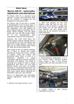
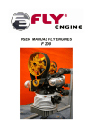
USER MANUAL C. Engine Release 1.0 – 15/11/09 CONTENTS 1. ENGINE IDENTIFICATION ................................................................... 3 1.1. Characteristics ................................................................................ 3 1.2. Seals ............................................................................................. 4 1.3. Engine performance ......................................................................... 5 2. ENGINE USE ........................................................................................ 6 2.1. Engine working parameters............................................................... 6 2.2. Alarms and safety mode ................................................................... 6 2.2.1. Engine alarms ........................................................................... 6 2.2.2. Safety mode ............................................................................. 6 2.3. Usual Maintenance........................................................................... 6 2.3.1. Engine warm up ........................................................................ 6 2.3.2. Lubrication................................................................................ 7 3. MAINTENANCE .................................................................................... 8 3.1. Oil tank.......................................................................................... 8 3.1.1. Removal ................................................................................... 8 3.1.2. Installation ............................................................................... 9 3.2. Engine ......................................................................................... 10 3.2.1. Removal ................................................................................. 10 3.2.2. Installation ............................................................................. 12 4. SENSORS ........................................................................................... 13 4.1. Water temperature sensor .............................................................. 13 4.2. Air temperature sensor................................................................... 13 4.3. Intake air pressure sensor .............................................................. 13 4.4. Engine speed and TDC sensor ......................................................... 14 4.5. Camshaft position sensor................................................................ 14 4.6. Camshaft shifter solenoid valve ....................................................... 14 4.7. Lambda sensor.............................................................................. 14 4.8. Engine Oil pressure sensor.............................................................. 15 4.9. Engine Oil Temperature sensor ........................................................ 15 4.10. Fuel pressure sensor .................................................................... 15 4.11. Motorized throttle ........................................................................ 16 5. CARBURATION MIXTURE ................................................................... 16 5.1. Fuel pump .................................................................................... 16 5.2. Fuel circuitry overview ................................................................... 17 5.3. Removal of the fuel circuit .............................................................. 18 5.4. Draining fuel tank .......................................................................... 20 5.5. Ignition plugs................................................................................ 21 C-2 Release 1.0 – 15/11/09 1. ENGINE IDENTIFICATION An engraving on the left of the engine unit identifies the engine. 1.1. Characteristics Type Number of cylinders Number of valves Engine displacement Bore Stroke Volumetric ratio Maximum power Maximum torque Maximum revs F4R 832 4 16 1998 cm3 82,7 mm 93 mm 15,1/1 210 bhp 220 Nm 7500 rpm C-3 Release 1.0 – 15/11/09 1.2. Seals The engine is sealed off. It is forbidden to carry out any intervention on the engine. An intervention can only be carried out by Renault Sport representatives. The seals of the engine must always be in a good condition. There are 5 seals on the engine and 1 electronic chip: Oil pump Camshaft plugs Oil pump pressure valve Dry sump Fuel ramp Tag on cylinder head Tag on dry sump C-4 Power (hp) C-5 40 60 80 100 120 140 160 180 200 220 3001 3250 3500 3750 Power Torque 4000 4250 4500 4750 5000 5250 5500 5750 6000 6250 6500 6750 7000 7250 150 170 190 210 230 250 270 290 Release 1.0 – 15/11/09 1.3. Engine performance Torque (N.m) Release 1.0 – 15/11/09 2. ENGINE USE 2.1. Engine working parameters Oil Temperature Water Temperature Oil Pressure Fuel Pressure Battery Voltage minimum at starting Battery Voltage minimum at idle speed Maximum engine speed 70°C – 130°C 60°C – 90°C 4.5 bars at 5000 rpm 3.5 bars ± 0.3 bar 11 V 12 V 7500 rpm 2.2. Alarms and safety mode 2.2.1. Engine alarms The alarms that might appear on the dash if the thresholds are exceeded are: Alarm Water temperature Fuel pressure Oil pressure Threshold >100°C <2 bars <2 bars 2.2.2. Safety mode To protect the engine from running too low in temperature, the following protection is enabled on the car: Water Temperature < 50°C < 40°C < 30°C RPM limiter 6500 rpm 5000rpm 4000 rpm 2.3. Usual Maintenance 2.3.1. Engine warm up - Press the “on” button to switch on the dashboard Keep the ignition switch on “off” position Press the starter several times for less than 30 s until the oil pressure displayed on the dash is higher than 1 bar Switch on the ignition (lower position) Start the engine Run the engine until the oil temperature reaches at least 50°C. C-6 Release 1.0 – 15/11/09 2.3.2. Lubrication The recommended level of engine oil is 3.5 L. First oil change 400 km Frequency of oil change 600 km Lubricant Elf Excelcium 5W40 Drain the oil from the cap situated on the right hand side of the car, on the rear face of the bell housing, underneath the oil temperature sensor. Change the oil filter every 600 km. To control the oil level, follow this process: - Warm up the engine - Hold the throttle pedal at more than 3000 rpm for 10 seconds - Switch off the engine - Check the oil level: it should be 83 mm under the top of the oil cover (upper face of the oil tank cover), which corresponds to 3.5 L in the oil tank. 83 mm Correspondence between the level in Litres and in mm Level from the top (mm) 65 83 97 113 140 170 202 Level (Litres) 4 3.5 3 2.5 2 1.5 1 C-7 Release 1.0 – 15/11/09 3. MAINTENANCE 3.1. Oil tank 3.1.1. Removal To remove the oil tank, the gearbox should be detached. To remove the gearbox, refer to the transmission manual (D). - Remove the left flat bottom - Drain the oil tank - Remove the oil decanter pipe (1) 1 - Remove frames. 7 the left (2) and right 3 4 Disconnect the oil entry (4) and exit (5) 2 Remove the floor stays on the left and right (7) 5 C-8 Release 1.0 – 15/11/09 - Disconnect the oil temperature sensor - Disconnect the engine rpm sensor (8) - Remove the clutch protecting plate (9) - Remove the 7 screws (10) and 1 bolt - Remove the oil tank. 3.1.2. Installation - Carry out the above steps in the reverse order. Observe torques. The tightening torque for the frames is 46 Nm. - Adjust the level of the engine oil. - Run the engine for 2 or 3 min, then check the oil level (§ 2.3.2.) C-9 9 8 10 Release 1.0 – 15/11/09 3.2. Engine 3.2.1. Removal It is possible to remove the engine without removing the oil tank. The gearbox has to be detached, to remove the gearbox refer to the transmission manual (D). - Remove the flat bottom - Remove left (1) and right (2) frames - Remove exhaust manifold (3) - Remove the left (5) and right (6) floor stays 3 2 6 7 - Uncouple the fuel quick coupler (7) 1 5 9 - Drain water - Disconnect the water circuit: disconnect the radiator entry (8) and the right engine water pipe (9). 8 C-10 Release 1.0 – 15/11/09 - Disconnect air temperature sensor - Remove air box - Remove butterfly rack, intake manifold, intake bend. 4 - Disconnect the sensors and looms in order to remove the engine loom completely: solenoid valve sensor (1), coils (2), intake air pressure sensor (3), water temperature sensor (4), lambda sensor the 4 injectors the alternator (7) the engine earths (8) 2 1 3 C-11 Release 1.0 – 15/11/09 8 7 - Put the engine down on a support - remove the swirl pot (9) - Untighten the 4 screws (10) of the lower engine support then the two screws from upper engine support (11) 9 11 - Uncouple the engine with its oil tank. 10 3.2.2. Installation Repeat the steps above in the reverse order. Tightening torque 46 Nm 46 Nm Engine nuts Frames C-12 Release 1.0 – 15/11/09 4. SENSORS 4.1. Water temperature sensor The water temperature sensor is installed on the water outlet unit. 4.2. Air temperature sensor The air temperature underneath the airbox. sensor is fitted 4.3. Intake air pressure sensor The intake air pressure sensor is fitted in front of the intake manifold. C-13 Release 1.0 – 15/11/09 4.4. Engine speed and TDC sensor The engine speed sensor is fitted on the right hand side of the bell housing, above the starter motor. 4.5. Camshaft position sensor The Camshaft position sensor is fitted behind the intake manifold, next to the fuel ramp end. 4.6. Camshaft shifter solenoid valve The camshaft shifter solenoid valve is fitted on the cylinder head in front of the plugs. 4.7. Lambda sensor The lambda sensor is fitted on the catalytic converter. C-14 Release 1.0 – 15/11/09 4.8. Engine Oil pressure sensor The engine oil sensor is fitted on the rear of the intake manifold. 4.9. Engine Oil Temperature sensor The engine oil temperature sensor is fitted on the back of the oil tank, left hand side. 4.10. Fuel pressure sensor It is located near the pressure regulator on the top of the fuel tank. C-15 Release 1.0 – 15/11/09 4.11. Motorized throttle The motorized throttle is located between the air filter and the intake manifold. For diagnostic purpose, power is supplied to the motorized throttle for 30 seconds when the dash is switched on. 5. CARBURATION MIXTURE 5.1. Fuel pump Fuel pump reference: Nominal flow rate: AOU 195. 102 l/h. 3 The fuel pump assembly contains: Electric pump (3) Filter mounting (2) Fuel filter (1) 2 1 The pump is driven by the computer upon ignition switch and while the engine is running. When the car is switched on, the pump runs for 3 seconds. Fuel filtre exchange: - Separate the filter/mounting assembly from the pump Remove screw and washer Remove filter from its mounting On installation, make sure that the seals and gaskets are correctly positioned on the filter. Tighten the screw using Loctite 222. C-16 Release 1.0 – 15/11/09 5.2. Fuel circuitry overview C-17 Release 1.0 – 15/11/09 5.3. Removal of the fuel circuit - dismantle superior and inferior airbox - disconnect the fuel pressure sensor and disconnect the fuel pipe - loosen the four screws from the fuel catch tank support - unscrew the 15 screws left on the tank cover - extract the fuel pump assembly circuit without the fuel catch tank - remove the fuel catch tank C-18 Release 1.0 – 15/11/09 Note: During the assembly and disassembly of the fuel tank, to avoid that the metallic plate peels off from the fuel tank, use at least 4 screws to tighten the plate against the fuel tank. The screws should be used at least at each corner as shown below. (These screws are used only during assembly and disassembly of the fuel tank). C-19 Release 1.0 – 15/11/09 5.4. Draining fuel tank Disconnect the quick coupling device next to the intake manifold. Plug a hose in the female connector Connect a switch to the connector situated next to the top of the fuel tank to activate the pumps manually (refer to Chapter 6.6 of the electronics manual). The dashboard must be switched on. C-20 Release 1.0 – 15/11/09 5.5. Ignition plugs Removal - remove the airbox - remove the motorized throttle (loosen the screws) - disconnect and remove ignition plugs Installation Proceed in the reverse order of removal. Tightening torque 24 Nm Spark plugs C-21