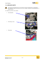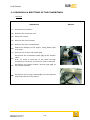
1
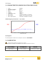
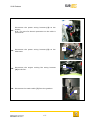
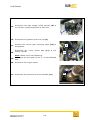
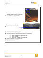
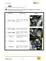
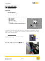
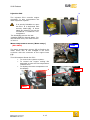
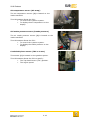
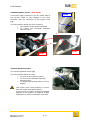
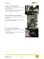
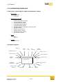
USER MANUAL C. Engine 2010 Release 2 ENGINE CONTENTS 2 ENGINE 2 2.1 ENGINE 2.1.1 ENGINE IDENTIFICATION 2.1.2 CHARACTERISTICS (ENGINE EVOLUTION F4R832 2010) 2.1.3 LUBRICATION 2.1.4 SEALED PARTS 2.1.5 REMOVAL & REFITTING OF THE POWERTRAIN 2.2 FUEL MIXTURE 2.2.1 PRESENTATION 2.2.2 OPERATING PRINCIPLE 2.3 STATIC IGNITION 2.3.1 DESCRIPTION 2.4 POWER SUPPLY 2.4.1 DESCRIPTION 2.5 2009 RELIABILITY 2.5.1 5V ACCESSORY BELT : 77 11 162 521 2.5.2 ENGINE STARTER & HEAT SHIELD 2.5.3 ENGINE STARTER LOOM 2.5.4 TIMING BELT PROTECTIVE SCREEN 2.6 TIGHTENING TORQUES C-2 3 3 4 4 5 6 13 13 20 22 22 23 23 23 23 24 25 26 27 2010 Release 2.1 ENGINE 2.1.1 ENGINE IDENTIFICATION The engine is identified by an engraving located on the engine block. It includes: In A: the engine type and homologation letter. In B: the engine index. In C: the engine manufacturing number. B A C There is a reminder of the engine manufacturing number on the camshaft blanking cover plate. If the number indicated on the camshaft blanking cover plate does not correspond with the one engraved on the engine, the latter is correct. Any procedure carried out on the engine not included in this manual must be performed by a Renault Sport accredited engine partner. C-3 2010 Release 2.1.2 CHARACTERISTICS (ENGINE EVOLUTION F4R832 2010) Type: Number of cylinders: Number of valves: Bore: Travel: Capacity: Compression ratio: Max. power: Max. torque: Max. engine speed: F4R 832 4 inline 16 82.7mm 93mm 1998 cm3 11.5/1 152,3kW (207bhp) at 7,300rpm 223Nm (22.7m.kg) at 5,550 rpm 7,500rpm (5,000rpm in neutral) F4R 832 engine performances – Cup version Power [bhp] 210 80 190 70 170 60 150 50 130 40 110 30 90 20 70 10 50 2000 3000 4000 5000 6000 Torque [mkg] 0 8000 7000 Engine speed [rpm] Homologation The homologation number for the catalytic converter is ROSI 50181. 2.1.3 LUBRICATION The minimum quantity of engine oil is 4 litres. To prevent any oil surge, it is essential to drive with a minimum of 4 litres. First oil change Oil change rate Lubricant After 500km Every 1,000km Elf Exelcium 5W40 C-4 2010 Release 2.1.4 SEALED PARTS The engine has sealed parts. The presence of these sealed parts is mandatory. No procedure may be carried out on the engine unless by representatives of Renault Sport. The following sections are sealed: The camshaft The timing cover The sump C-5 2010 Release 2.1.5 REMOVAL & REFITTING OF THE POWERTRAIN Removal Operations Photos 1 - Disconnect the battery 2 - Remove the drivetrain nuts. 3 - Raise the vehicle. 4 - Remove the front bumper. 5 - Remove the front crossmember. 6- Attach the radiator to the engine, using plastic clips or a strap. 7 - Remove the air box and intake pipe. 1 Disconnect the accelerator cable (1) at the throttle valve. 8N.B.: To avoid a wear-out of the cable through scrubbing on the body, the use of a collar is allowed. 9- Disconnect the brake booster vacuum pipe (2) at the intake manifold. 10 - Disconnect the wiring harness (3) at the bulkhead and bring it back to the engine. 2 3 C-6 2010 Release 4 Disconnect the power wiring harness (4) at the starter. 11 N.B.: The use of a thermic protection on the cable is preconized. 5 Disconnect the power wiring harness (5) at the 12 alternator. 13 - Disconnect the engine cooling fan wiring harness (6) at the fan. 6 14 - Disconnect the earth cable (7) from the gearbox. 7 C-7 2010 Release 15 - Disconnect the high voltage wiring harness (8) at the coil box, noting the position of each wire. 8 16 - Disconnect the gearbox control tie-rod (9). 17 - 18 - Unscrew the reverse gear unlocking cable (10) at the gearbox. Disconnect the clutch control pipe (11) at the master cylinder. 9 10 11 Note: Watch out for fluid discharge. 19 - Disconnect the fuel pipes, at the ”T” on the bulkhead side. 20 - Disconnect the oxygen sensor. 21 - Disconnect the exhaust line at the manifold (12). C-8 12 2010 Release Cut the 2 plastic collars fixed to the left and right subframe tubular trusses (réf. 22 77 11 160 147 et 77 11 160 146). 23 - Unscrew these 3 screws (13). (13) 24 - Remove the inferior protection plate 25 - Remove the subframe (see 4-2 Front axle/Removing the subframe). Remove the drivetrain: Extract the drivetrain on the gearbox side. 26 Tilt the drivetrain. Extract the drivetrain on the wheel side. 27 - Place the powertrain on a hydraulic plate. 28 - Remove the lower crossmember. 29 – Remove the front end. C-9 2010 Release GB mountings Engine mountings 27 - Separate the engine mounting when removing the shaft (1). 28 - Separate the gearbox mounting (2): Release the shaft Remove the three mounting bolts 29 - Take out the powertrain and lower the hydraulic plate. C-10 1 2 2010 Release Refitting Carry out the previous operations in reverse order. When refitting the powertrain, it is important to comply with the following positioning procedure for the powertrain in order to guarantee the operational clearances required for the drivetrain. Operations Components Photos 2 1- Assembly + torque tightening: 75 Nm. Gearbox buffer mounting (1) on the left side member. 2- Assembly + torque tightening: 62Nm. Connecting torque rod yoke (5) on the gearbox spacer. 1 5 3- Assembly + torque tightening: 75Nm. Gearbox mounting (2) on gearbox buffer mounting (1). 4- Assembly + prescrewing. Connecting torque rod on subframe (rubber buffer on subframe side) 6 5- Assembly + prescrewing. Engine suspension (3) on the right side member. 6- Assembly + prescrewing. Engine mounting cover (4) on the engine suspension (3). C-11 3 4 2010 Release 7 - Fitting of engine in the engine compartment, from below. 8 - Torque tightening: 75Nm. Gearbox mounting (2) on the gearbox. 9 - Torque tightening: 105Nm. Connecting torque rod on yoke (5). 10 - Torque tightening: 62Nm. Engine mounting cover (4) on the engine mounting (6). 11 - Torque tightening: 62Nm. Engine suspension (3) on the right side member. 12 - Torque tightening: 105Nm. Gearbox mounting (2) on the gearbox buffer mounting. 13 - Torque tightening: 105Nm. Connecting torque rod on the subframe. 14 - Torque tightening: 105Nm. Engine mounting cover (4) on the engine suspension. C-12 2010 Release 2.2 FUEL MIXTURE 2.2.1 PRESENTATION Fuel circuit Fuel pump assembly Flow: 80lph. Pressure: 3.5 bar The fuel pump assembly is immersed in the fuel tank. (1) Fuel outlet (2) Connector (3) Electric pump (5) Pressure regulator (6) Dipstick (4) Fuel filter located in the body of the assembly. This filter cannot be replaced. The pump is controlled by the ECU as soon as the ignition is switched on and the engine is running. If, 3 seconds after the ignition has been switched on, the engine does not start, the pump stops. Draining the fuel tank The switch (3) on the control panel is used to activate the fuel pump. The hose (part no. 77 11 160 444) is connected to the quick-fit coupling (1) to drain the fuel tank C-13 3 2010 Release Note: You are advised to stop the tank draining right from the first signs of any “air bubbles in fuel” at the draining pipe end. Therefore the tank draining is not complete and a few fuel quantity stay in the tank (variable from a car to an other) because it cannot be drained by this method. In order to prevent annoyances from a technical non-conformity following a fuel check, you are advised to apply the tank draining procedure and to use the official fuel right from the free sessions before the current event. C-14 2010 Release 2 Injection ECU The injection ECU controls engine operation. It also incorporates the data acquisition system. It is strictly forbidden to open the ECU. It is delivered with security labels (1). If these labels are missing, this can be considered a technical noncompliance. The decal (2) precise the last upgrade made by Renault Sport. For the F4R 832 2010, the decal version is 2010.1 1 1 Water temperature sensor (Water temp.) (EVO 2010) The water temperature sensor (1) is fitted to the water outlet unit. It has changed in the 2010 evolution with the connector of the engine loom (2) 2009 1 This information allows the ECU: To control the injection system. To control the engine cooling fan assembly as soon as the temperature reaches 95°C. To display the water temperature on the display 2 2010 1 2010 C-15 2010 Release Air temperature sensor (Air temp.) The air temperature sensor (1) is located on the intake manifold. 1 This information allows the ECU: To control the injection system. To display the air temperature on the display. Air intake pressure sensor (Intake pressure) The air intake pressure sensor (1) is located on the intake manifold. This information allows the ECU: To control the injection system. To display the intake pressure on the display. 1 Crankshaft phase sensor (TDC or S mot) This sensor (1) is located on the gearbox spacer. This information allows the ECU to specify: The Top Dead Centre (TDC) position. The engine speed. C-16 1 2010 Release Camshaft phase sensor (EVO 2010) 2009 This sensor (1) is located on the air intake side of the cylinder head. It has changed in the 2010 Evolution with the connector of the engine loom (2) 1 This information allows the ECU to specify: The position of the intake camshaft. To control the camshaft dephaser solenoid valve. 1 2 2010 2010 Throttle position sensor The throttle position sensor (1) This information allows the ECU: To control the injection system. To control the camshaft dephaser solenoid valve. To display the throttle position on the display. This sensor must work properly to ensure that the engine operates properly. In the event of a fault, an alarm message appears on the display. An analysis of data acquisition is used to anticipate any faults. C-17 1 2010 Release Oxygen sensor (Lambda sensor) The oxygen sensor (1) is located on the exhaust manifold. 1 This information allows the ECU to control the injection system. Camshaft dephaser solenoid valve (EVO 2010) This actuator (1) allows, under the ECU Control, the variable timing of the intake camshaft It has changed in the 2010 evolution with the connector of the engine loom (2) 2 1 C-18 2010 Release Engine cut-off switch (Upshift) 1 This switch (1) is located at the end of the gearbox control bar. This information allows the ECU to control the engine cut-off during the gear upshift. Barrel position sensor (Potentiometer) This sensor (1) is located at the end of the gearbox barrel. This information allows the ECU to display the gear selected on the display. 1 Oil pressure sensor (Oil pressure) This sensor (1) is located on the engine pressure rail. This information allows the ECU to display the oil pressure on the display. C-19 1 2010 Release 2.2.2 OPERATING PRINCIPLE Components comprising the engine management system Fuel circuit Fuel pump Injectors Management system Injection ECU Water temperature sensor Air temperature sensor Intake pressure sensor Crankshaft phase sensor Camshaft phase sensor INTAKE camshaft dephaser solenoid valve Oxygen sensor Engine cut-off switch Barrel position sensor Throttle position sensor Oil pressure sensor Power Coil Starter Cooling Motor fan Schematic diagram Battery V Water temp Air temp Oil pressure Intake pressure Crankshaft phase Oxygen sensor Barrel position Throttle position Camshaft phase Upshift cut-off Injection ECU Dephaser solenoid valve Oxygen probe heating Injectors Coils Fuel pump Motor fan C-20 Starter 2010 Release Starting Starting from cold is made easier if the electrics are switched on by the circuit breaker (button (1) on the control panel). In this case, the ECU performs a "cold start". It controls the fuel pump then, after the engine start command, performs wall wetting injections. Also, if cold starting fails, it is advisable to turn off the general power supply and repeat the engine start procedure. Deceleration cut-off When the throttle is fully closed and the engine speed is greater than 3,000rpm, the injectors are no longer controlled. Injection is reestablished in one of the following two cases: - Throttle opening: 10%, - Engine revs are less than 3,000rpm Battery voltage The ECU requires a voltage with the starter activated greater than 8 volts. Below this threshold, the battery must be charged or replaced. In order to avoid damage to the ECU, it is not advisable to use a battery ”booster”. Operation in downgraded mode The ECU performs a self-diagnostic from input parameters and warns the driver of an abnormal measurement by means of an alarm on the instrument panel. The alarm is activated on the instrument panel as soon as the fault is present. Each alarm is registered in the form of a diagnostic code in the data acquisitions. In the event of an abnormal parameter, the ECU works in downgraded mode with a default value for the faulty input. These values are: Air temperature: 20°C. Water temperature: 98°C. Throttle potentiometer: 98%. Intake pressure: reconstituted from a map indexed on speed/throttle. C-21 2010 Release 2.3 STATIC IGNITION 2.3.1 DESCRIPTION General The system includes: The ECU which incorporates the ignition power stage. A module comprised of two twinoutlet coils. Four spark plugs. A high voltage wiring harness. Injection ECU The injection ECU controls engine operation. It also incorporates the data acquisition system. Coils (1) The coil box is fitted above the front right wheel arch. It is made up of 2 ignition coils. Each coil is controlled separately by the ECU and causes two sparks simultaneously: The coil for cylinders 1 and 4 is controlled via tracks 56, 62 and 63 of the ECU (CH2). The coil for cylinders 2 and 3 is controlled via tracks 33, 41 and 42 of the ECU (CH2). Spark plugs For correct engine operation, it is essential to use spark plugs with part no. 82 00 492 426 C-22 2010 Release 2.4 POWER SUPPLY 2.4.1 DESCRIPTION 1 The injection circuit is comprised of an aluminium rail (1) and four injectors (2). The fuel circuit is without backflow. It is made up of reinforced flexible pipes and screwed unions (3). 3 2 2.5 2009 RELIABILITY 2.5.1 5V ACCESSORY BELT : 77 11 162 521 This new belt has the same length as the old one, but only 5V. It solves the problem of premature wear encountered on a few cars. Please respect the following mounting indications: Position on motor pulley : Let free the internal groove of the pulley (engine side). Free grooves Position on alternator pulley : Fit the belt in the middle of the pulley, letting free both external grooves. C-23 2010 Release Position on free pulley : Fit the belt in the middle of the pulley, letting free both external grooves. Free grooves The 6V belt 77 11 162 383 is no longer available. 2.5.2 ENGINE STARTER & HEAT SHIELD A new starter motor (ref. 77 11 162 617) and a new starter motor heat shield (ref. 77 11 162 618) are now available at your Renault Sport Spare Parts Department. These parts can be fitted directly on the car without any modification. Nevertheless, the heat shield ref. 77 11 162 618 is especially designed for the starter motor ref. 77 11 162 617, which is smaller. As a consequence, only this new heat shield can be fitted on the new starter motor. The heat shield is now tightened directly on the engine with a M10 screw (ref. 77 03 002 912). Tightened on the engine block C-24 2010 Release 2.5.3 ENGINE STARTER LOOM Otherwise, Renault Sport recommends you to mount your starter motor loom as shown on the pictures below: Mount the plastic bracket on the lowest thread stud (1) Put one cable through each plastic buckle (2) Connect the loom to the starter motor from the engine block side (3) o It could be needed to bend the cable terminal in order to prevent from touching the solenoid excitation (4) Pass the loom through a metal support fitted on the engine block (5) Exhaust heat shield (2 ) (1) Thread stud Bottom view, behind the exhaust heat shield Solénoïd (4) (5 (3 NOTE : Old parts are no onger available. C-25 2010 Release 2.5.4 TIMING BELT PROTECTIVE SCREEN To strongly improve the timing belt protection. The timing belt protective screen has been replaced by the new screen below, under the new reference 77 11 162 626. These protective screens will be mounted on the 2010 F4R832 Clio Cup engines. Only the new protective screen 77 11 162 626 will be allowed in 2010. The old one 77 11 162 255 is no longer available. Assembly recommandation : Fit some sealing paste on the timing pinion cover before mounting the protective screen, as shown on the picture below: C-26 2010 Release 2.6 TIGHTENING TORQUES Tightening torques in Nm Components Gearbox buffer mounting on left side member 75 Connecting torque rod yoke on gearbox spacer 75 Gearbox mounting on gearbox 75 Connecting torque rod on the yoke 105 Engine mounting cover on the engine mounting 62 Engine suspension on the side member 62 Gearbox mounting on the gearbox buffer mounting 105 Connecting torque rod on the subframe 105 Engine mounting cover on the engine suspension 105 C-27