1
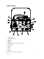
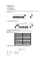
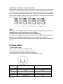
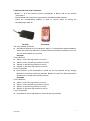
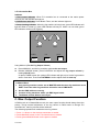
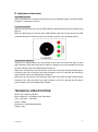
User Manual VPF-1500 Table of contents Introduction ................................................................................................ 2 Safety Information ..................................................................................... 2 Panel Review ............................................................................................. 3 Operation ................................................................................................... 4 DMX Mode .......................................................................................... 4 Master Mode ....................................................................................... 5 Max. Output Function……………………………………………………...7 Indicators Instruction……………………………………………………….8 Techinical Specification .............................................................................. 8 1 PY-S242071 INTRODUCTION Thanks for purchasing VPF-1500 Please read this manual carefully and thoroughly, as it gives important information regarding safety and operation instruction. Keep this manual in order to consult it in the future. The quality of every set of the products is guaranteed in the factory before the shipment. Please check the accessories as the packing list inside. If the carton appears to be damaged, please inspect the fixture carefully. In case damage has been found or some parts are missing, please contact the after service department before shipping back the product. Packing list ·Power cord ·User manual ·Maintenance card ·Wireless receiver ·Wireless transmitter ·Controller box ·VPF-1500 fog machine ·Tank SAFETY INFORMATION ·Always make sure that you are connecting to the proper voltage, (see parameters chart) and the voltage can be allowed to fluctuate±10%. ·Ground the power cord. ·Use the professional fog juice, otherwise it will affect fog machine’s performance and shorten its lifespan. (DO NOT USE OIL) ·Put the fog machine in a well-ventilated place. ·For indoor use only and do not use it in a humid and drenched place. ·Do not heat fog juice and always keep it in normal ambient temperature. ·Do not dilute juice with water or other liquids. ·Inedible fog juice! No drinking! ·Do not put your hands close to aperture of the fog machine ·Keep the machine out of the children’s reach. ·Far away from flammable and explosive materials in case of hurt. ·Put the fog machine on the ground or solid work areas instead of hanging on the shelf. ·Keep at least 60 centimeters distance from people when fraying ·Non-professionals should not dismantle fog machine in case of electrical shock or scald. ·Do not change inner components and fixtures. 2 PY-S242071 PANEL REVIEW 1. Manual switch 2. Temperature indicator 3. Dipswitches 4. DMX in 5. DMX out 6. Controller box output or wireless receiver output 7. Switch on/off 8. Power socket 9. Interval 10. Timer 11. Control 12. Manual 13. Value Notes: 9~13 buttons are on the controller box. 3 PY-S242071 OPERATION A. DMX Mode 1. Setting DMX mode When Switch10 is ON, the system enters into DMX mode and DMX address can be set through Switch 1~9. 2. Calculating DMX address Addr=Add1+Add2+Add3+…Add9 For example: If switch #2 and switch#3 is on and the left are off as above, DMX address Value =2+4= 6. Switches Binary value Switch 1 Off 0 Switch 2 On 2 Switch 3 On 4 Switch 4 Off 0 Switch 5 Off 0 Switch 6 Off 0 Switch 7 Off 0 Switch 8 Off 0 Switch 9 Off 0 3. Multi-fog machines connection -Three-pin instruction PIN1 PIN2 PIN3 GND - COLD + HOT ground negative pole positive pole 4 PY-S242071 4. Multi-fog machines connection method DMX fixtures are designed to receive data through a serial Daisy Chain. A Daisy Chain connection is where the DATA OUT of one fixture connects to the DATA IN of the next fixture. The order in which the fixtures are connected is not important and has no effect on how a controller communicates to each fixture. Use an order that provides for the easiest and most direct cabling. Connect fixtures using shielded two conductor twisted pair cable with three pin XLR male to female connectors. Notes: When it is not controlled by the controller, only one fog machine can be set as MASTER with the other fog machines set as SLAVES. All of blue LED indicators of Slaves will be on/ off regularly. Connect the controller with the fog machines with 3-pin DMX signal cable and the DMX address of SLAVES ranging from 001~511 should be set uniformly. The fog machine is distributed with one channel and channel value decides fog machine’s output. B. Master Mode 1. Setting Master mode When the 10th switch is off, it is Master mode. In Master mode, fog machine is controlled either by a Z-6 controller box or a wireless receiver and transmitter 5-Pin Connector for the z-6 controller box or Wireless receiver 2 ways z-6 Controller Box Wireless Receiver Pin1 Vcc Vcc Pin2 Gnd Gnd Pin3 Smoke max output Smoke max output Pin4 Smoke dim output Antenna Pin5 Green-LED Null Pin 5 PY-S242071 2. Wireless Receiver and Transmitter —Button 1 ~ 4 on the wireless receiver corresponds to Button 1~4 on the wireless transmitter’s. —The transmitter can control four fog machines with different DMX address. — Select the corresponding address in order to receive signal by setting the corresponding switch On. Receiver Transmitter The using method as follows: Set different address for 4 fog machines. Switch 1~4 correspond to different address. Switch On means the address is set while Switch Off means the address is not set. You can set the Switch as you need. Example1 For the Receiver Switch 1 on the first fog machine is set On. Switch 2 on the second fog machine is set On. Switch3 on the third fog machine is set On. Switch4 on the fourth fog machine is set On. For the Transmitter Press Button1 on the transmitter to control the first fog machine and by analogy Button2 to control the second fog machine, Button3 to control the third fog machine and Button4 to control the fourth fog machine. Example2 For the Receiver Switch 1 on the first fog machine is set On. Switch 1 on the second fog machine is set On. Switch1 on the third fog machine is set On. Switch1 on the fourth fog machine is set On. For the Transmitter Press Button1 on the transmitter to control all the fog machines. 6 PY-S242071 3. Z-6 Controller Box Indicator 1. Red control indicator: When Z-6 controller box is connected to the mains power correctly, the red indicator will light on. 2. Yellow timer indicator: Press Button Timer, and the indicator lights on. 3. Green heating indicator: When the fog machine is being heat, green LED indicator will light off; When it is heat up, green LED indicator will stay on. When it is over heat, green LED indicator will be on/off regularly. Interval Yellow timer value red control green manual Using Method: (For the Fog Output Volume) Press MANUAL, and the fog machine reaches the max output. Release MANUAL button, press CONTROL and adjust the fog output volume by rotating VALUE knob. Or press TIMER button (the yellow LED indicator will light on) to let the fog machine work in fixed time. Then rotate INTERVAL knob to adjust fixed the time-up. Notes: In Master/Slave 1. Only one fog machine can be set as MASTER with the other fog machines set as DMX. That is the other fog machines should be set to DMX Mode. 2. Set the DMX address correctly. 3. Connect all fog machines with 3- pin DMX signal cable. 4. The Master and the Slaves run in-sync. C. Max. Output Function In DMX mode or in Master/Slave mode, the max output function should always have the priority. Trough manual adjustment of the fog volume in DMX mode or through Z-6 controller box, max fog volume will be achieved. The following operation will enable the max fog volume. 1. Press 1~4 button on the wireless transmitter to enable. 2. Press MANUAL button on the Z-6 controller box to enable. 3. Press green MANUAL button on the panel to enable 7 PY-S242071 D. Indicators Instruction Blue DMX Indicator: When fog machine is in Slave mode and receives the valid DMX signal, the LED indicator will light on, otherwise it turns off. Fog Juice Indicator: When the tank has no juice, two red LED indicators will flash and two green indicators will light off. When the tank has juice, the two green LED indicators will stay on and the two red LED indicators will light off. (See the fog juice indicators’ position in the following picture) Temperature Indicators: When juice is being heated, the red indicator at the side of the tank will light on while green indicator at the side of the tank, the green indicator on the Z-6 controller box as well as green indicator above the dipswitches will light off. When juice is heated-up, the red indicator at the side of the tank will light off while green indicator at the side of the tank, the green indicator on the Z-6 controller box as well as green indicator above the dipswitches will light on. When juice is over-heat, the red indicator at the side of the tank will light off while green indicator at the side of the tank, the green indicator on the Z-6 controller box as well as green indicator above the dipswitches will flash. TECHNICAL SPECIFICATION Model: VPF-1500 fog machine Input voltage: AC 110V/60Hz or AC 230V/50Hz Fuse: 15A /125V , 10A /250V Power: 1500W Dimension: L530XW239XH215mm Weight: 15kg 8 PY-S242071