1
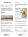
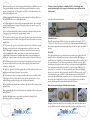
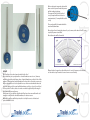
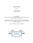
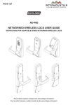
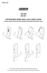
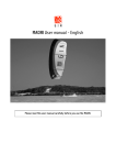
CB La Gard 2200
with Variable VMI Indicator
COMPLETE USER MANUAL
By Chris Belcher
CB LA GARD 2200
Product Code: CB-LG2200VMI
12.50 inches
These tools have been manufactured in the South West of England, and are made of
Stainless steel with Aluminium Thumb-turns.
HORIZONTAL LINE [LINES 1+2
SLOTTED NOSE
PICK STEM
RADIAL POSITION LINES
THUMBTURN
The Tool
1. The Pick enables the Locksmith to replicate the key by manipulating each of the
wheels individually, to align each wheels gate under the fence. It is also used to
position the driver wheel under the fence.
2. The Pick has a slot cut into the Nose end, to allow the Pick to engage the drive tooth
in the key-way of each wheel (one at a time).
3. At the Thumb-turn end, there are 4 Radial Position Lines (rings) machined, these lines
are useful when practising on a lock to indicate the linear position of the Pick within
the lock (a magnetic based pointer can be used in conjunction with the Radial Position
Lines, and when proficient in the Pick’s use, is probably not required).
4. There are two Horizontal Lines machined along the length of the Pick.
5. The first Horizontal Line is in line with the centre of the Nose end slot, and is used to
indicate the radial position of the Pick, and can also be used as a reference to mark on
the safe door the parked position of each wheel.
CB LAGARD
CB LAGARD
The CB LaGard 2200
Introduction:
The reason why I decided to manufacture my version of a tool to manipulate the La
Gard 2200 was because I had a spate of jobs where it was my job to Open / Effect Entry
to this lock where the key guide Tooth within entrance to the key way had broken
off. I was so frustrated one day, and being unaware that any other tools existed for
manipulating this lock, I quickly made a prototype to overcome the problem, this set
me on the road to thinking that it would be a useful tool for other Safe Technicians,
therefore, in a nutshell, this is a most basic tool to manipulate the La Gard 2200 –
precision made and economical, using the same design that La Gard uses for the Tip/
Nose end of the tool. This enables the user to manipulate through the pack and make
easy work of a job that could have been more problematic with the key guide Tooth
missing.
6. The second Horizontal Line is machined 150 degrees (anti-clockwise) from the centre
of the slot in the Nose of the pick.
7. This Horizontal Line is used to set the driver wheel under the fence of the drop arm
and is also useful for indicating the maximum amount of wheel movement allowed in
this procedure.
The Lock
1. The lock is a changeable key lock and is similar to a 4 wheel combination lock in
that it has 4 wheels plus one driver wheel
(with the same diameter). Each of the four
wheels has one true gate and 11 false gates
around its circumference; the wheels TRUE GATE
are held in place within a cylinder
DRIVE TOOTH
by plastic spacers which, are in turn,
secured with a plate and circlip. (The FALSE GATE
spaces thus formed between the
wheels make it easy to know when you have
disengaged one wheel and engaged the next)
also it has a drop arm and fence similar to a
standard combination lock which is constantly
at rest on the wheel pack.
2. A key is used to turn all the wheels at the same time to position the true gates under
the fence and open the lock.
Manipulation
Note:-To begin with, the best method is to use a sound amplifier, although with
experience it can be done by feel alone.
3. Firstly, check the handing of the lock. This is normally fairly simple as a key-hole
escutcheon with an index line is normally fitted. (With the index line at 9 o’clock the
lock is down shoot), if there is not an index line then insert the pick into the key-way
and rotate it until it engages the key guide tooth within the key-way at the entrance to
the lock, (you can check that you are correct because you will not be able to turn the
pick in either direction) then using the picks front end slot centre line as a reference
make a mark on the safe door to act as the index line.
4. Next insert the pick into the lock as far as it will go. The pick is now engaged with the
driver wheel.
5. Rotate the pick 150 degrees clockwise as indicated by the line on the pick being inline with the index mark on the safe door. This has now aligned the driver wheel under
the drop arm fence.
7. When engaged with the first wheel, set up the pointer in line with the radial lines on
the pick (it will be the one nearest the thumb-turn)
8. To start picking move to each wheel in turn starting with number 1 wheel and with
only very small movements rotating left and right, position each wheel in a gate. (This
may be a true or false gate).
9. This is easily determined by the clicking sound made by the fence striking the sides
of the gates, next, return the pick to engage number 1 wheel
10. The next part of the procedure can be anywhere between two extremes which are
dependent upon the level of the locks background noise and the resistance to rotation
of each wheel.
11. The easiest lock to open that I have found, is where the noise of the fence scraping
the wheels can be heard over the locks background noise. In this case rotate each
wheel in turn until the scraping noise of the fence ceases (I have found that in most
cases that starting with number 1 wheel then 2 etc., works well because there is a
certain amount of movement of the wheels within their housing, and with the pick
holding the 1st wheel in position, the other wheels move fractionally out of the way).
12. You may now have to go back to each wheel and nudge them each in turn, to get
the drop arm to fall, once it has, move the pick to engage the drive wheel and turn
clockwise to open the lock.
13. If you try to open the lock whilst engaged with any of the combination wheels, you
might cause some damage if the wheel starts to ratchet.
14. In the worst case, there is no scraping sound from the fence on the wheels, in this
case you have to listen or feel for the clicks as the gates move past the fence. As you
approach the true gate the clicking sound to that wheel will diminish.
15. At this point stop moving this wheel and move onto the next wheel and repeat the
same procedure.
16. Keep repeating this with each wheel in turn, and eventually you’ll have all the gates
under the fence.
Final Note: Only with practise can you develop a system for picking this lock.
The above procedures are extremely variable.
CB LAGARD
CB LAGARD
6.Release any tension on the pick and gently pull it backwards, you will feel it come out
of engagement with the driver wheel and butt up against the first wheel, rotate the
pick anti clockwise back to the start position, and feel for the first wheels drive tooth,
whilst gently pulling backwards.
“We were contacted by a Master Locksmith of the B.L.I., Alan Morgan, who
wanted, after buying the tool, to appraise it and write a review, below is his unedited review.”
La Gard 2200 Pick from Chris Belcher.
LaGard 2200 Lock The pick is on sale through Duffells in London and available in three lengths 5.25”,
7.25” and 12.5”. The pick is one piece of stainless steel with an aluminium thumb wheel,
there are two engraved lines along the length of the pick and four rings to give wheel
spacing.
Chris’s Pick This solid construction gives a positive feel for every vibration, the scraping of a wheel
against the fence is discernible by touch even in a busy bank lobby. When using an
amplifier there is no distracting noise from pick parts moving against one another, just
the sound of the fence. The two lines are great time savers for two reasons; the first
index line runs along where the drive cut out is, you can insert the pick easily and then
know exactly where each wheel is at any time. You can also realign all the wheels to
insert a key. The second line at 120º lets you quickly line up the drive cam under the
drop in so you can feel the fence against each wheel. BUT ALSO shows you the range
of positions that the gate could be in. To clarify, the wheels spin 360º without limit,
however the gate will fall within a segment of only 120º as the key would be weakened
by very long cuts needed for more rotation. In a lost key situation you can normally
assume that the gate will be situated within the first third of a turn.
Drive cam in position with gate of 4th wheel just showing -
Navigation between the wheels is as easy as picking a Union three lever with a two in
one, you don‟t even need to remember which wheel you‟re turning if you can feel it
Spacers, Wheel and Drive Cam So, you can position the drive cam and get great feel of the fence touching the wheels
as you turn them, you can easily navigate between any part of the lock or even remove
the pick with the lock open. You know that the gate will be in the first third of a turn
and you can position the wheel exactly where you want. Sounds like your Mum could
pick these now doesn’t it? She could and so could Mike’s dog. Though I was talking to
one very accomplished lock picker recently who has not got on with this tool, but this
may be because he is so used to the Phil Shearer pick.
Top Spacer & Wheel My pick arrived in a plastic storage tube with a sheet of hints and instructions, naturally
I ignored the paperwork and grabbed a lock straight away. on my desk in a quiet office
I had the lock open in far less than fifteen minutes. Reading through the helpful hints
then gave me the benefit of Chris’s experience and, using the techniques described,
halved the time it took to open my next practice lock. I had a couple of brand new locks
to hand and one with damaged drive tabs, the pick breezed through every time on any
key differ I set up. That’s the main point I will stress, in the last few months I’ve opened
a good number of these locks on an assortment of safes and they’ve all been fairly
easy. As yet the only time I’ve used an amplifier was whilst practising. So far my best
time was under three minutes on a lock, on a bridge mount, on the plate door of an
ATM. That was shortly after buying the pick when I was still timing myself (like the sad
obsessed man I am).
Tip of Pick A common problem with the 2200 is when the small tangs between cuts on the key
bend or break. This had happened on a Leigh UFS last year and I struggled to remove
the broken bit from the bottom of the lock. However the customer’s key would still go
in and turn, I could hear the fence drop and pull the bolt back. I believed the problem
was the relock rather than the key and was about to drill rather than keep fishing for
the broken tang. Partly for my own amusement I took the time to pick the lock and
was surprised when the safe lid then turned. Somehow the broken piece must have
prevented the key from turning fully as the same key worked well after I cleaned the
lock out. No one was happier than the customer, I’d told him that it would be cheaper if
I didn’t have to drill!
One point I will add about picking this lock. The bottom of the fence is rounded not
square, so whilst you can feel the edges of the gate it’s not with the edges of the fence.
You need to make sure you position the wheel right between the contacts to save
going back and nudging to finish the job. See photo.
CB LAGARD
CB LAGARD
scraping. So far all the locks I’ve worked on have still had good tension so the wheels
stay in position and don’t get caught as you manoeuvre away. I imagine if the clip had
failed or the wheels were very loose it would require a delicate touch to line them all up
but this tool should still do the job.
Notice the Radius of the Fence If you don’t own one of Chris’ La Gard picks you should now be thinking one of two
things, „I’ll buy one or ‘Why did I spend so much on that pick from America?!’
Alan Morgan. M.B.L.I.
March 2005.
[Extra] Operating & Changing Instructions for the La Gard 2200
The LaGard 2200 was designed as a replacement for combination locks where the
customer has decided that they would prefer a key lock to a combination lock.
SETTING THE KEY LOCK TO ITS OPERATING KEY USING THE BRASS SET-UP KEY
The lock comes from the factory keyed to a set-up key. To change the Key Lock from the
Set-up Key to the Operating Key from the factory, after installation, you will need a Setup Key (P/N 2213), LA GARD Group 2 Change Key (P/N 1307) and a regular Operating
Key. (Part Number defined by length of key).
On the Escutcheon, which is on the front of the safe door, is a mark referred to as the
Escutcheon Index. On the Set-up Key and on the Operating Key there is also a mark
referred to as the Key Index.
1) Insert the Set-up Key into the Escutcheon. Turn RIGHT until it stops and open the
safe.
2) With the safe door open, turn the Set-up Key all the way to the LEFT, which locks the
lock. DO NOT REMOVE THE SET-UP KEY.
3) Turn the Set-up Key slowly to the RIGHT until the Index mark on the Key is lined-up
with the mark on the Escutcheon Index. The lock bolt should not be retracted.
4) Insert the Change Key into the Change Key hole in the back of the lock. Turn the
Change Key to the RIGHT until it stops (approximately one-quarter turn). Leave the
change key in the lock.
5) Turn the Set-up Key LEFT and remove.
[Extra] Lock & Key Information:
7) Leave the Operating Key in this position. Turn the Change Key to the LEFT and
remove it.
8) Turn the Operating Key all the way to the RIGHT several times and retract the lock
bolt before closing the safe door.
9) Close the safe door, turn the Operating Key LEFT and remove. THE OPERATING KEY
CANNOT BE REMOVED IF THE LOCK IS OPEN.
TO CHANGE OPERATING KEYS
1) Insert the currently used Operating Key. Turn RIGHT until it stops and opens the safe.
2) With the safe door open, turn the key all the way to the LEFT, which locks the lock.
DO NOT REMOVE THE OPERATING KEY.
CB LAGARD
CB LAGARD
6) Using the new Operating Key, turn slowly to the RIGHT until the Index mark on the
Operating Key is lined-up with the mark on the Escutcheon Index.
Locks are supplied complete with a pair of keys, mounting hardware, combination
change key and escutcheon for the door face.
Alternatively - individual components can be purchased for service work.
All keys are random cut (1,000,000 combinations) and are supplied in pairs (2 keys).
Sets of more than 2 keys can be supplied.
3) Turn the Operating Key slowly to the RIGHT until the Index mark on the Operating
Key is lined-up with the mark on the Escutcheon Index. The lock bolt should not be
retracted.
Standard keys are supplied in lengths of 3” (75mm), 4” (100mm), 5” (125mm) or 6”
(150mm)
4) Insert the Change Key into the Change Key hole in the back of the lock.
Key Lock body is the same size as a standard combination lock.
5) Turn the Change Key to the RIGHT until is stops (approximately one-quarter turn).
Leave the change key in the lock.
Key locks and combination locks are interchangeable WITH NO RE-ENGINEERING
6) Turn the operating key LEFT and remove.
7) Using a NEW Operating Key, turn slowly to the RIGHT until the Index mark on the
Operating Key is lined-up with the mark on the Escutcheon Index.
Leave the NEW Operating Key in this position.
[This measurement relates to the length of the stem.]
A safe, ATM or Vault door with one, two or three locking positions can be manufactured
in bulk, and the final fitting of the locks (any configuration) can be done to a customer
specific order.
For thick doors where key lengths beyond 6” are required, the key can be supplied as a
stem with a detachable security bit.
8) Turn the Change Key to the LEFT and remove it.
Security key bits can be purchased separately.
9) Turn the NEW Operating Key all the way to the RIGHT several times and retract the
lock bolt before closing the safe door.
This is a key-changeable key lock and can be recombinated to a new set of keys to
provide higher security and minimise costs if keys are lost.
After closing the safe door, turn the new key LEFT and remove. THE NEW KEY CANNOT
BE REMOVED IF THE LOCK IS OPEN.
All locks as supplied can be opened by the FACTORY key prior to set-up.
NOTE: Always maintain the key code for your Operating Key in a safe place. The only
way to receive a replacement Operating Key is to have your key code.
During manufacture, all locks in the factory can be opened by the one key.
The security keys are set up at time of dispatch, minimising any factory damage, saving
time and maintaining high levels of security.
The lock can be recombinated to the security keys at the customer’s premises in front
of the customer, such as at banks.
The lock can be RE-COMBINATED to a new set of keys to preserve security and minimise
cost if keys are lost. This can be done by the customer.
The new chart will be forwarded with the
new handle/thumb-turn.
CB LAGARD
CB LAGARD
UP-DATE
What could we do to make it more beneficial to the User?
We decided that just to pretty it with a coloured thumb-turn was a ‘no-no’, however,
we have coloured the stock that we have of original thumb-turns so that it looks a little
improved. The actual new handle/thumb-turn is where this tool has taken a new route.
We have designed the tool to be adjustable now, so that no matter what thickness the
door slam [thickness] is the new handle/thumb-turn can slide as close to the safe door/
lock as possible. Therefore, this tool now has a variable length facility for allowing for
door slam and for user preference.
On the new tools, you will note that the radial lines have been removed from the tool
stem and re-sited onto the handle/thumb-turn, for obvious reasons.
Within the handle you will find a pointer, this is to help the user to calculate/read
positions within the lock.
We have designed a magnetic chart, which
when used in conjunction with the pointer,
will aid reading/positioning.
The magnetic chart [below] enclosed
is only a sample which we tried out in
experimentation. [You may find this useful
or not]
We apologise for not having the pictures for you, however, at the time of this CD going
to print, they were not available.
More information will be forwarded.
Obviously these changes have altered the price of our tool, however, we feel that the
tool has made a step forward to become even more user friendly.
CB LAGARD