1
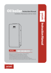
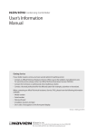
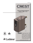
LST-58K Contents User manual Safety Instructions 4 Before using the boiler 5 Notes when using 7 The structure and its description 11 Safety device 13 Room thermostat 14 Operation and display panel 15 Room Thermostat on/off 15 Room Temp. mode 16 Heating Water Temp. Mode 17 Timer Mode 18 Power Heating Mode 19 Outing Mode 19 Hot Water Mode 20 Remote Operation by telephone 21 Daily checkup 23 Cleaning the boiler 24 Error code 25 How to locate troubles and solve 26 Safety Instructions Safety-related messages and instructions have been provided in this manual and on boiler to warn you and others of a potential injury hazard. Read and follow all safety messages and instructions throughout this manual. It is very important to understand these safety section for operating, installing and servicing of boiler. This is safety alert symbol. It is used to alert you to potential personal injury hazards. Obey all safety messages that follow this symbol to avoid possible injury or death. DANGER Indicates an imminently hazardous situation which, if not avoided, could result in severs injury or death. WARNING Indicates a potentially hazardous situation which, if not avoided, could result severe injury or death. CAUTION Indicates an imminently hazardous situation which, if not avoided, could result in minor moderate injury. Meaning of symbols in the guide for use Use of fire forbidden 4 Make ground Dismantling arbitrarily is forbidden Dangerous electric current Touching is forbidden Before using the boiler WARNING Be sure to check the fuel prior to use. Use of the oil, other than the one specified on the name plate on the front of the boiler, may result in a fire or explosion. Be sure to check the power supply. The power supply, if higher or lower than the one specified son the front of the boiler, may cause a fire. Never place any inflammable and combustibleobjects near boiler. Highly inflammable materials, such as volatile oil or alcohol, may cause a fire during ignition of boiler. Use of boiler for drying cloths may result in a fire. Check if the chimney pipe (chimney) is incorrectly connected or pulled out. If the chimney pipe (chimney) is incorrectly connected with the boiler, exhaust gas may flow into the indoors during operation, which may cause a carbon oxide poisoning. 5 CAUTION The fuel shall be kept in a place without direct sunlight, free from the impact of oil, fire, rain, or dust. Be sure to close the oil tank lid. Any foreign object in the oil tank may cause the deteriorated combustion, boiler malfunction, or the shortened life of th boiler. Check if water is in the makeup water tank. When the water is insufficient to operate the boiler, the makeup water lamp (red) on the controller will light. Check if there is any water leak in the heating and the hot water pipes of the boiler. 6 Notes when using WARNING Close all the boiler room doors leading to the indoors before use. Exhaust gas, if flowing into the indoors, may cause a carbon oxide poisoning. Do not stop up the air intake and the vent to prevent a draft in the winter. Incomplete combustion due to oxygen deficiency may lead to a carbon oxide poisoning. Do not adjust the damper (air controller) on the burner at will. Adjustment of the damper on the burner at will may cause a fire due to incomplete combustion. Do not adjust the pressure of the gear pump at will. Adjustment of the damper on the burner at will may cause a fire due to incomplete combustion. 7 CAUTION Check if there is any oil leak on the oil tank, the oil pipe, and the boiler (inside/outside). Operation of the boiler, with oil leak or stagnant oil, may cause a fire. When the boiler is operating or right after the boiler is turned off, do not touch the portions near the vent or the chimney pipe (chimney). Hot temperature on the chimney pipe (chimney) or nearby the vent may result in a burn. Use the boiler only for heating and supplying hot water. Use of the boiler for drying clothes may result in a fire. Use of the boiler for cooking may result in a personal injury. Do not insert several power plugs into one power outlet. Several power plugs inserted into one power outlet may cause a fire. 8 CAUTION Do not touch the power cord with wet hands. An electric shock may be caused. Do not make a short circuit between the low water level sensor wire and the ground wire inside the panel. Failure to detect the level (water) inside the boiler may result in malfunction of the boiler. Replace the fuse, if burnt out, with the one complying with the specifications. (Refer to the Electric wiring diagram) Random use of a non-rated fuse may cause a fire. Disposal and replacement of the boiler, if necessary, shall be performed by the installation personnel. Random disposal may result in a safety accident, especially to children or the old and the weak. 9 CAUTION Open the distributor valve and the oil middle valve when you go outside in the winter. The boiler shall keep operating not to get frozen or burst during the winter. If the distributor valve or the oil middle valve is closed, the boiler stops operation, which may cause the boiler and pipeline implosion. Never shut off the power supply, nor set the power switch at the off position in the winter. Failure of the anti frost function may result in implosion of the boiler and its pipeline. Please submit a request for inspection of your unit at least once a year. Please receive A/S regular inspection at least once a year from the dealer where you purchased the unit for safe and lengthened use of your boiler. Consultation with the installation personnel With any abnormality in the boiler, the checkup lamp on the controller will light, and the check lamp on the room temperature controller will be blinking. Then, press the restart button 2 to 3 times for reoperation. If any abnormality still exists consult with a selling agency where near your town, or where you purchased from. 10 The structure and its description Boiler LST-58K 11 Burner KPO-50B-Navien LST-58K ූFlame detector : to detect the flame of the burner for safe burner operation. ූGear pump : This device sucks and pressurizes oil for combustion. ූAir damper : to adjust the air volume for the fan. ූIgnition transformer : to generate high voltage to ignite the fuel ූElectrode : to ignite the fuel with the high voltage from the ignition transformer. Do not touch the electrode when the power is on, as electricity is flowing through the electrode. ( Warning) ූFan motor : to circulate the fan to supply air for combustion. ූNozzle : to spray the fuel to be ignited. 12 Safety Device 1. Safety device for power failure This device automatically shuts off the oil to stop operation during power failure. 2. Safety device for power recovery When the boiler recovers from power failure, this device helps the boiler to automatically re-start for normal operation (which functions for 2 hours). 3. Non-ignition protection device (Flame detection) ූThis device automatically shuts off the oil supply when the boiler does not ignite. ූThis device also shuts off the oil supply automatically, when the flame goes out during normal combustion. 4. Quasi flame protection device This device stops boiler operation, when there is any flame remaining inside the boiler prior to normal operation. 5. Anti overheat device (for prevention of hot temperature) This device shuts off the oil supply for stopping the boiler operation automatically, when the heat exchange is overheated. 6. Low water level shut off device This device indicates that the boiler has run out of water and stops the boiler operation. 7. Temperature controller protection device This device stops the boiler operation, if there is any abnormality in the temperature sensor. 8. Anti frost device This device automatically circulates water and raises the water temperature in order to keep the boiler from getting frozen with the anti frost function, when you go outside in the winter. 9. Short circuit protection device This devices stops boiler operation by cutting off the fuse, when there is any abnormality in the wires (short circuit) inside the boiler or when the over current is generated to exceed the rated capacity of the fuse. 10. Lightening and static electricity protection device The protection device to prevent a lighting strike (lightening) and the electrostatic discharge is supplied in the controller. 13 Room Thermostat (LCR-2D) LCD Display Indicating each function and status UP/DOWN Temp. & Timer Mode Outing Mode Outing Setting Mode MODE Select Mode Power Hot Water Room Thermostat Power ON/OFF Hot Water Mode LCD 14 Temperature Operation Indicator Hot water Mode Outing Mode Timer Heating Heating Water Temp. Room Temp Power Heating Operation and display panel Operation and display panel (KDC-106M) Heating temp. LED indicate the temp. of heating water, and occurrence of trouble displayed the failure code. 02. LOW WATER LEVEL 03. MISFIRE 04. PSEUDO-FLAME 05. TEMP. SENSOR FAILURE 12. MISFIRE IN COMBUSTION 16. BIMETAL OVERHEAT Room Thermostat On/Off Press the power button. LCD is on when pressing the power button. Hot water and heating operation stops and LCD is turned off when pressing the power button again. 15 Room Temp. Mode Press the Mode button repeatedly, until is displayed. Set the heating temp. with +/- button. blinks when selecting Room Temp. Mode When blinks, set the desired heating temp. between 10~40丯 by adjusting +/- button, after a while, it is automatically saved. Heating temp. can be set by 1丯. After the setting is done, is on and current room temp. is displayed. CAUTION If a room thermostat is programmed with Room Temp. Mode and it is placed in the following places when using Room Temp. mode, it may cause some errors to recognize temperature. 1. Frequently opened and closed door and drafty place. 2. A place where direct sunlight is effected and high humidity. 3. A place under direct influence from heat, such as radiator. In that case, Heating Water Temp. is recommended. 16 Heating Water Temp. Mode Press the Mode button repeatedly, until is displayed. Set the heating temp. with +/- button. blinks when selecting Heating Water Temp. Mode When blinks, set the desired heating temp. between 40~80丯 by adjusting +/- button, after a while, it is automatically saved. Heating temp. can be set by 1丯 After the setting is done, is on and current heating water temp. is displayed. 17 Timer Mode Timer Mode is a function that boiler repeatedly operates 20- minute stop and again that can be set in the range of hour 0~9, 50 minutes. Press the Mode button repeatedly, until is displayed. blinks when selecting Timer Mode. CAUTION 18 Set the heating stop time with +/- button When blinks, set the desired heating stop time. It can be set by 10 min., up to 50min in the range of hour 0~9 by adjusting +/- button, after a while, it is automatically saved. After the setting is done, is on and current room temp. is displayed. Heating stop time ‘0’ means boiler is continuously operates. In this case, heating temperature keeps increasing. so, please be careful. Power Heating Mode Press the Mode button repeatedly, until is displayed. When selecting Power Heating, is displayed and it is combustioning for 30 minutes continuously. After 30 minutes, it returns to previous heating mode. Outing Mode Use this function when operating the boiler with minimum capacity without heating and there is no one at home. Press button will be displayed and Outing Mode will be set. Press the MODE button and select the desired heating to cancel the Outing Mode. 19 Hot Water Mode Use this function only when hot water is needed. Press button. will be displayed and Hot Water Mode will be set. Press the MODE button and select the desired heating to cancel the Hot Water Mode. CAUTION 20 1. Please be careful that infants and young children do not use hot water without a guardian for safety. 2. When others use hot water, do not change the hot water temp. setting for safety. Remote Operation By Telephone With phone network, heating function of room thermostat can be set. Activating the boiler 1. Press "#" button 3 times. 2. Hang up the phone, when hearing 'beep-beep' sound. AM AM 1 2 3 4 5 6 7 8 9 * 0 # # 1 2 3 4 5 6 7 8 9 * 0 # # # # CM CM The boiler is operated with ‘Power Heating Mode‘ for 30 minutes and returns to the previous mode (If the room thermostat is off, return to Outing Mode.) Suspending the boiler 1. Press "#" button 3 times. 2. Hang up the phone, when hearing ‘ 'beep-beep-beep' sound. Then, it changed to Outing Mode AM AM 1 2 3 4 5 6 7 8 9 * * TIP 0 # CM * * * 1 2 3 4 5 6 7 8 9 * 0 # CM When using outside telephone, call the phone, after the call is connected to the boiler after ringing the preset number of times, you will hear a 'beep' sound. Then, manipulate the buttons as described above. 21 When altering the number of ringing 1. Press"0" button 3 times. 2. 'beep-beep-beep-beep' sound will be ringing 4 times. AM AM 1 2 3 4 5 6 7 8 9 * 0 # 0 1 2 3 4 5 6 0 7 8 9 0 * 0 # 0 CM CM 3. Press a button you select out of 5,6,7,8,9, or 0 three times. AM AM 1 4. After 'beep-beep-beep-beep-beep' sound, hang up the phone. 2 3 1 2 3 5 6 4 5 6 4 7 8 9 7 8 9 * 0 # * 0 # CM CM CAUTION 22 1. If you don't press any buttons for 10 seconds or longe after pressing '#' or '*' button, the telephone will automatically hang up. 2. Make sure to hang up the phone after hearing activation or suspension signal. 3. If you don't hear the 'beep' sound while using it, manipulate it again slowly. Daily checkup 1. Check if there is any combustible object nearby the boiler chimney pipe (chimney) 2. Check if chimney pipe(chimney) is crushed, filled with water, clogged or burst and if the end of the chimney pipe(chimney) is in a place and a direction not to have damage on other houses and people owing to the wind or other impacts. 3. Check if the connection points on the in take and exhaust pipes (exhaust pipe, chimney pipe) are secured, if the chimney pipe(chimney) is clogged, and if there is any leak due to rusty portions. 4. If there any abnormality still exists, call the agency where you purchased from, and consult with a installation personnel. 5. Always keep the boiler clean. 6. Check if the any oil leak in the oil tank, the oil pipe, or the boiler. 7. Check if there is any water leak inside the boiler (inside or outside) or the pipe. Water discharge from the oil tank Open the water discharge valve on the oil tank to remove water periodically. It is dangerous to fully open the water discharge valve, as a large amount of oil may flow out of the oil tank. You do not have to fully open valve, as there is only a small amount of water to remove. 23 Cleaning the boiler Cleaning the oil filter If the oil filter is dirty, stop operation of the boiler, close the oil valve, and remove dust and rust below the oil filter cup. 1. Turn off the boiler. 2. Separate the oil filter cup connected to the flexible hose nearby the inlet of the gear pump, by turning the cup counter-clockwise. 3. Separate the strainer screen by pulling it out downward. 4. Clean the strainer screen and inside the oil filter cup using the clean boiler oil or the light oil. <Figure 2> <Figure 1> <Figure 3> ȄDo not forget to wear gloves while cleaning. Cleaning the flame detector Dirt and fume deposits on the photoelectric tube causes deteriorated sensitivity of the tube, and the photoelectric tube may fail to detect the flame, which eventually leads to failure of combustion. 1. Pull out the flame detector (Black) attached to below the burner. 2. Wipe the glass surface of the flame detector with clean cloth. 3. Fit the flame detector into the burner until you hear a snap sound, after cleaning. <Figure 1> <Figure 2> ූBe sure to turn the power on, while cleaning the flame detector. ූNever wipe the flame detector with wet cloth or oil. ූDo not pull the wire out while separating the flame detector. 24 Error code When an error occurs, the LCD shows one of the following numeric error codes with letter 'E'. Code Problems Factors Operation Fan Circulation Pump 02 Low water level Not enough water to operate the unit OFF OFF 03 Ignition a failure Fa Fail to ingniting OFF Controling the temperature 04 Flame-sensor (Lower gas pressure) If detecting any flame in the chamber during pre-purge and post-purge OFF Controling the temperature 05 Heating sensor wire disconnected Heating water sensor is disconnected OFF ON 06 Short circuit of heating Heating water sensor is in a short sensor circuit OFF ON 12 Flame failure in combustion Failure of flame is occurred during the combustion OFF Controling the temperature 16 Mechanical overheat Abnormal statue of heating water temperature OFF ON 25 How to Iocate troubles and solve If there is any abnormality in the product, check the following before consulting with the installation personnel. If the check lamp light is on to indicate an abnormality, take proper actions by symptoms as presented in the following, and restart the boiler. (Re-insert the power plug or set the restart switch at ON to re-operate the boiler.) If the boiler does not operate, call the nearby any distributors. Symptoms Causes Actions The fuse is burnt out. Replace the fuse. Power failure. Wait for the power recovery. The plug contact failure. Consult with the installation personnel. The power plug is not connected. Connect the power plug. The room temperature is higher than the designated temperature. Increase the temperature on the room temperature controller supplied in the room. The temperate set by the boiler temperature controller is too low. Increase the temperature on the boiler temperature controller. The heating pipe has run out of water, or the makeup water valve is closed. Fill the makeup water The low water level connection wire(Yellow) on the controller is incorrectly connected or short-circuited. Consult with the installation personnel.. The earth wire on the controller (Red)is incorrectly connected. Consult with the installation personnel.. Flame is not detected. Consult with the installation personnel.. The ignition spark is not generated. Consult with the installation personnel.. Sensor The sensor wire on the controller is incorrectly connected or short-circuited. Consult with the installation personnel.. Overheat The heat exchanger is overheated. The heating pipe is clogged. Consult with the installation personnel.. The valve on the heating pipe is closed, or the pipe is clogged. Consult with the installation personnel.. The heating pipe is filled with air or has a water leak. Consult with the installation personnel.. The circulation pump does not operate. Consult with the installation personnel.. The boiler operates normally, but hot water is not supplied. The valve on the hot water supply pipe is closed, or the pipe is clogged. Consult with the installation personnel.. Too much noise is generated during ignition and combustion The duct on the chimney is incorrectly installed. Consult with the installation personnel.. The chimney is clogged. Consult with the installation personnel.. The Power lamp does not light. (No indication of power supply) The Power lamp is on, but the boiler does not work The boiler does not operate. Makeup water Check The boiler operates normally, but the heating does not work. 26 Safety Instructions Safety-related messages and instructions have been provided in this manual and on boiler to warn you and others of a potential injury hazard. Read and follow all safety messages and instructions throughout this manual. It is very important to understand these safety section for operating, installing and servicing of boiler. This is safety alert symbol. It is used to alert you to potential personal injury hazards. Obey all safety messages that follow this symbol to avoid possible injury or death. DANGER Indicates an imminently hazardous situation which, if not avoided, could result in severs injury or death. WARNING Indicates a potentially hazardous situation which, if not avoided, could result severe injury or death. CAUTION Indicates an imminently hazardous situation which, if not avoided, could result in minor moderate injury. Meaning of symbols in the guide for use Use of fire forbidden 28 Make ground Dismantling arbitrarily is forbidden Dangerous electric current Touching is forbidden Outside drawing on the boiler LST-58K 29 Safe and correct installation Before installation WARNING Be sure to check the fuel to be used in the installation place, prior to installation. Use of the oil, other than the one specified on the name plate on the front of the boiler, may result in a fire or explosion. Be sure to check the power supply appropriate for the installation place, prior to installation. The power supply, if higher or lower than the one specified on the front of the boiler, may cause a fire. Selection of the installation place WARNING Never install the boiler in a place with inflammable objects. Highly inflammable materials, such as volatile oil or alcohol, may cause a fire during ignition of the boiler. Install the boiler in a boiler room free from the impact of rain and wind. Incomplete combustions, resulting from rain and wind, may eventually lead to a carbon oxide poisoning. 30 Never install the boiler in a moist or enclosed place such as a bathroom, a toilet. Incomplete combustion, caused by oxygen deficiency, may lead to a carbon oxide poisoning. Installation in the above place may also cause earlier product malfunctions. Never install the product in a place with corrosive gas such as ammonia, chlorine, sulfur, acids. Corrosive gas may damage the boiler and cause incomplete combustion, eventually leading to a carbon oxide poisoning. Other considerations Naver install the boiler in the following place. Do not install the boiler near the electric equipment. Do not install the boiler in an uneven or unstable place. Do not install the boiler in a place with highly combustible materials. Do not install the boiler in a place inadequate for safe installation of the oil tank. Do not install the boiler in a place with special chemical agents (generating combustible or corrosive gas). Do not install the boiler in a place inappropriate for escaping to the stairway or the exit. Do not install the boiler in a place which is not well drained. Do not install the boiler below the shelf with unstable objects. Do not install the boiler in a place inadequate for performing maintenance of the boiler after installation. Do not install the boiler in a place with noise and air pollution. Do not install the boiler in a place where the wind generated from a vent, a range, or a hood has an impact on air intake and exhaust. Do not install the boiler in a place which is not well-ventilated. Do not install the boiler in a place with strong wind. Do not install the boiler in a place inappropriate for installing the chimney pipe (chimney). ȄBe sure to install the boiler in a sufficient place for check urepair of the boiler. A space of more than 1m shall be providedfront of the boiler, in order to perform maintenance and checks. 31 Boiler installation Install the boiler on the surface with a structure capable of enduring the load of the boiler (weight). (Refer to the specifications presented in the user’s manual.) Install the boiler in a horizontal, upright position so that the boiler does not lean toward one side. Installation shall be made for the front side of the boiler to face forward. Install the boiler to be fixed on the floor, in order to prevent vibration during operation. Sufficient light shall be provided with the boiler room in order to help to observe the boiler equipment by sight and offer the warranty service for the equipment. Precautions for boiler installation in a dedicated boiler room Be sure to install the boiler in the dedicated boiler room. (The boiler room shall be designed for the gas emitted from the boiler not to flow into the living room, and the wall between the boiler room and the living room shall be made of the fireproof materials, except for the entrance / exit door.) The dedicated boiler room shall not be equipped with the ventilating fan which causes the negative pressure (the pressure lower than the atmosphere pressure). The dedicated boiler room shall not be equipped with the exhaust duct of the gas range (hood) which leads to air flowing in and out of the living room and the kitchen. Installation of the boiler shall not be made nearby the place for storage and treatment of the combustible or inflammable objects. A sufficient space shall be provided for boiler installation as presented in the following figure, in order to perform the control, combustion, check-ups and repair of the boiler. The top of the boiler body shall be kept at least 1.2m away from the structures such as the ceiling and the piping. The boiler body shall be kept at least 450mm away from other structures on the side of the boiler such as the wall and the piping. The front of the boiler shall be kept at least 1m away from the structures in front of the wall. 32 The boiler shall be kept away from the nearby combustible objects, as illustrated in the following figure. Precautions for boiler installation in the outdoors Appropriate protection facilities such as the casing shall be provided for the boiler to prevent the rain from permeating into the boiler. The waterproof treatment shall be applied to the exposed insulation materials or lagging. Proper measures shall be taken to protect the water pipe outside the boiler from getting frozen. Proper measures shall be taken for combustion of the boiler to be protected against snow, rain and wind. 33 Electric wiring installation WARNING The electric wiring installation shall be performed to comply with the power supply of the product. The power supply, if higher or lower than the one specified on the name plate on the front of the boiler, may cause a fire. CAUTION Do not connect the power supply to the boiler until the electric wiring installation is completed. With the power supply on, the electricity flowing through the boiler may cause an electric shock. Install the power outlet in a place free from the impact of rain and moisture. Electric leakage, if caused by rain and moisture, may lead to a fire. 34 Never make a ground connection to the lightning rods and the fuel pipe. Ground connection to the lightning rod may result in a boiler malfunction. Ground connection to the fuel pipe may result in an explosive accident. Be sure to use the magnet switch for connection of the circulation pump with more than 150W. The boiler may malfunction, without the magnet switch. Correct electric wiring installation Install the electric wiring as presented in the electric wiring drawing in the installation manual. Install the dedicated power outlet for the boiler, with a length of less than the effective length of the power cord. Installation shall be made in a place where the power outlet does not get in touch with the drain valve of the boiler. Use the power outlet with a cover attached for boiler installation. The outlet shall be installed at least 300m above ground level. If the power outlet is not provided with a cover, install the outlet in a place free from the impact of rain or moisture, or in the waterproof box or the indoor distribution box. Never install a switch onto the power cord, nor use the power outlet with a switch attached. (The boiler does not operate, when the switch is set at off.) A ground connection shall be installed, if not, on the side of the power outlet. The wires of the room temperature controller shall be connected through the insulation pipe with a thickness of more than 4mm, The insulation pipe shall be installed and concealed with an upper gradient toward the indoors. ȄThe wires of the circulation pump, connected to the controller, shall not be short-circuited. 35 Fuel(oil) piping installation WARNING Check if there is oil leak or stagnant oil on the oil tank, the oil pipe, the boiler (inside and outside). The boiler operation with oil leak or stagnant oil may cause a fire. Installation of the oil tank Install the oil tank in a well-ventilated place, free from the impact of direct sunlight or rain. Install the oil tank more than 2m away from the boiler, or erect a fireproof wall between the oil tank and the boiler. If the oil tank is to be installed in a dedicated boiler room, use non-flammable materials for installation of the wall, the column, and the ceiling. Be sure to install the water drain valve in the oil tank, and perform water drain periodically. The oil tank shall be installed within 2m above and 2m below the burner of the boiler. The oil tank shall be kept more than 300mm away from the piping, the chimney, the electric breaker, and the power outlet, more than 600mm away from the electricity meter and the safety box, and more than 150mm from the wire. The piping shall be installed with its surface exposed, and securely fixed not to move on the floor. (The piping, if made of copper, stainless steel, or other anticorrosive materials without any joints, may be buried on the floor.) <The method of downward piping for the fuel storage tank> 36 <The method of piping for the fuel storage tank> Connection of oil pipeline The oil pipeline shall be securely connected to the oil tank. It shall be free from oil leakage and separably connected to the oil tank. The connection points of the oil pipeline shall not be easily deformed or separated. The oil pipeline shall be made of metal or copper. The pipe size of the oil pipeline shall be larger than that of the flexible hose. The oil pipe shall be installed as short as possible and with less resistance so that the burner may perform normal intake. Dispersivity foreign objects in the oil pipeline will obstruct normal combustion. Remove the foreign objects inside the oil tank and the oil pipeline prior to connection of the oil pipeline with the boiler. Connect the flexible hose of the boiler with the oil pipeline using the dish nipple. (The dish nipple is supplied with the boiler.) The oil pipeline shall be installed evenly without any raised or lowered portion so that air is not stagnant in the pipeline. Be sure to connect the fuel line of the boiler in a multiple pipe system. ȄIf the fuel line is connected in a single pipe system, be sure to perform air vent work after the fuel piping installation. (Refer to the method of air vent work presented in the installation manual.) 37 air vent work (the single piping system) 1. Loosen the air vent screw on the upper side of the oil filter using a Philips head screwdriver. After air vent is completed and oil is discharged, tighten the air vent screw. (This method is feasible only when the oil tank is placed above the oil filter.) 2. As the air is not sufficiently vented when the oil tank is placed below the oil filter, loosen the air vent bolt on the gear pump and turn the boiler power on. When the gear pump starts operation, the air will be vented. Then, the check lamp on the controller will light, and the boiler will stop operation. 3. Press the Restart button on the controller to repeat the above operation. Then, the entire amount of air will be vented and oil will be discharged. Tighten the air vent bolt and press the Reset button again. The burner will be operating for ignition. <Gear pump supplied by DANFOSS> <Gear pump supplied by SUNTEC> Ȅ Considerations for the air vent work In case of the multiple pipe system, the air vent work is not necessary, as the air is automatically vented toward the return pipe. Care shall be taken to prevent oil from flowing on the floor during the air vent work. Do not loosen the air vent bolt of the gear pump fully, as too much oil may flow out of the bolt hole. If the air vent bolt is not on the gear pump, loosen the bolt on the return side for air vent and tighten the bolt immediately after oil starts to be discharged. Wear gloves to protect your hands from oil. 38 Example of installation of the oil pipe (KPO Burner) 1. Multi piping system (2-pipe type) Use this system when the oil tank is installed above, below, or at the same height as the boiler. The piping method is to connect the gear pump inlet to the pipe on the lower side of the oil tank and connect the additional return pipe to the return pipe of the gear pump in order to return the oil to the tank. 2. Single piping system (1-pipe type) Use this method when the oil tank is installed above or at the same height as the boiler. As the boiler is initially set at the multiple piping system, refer to the modification method of the gear pump, in order to modify the multiple piping to the single piping system. 3. The method of modification of the gear pump (Multiple piping systemĄsingle piping system) DANFOSS: ΗDisassemble the oil hose for return, and assemble A. Θ Open the bolt B and remove the inner screw using a regular screwdriver (-) and reassemble the bolt B. SUNTEC: Η Disassemble the oil hose for return and remove the screw using the Allen wrench. Then, assemble the bolt A. <DANFOSS> <SUNTEC> 4. In the multiple piping system, the parts 1, 2, and 3 are supplied in an assembly, and the parts 4, 5, and 6 and the bolt A are supplied separately in the parts’ pocket. 39 Heating and hot water piping installation CAUTION The exposed pipes shall be heat insulated with the insulation material. The exposed pipes may get frozen in the winter. If the water supply pipe is frozen, the hot water is not supplied, and when the heating pipe has run out of water, the water is not supplemented. Consequently, the boiler can not operate normally. Fix the parts of the boiler pipes with appropriate tools, prior to piping installation. Do not exert excessive force on the pipe during the installation. Damages on the parts may cause a water leak. Be sure to use the insulation flange on the heating inlet and outlet in case of installation of the copper pipe. (the hot water inlet and outlet for a boiler dedicated for hot water supply) Failure to use the insulation flange may cause rapid corrosion (rusty water). We do not take the responsibility of the problems arising from failure to use the insulation flange. Do not use water, other than the tap water, for the boiler. Salt content in the sea water or spa water may accelerate corrosion and shorten the life of the boiler. We do not take the responsibility of the problems caused by using water, other than the tap water. 40 Precautions for piping installation Install the pipes as illustrated in the standard pipe drawing. Failure to install the pipe as illustrated in the standard piping drawing may deteriorate the efficiency of the boiler and the circulation of the heating water, which may result in a boiler malfunction. A separable union connection or a nut connection shall be performed on the connection points. The piping materials shall comply with the Standard of each nation. Do not use the metals with different electric potentials to install the piping for a dedicated boiler for hot water supply, (For example, do not install the copper pipe in the iron boiler.) which may cause galvanic corrosion, eventually generating rusty water. Do not use the rubber hose for the faucet, for piping connection. Be sure to remove foreign objects inside the pipe prior to the piping installation. Install the piping correctly for the water supply, the hot water supply, the heating, and the drain. If the water supply pressure exceeds the allowable working pressure specified on the name plate, be sure to install the depressurizing valve. Proper measures shall be taken against a water leak through a water leak test for the entire piping after completion of installation. The entire pipelines, except for the fuel pipe, shall be provided with heat insulation to protect against frost, after completion of installation. (Especially, care shall be taken for the water supply and the hot water pipes.) Be sure to install the pressure release pipe for installation of the boiler. If it is impossible to install the pressure release pipe, the safety valve, operating below the maximum allowable working pressure of the boiler, shall be installed. (The maximum allowable working pressure of the boiler is presented in the “Specifications”.) Never install the valve and the check valve in the pipeline where the pressure release pipe or the safety valve is installed. Select the boiler expansion tank, if necessary, with a capacity suitable for the boiler in use. Do not use the water inlet instead of the drain, and vice versa. If the water supply is to be made to the boiler from the rooftop water tank, be sure to install the water supply pipe in the auxiliary tank, separate from the rooftop water tank, for water supply to the boiler. Install the pipes as illustrated in the standard pipe drawing. 41 Precautions for piping installation Precaution for the piping installation for the combi boiler for heating and hot water supply / the dedicated boiler for heating LST-58K Open piping system Be sure to comply with the instructions presented in the “Considerations in common”. Be sure to install the air vent valve in the distributor. The return distributor shall be installed below the heating inlet on the boiler. The pressure release pipe shall be installed to exceed 25A. Never supply the water with a pressure higher than the maximum allowable working pressure of the boiler specified on the name plate, nor connect the water pipe directly for the piping. The reverse flow of the heating water into the expansion tank, while operating or stopping the circulation pump, results from too much air in the pipe. (Open the valve in the distributor one by one and remove the air from the pipe, while operating the circulation pump.) The expansion tank shall be installed at least 1.5m above the heat dissipation surface in case of the upward type, and at least 1.5m above the top of the boiler in case of the downward type. The piping installation shall be performed not to mix the heating water and the hot water. Closed piping system Be sure to comply with the instructions presented in the “Considerations in common”. Be sure to install the strainer, the depressurizing valve, the check valve, the safety valve, and the enclosed expansion tank, in order to directly connect the boiler to the water pipe. Be sure to install the depressurizing valve and the check valve in the water supply pipe. Install the air vent on top of the heat dissipation surface to facilitate air vent. Be sure to install the strainer in the water supply pipe, in order to prevent metal and foreign objects from flowing into the water supply pipe. Be sure to install the safety valve. Be sure to install the enclosed expansion tank with an appropriate capacity. 42 Standard piping drawing Open expansion - Combi boiler Closed expansion - Combi boiler 43 Room Thermostat Installation 1. Fix the bracket by using bolts. 2. Connect firmly the two wires from the boiler to the screws on the back side of the room thermostat. 3. Connect firmly the two wires from the telephone code to the screws on the back side of the room thermostat. 4. Fix the room thermostat on the bracket. Bolier Main Controller R/C TP Telephone Connections 47 CONVERTER-CV2 Check point for safety 1. Check the electric voltage before you operate the boiler. 2. Tele-room controller can be adapted to voltage DC 24-31V form the main controller of boiler. 3. Make sure to connect the electric port properly. One is far room controller , the other is for telephone. Check point for fixing 1. Fix the room controller on the wall of room or living room. The height is about 1.5m. 2. Fix on the properly spot to sense the room temperature. 3. Avoid to fix near the heater or under the sun light, this can cause the torsion of the case and do a harm to the electric parts inside the case. 4. Avoid to fix in the place there is dirty, humid, this can do harm to the electric parts inside the case. Check point for usage 1. You had better take care to prevent the metallic parts (Needle, Coin) or in flammables (Paper, Match stick) form entering into the air vent hole of the case. This can make a short-circuit or fire. 2. Do not open the case, and treat your self. 3. Be careful the power line not to exposed in the room. 4. Keep out form the volatiles (Thinner, Benzene, Solvent…) 5. Before you polish the room controller , plug the power cord out and use a smooth cloth. Description & Function Signal lamp £Run (Normal operating) ¤Hot w+ater supply ¥Heating mode ¦Boiler stop §Check (Operating error) ¨Power on/off Operation & Sensor ©7HPSHUDWXUH(UURUGLVSOD\ ª%RLOHUZDWHUWHPS FRQWURONQRE «3RZHU5HVHWVZLWFK 48 Fixing & Wiring 1. Connect firmly the room controller wire(2 Line) form the boiler , to the room controller port in the back of the room controller. 2. Connect firmly the KD-SP wire to the telephone port in back side of the converter-CV2 3. Fix the room controller firmly on the wall, using the converter-CV2 bracket. 4. Wiring Adaptor Telephone L1 L2 Telephone line Main Controller Power (Ac 220V) Boiler Hot Water Flow Sensor 49 Multi Floor System M.F.S Converter (KDC-5P) DR-5P TMR-5P Fan 3rd Fl. Valve Radiator M.F.S Converter (KDC-5P) DR-5P TMR-5P Fan 2nd Fl. Valve Radiator M.F.S Converter (KDC-5P) DR-5P TMR-5P Fan 1st Fl. Valve Radiator CONVERTER-CV2 VALVE Actuator : Erie VT2325G13A01A AC24V 2WAY WATT6.5 water flow detector sensor Main Controller Cold Water KDC-104P KDC-106M Pump Boiler Power(AC220V) Roomcon Terminal No. 50 Multi Floor System Room Converter 161 149 139 4-Φ4.5 HOLE KyungDong 4 11 10 3 2 1 9 8 7 Green AC250V 5A 87 5 13 12 45 (ACPOWER VOLT 100VA) 50 6 VALVE or FAN ROOMCON -6P,7P Red 53 (AC24V 6VA)≥ Blue Brown M.F.S ROOM CONVERTER WIRE DRAW VALVE White Orange AC POWER INPUT (10, 21) KDC-104P, 207TP KDC-5P (AC220V) 46 68 <KDC-5P> Converter –CV2 51 Check point for test operation 1) Check if the boiler is installed correctly. Η Check if the floor surface is made of strong, flat, and non-flammable materials such as concrete and if the surrounding area is also made of non-flammable materials. ΘCheck the air intake and the vent in the boiler room. Ι Check if the boiler room is provided with a drain, and if the boiler is equipped with the drain valve. Κ Check if the boiler and the pipeline are heat insulated to prevent frost damage. Λ Check if the chimney pipe is correctly installed Μ Check if rain does not permeating through the penetration portion of the exhaust pipe. Ν Check if the boiler is evenly installed. Ξ Check if there is water leakage near the piping connection joint. Ο Check if there is any leakage near the oil pipe connection joint. Π Check if the pressure release pipe or the safety valve are installed in the boiler. Ρ Check if the ground wire is connected. (If the ground connection is made on the fuel pipe or the lightning rod, change the position.) Check if the fuel is the same as the oil specified on the name plate of the boiler. Σ The oil tank shall be installed in a place free from the impact of fire, rain, and dust, and without the direct sunlight. Check if there is a partition wall between the place of the oil tank and the boiler room. 52 Test operation Open the water supply valve to supplement water in the boiler. - The water supply pressure shall be kept to less than the allowable working pressure, specified on the name plate of the boiler. - Upon completion of water supplement, the makeup water lamp on the controller goes out. Connect the boiler to the power supply. Do not touch the power cord with wet hands. Remove the remaining air from the fuel line. You may not remove the air in case of using the multiple pipe system. Push the power switch of the boiler controller to on. Open the valve on the fuel line. Set the room temperature controller S/W at the operation mode. After ignition of the boiler, check the combustion mode and the heating circulation mode. Η Set the temperature on the temperature controller of the boiler controller ĄSet the room temperature controller button (High speed, Temperature, Time) at ON ĄOperation of the burner fanĄOperation of the ignition transformer ĄOpen the electronic valveĄCombustionĄFlame detection ĄON/OFF in accordance with the temperature setting (operation of the circulation pump) ΘCheck if the boiler stops operation and the circulation pump is operating, by adjusting the temperature controller of the boiler controller. Press the “Hot water” button on the room temperature controller in order to check if the circulation pump stops operation and hot water is supplied. Press the “Outing” button on the room temperature controller to check if the boiler stops operation. 53 Maintenance Yearly appliance check and maintenance The followings checks and maintenance activity should be performed at least one time per year : Cleaning of the burner Visual inspection of the exhaust duct for wear or corrosion checking Correct ignition and detection Correct burner setting in heating and domestic hot water production Correct operation of the main switch upstream the boiler Correct operation and adjustment of the boiler regarding : - Activation of the heating control system - Activation of the domestic hot water production system Checking of the correct activation of the detection control system; its activation must be shorter than 10 seconds. Watertight of the boiler heating and domestic hot water production circuit; no leakage or water oxidation have to appear around the coupling. Visual Checking that the outlet of the pressure relief valve is not blocked. Visual checking that the safety and control devices have not been tampered or short- circuited; in particular: - Temperature safety limit thermostat Visual checking of the electrical system; in particular: - Electrical power cable must be no damaged and properly blocked. - No trace of blackening or burning must be exist anywhere. 54 IU08#2#IU0<D#2#OFU05G IU08K DU06P Electric wiring diagram 55 The Specification Model Navien LST-58K Heating output kcal/h (kW) 50,000(58.5) Hot water output kcal/h (kW) 50,000(58.5) Classi cation Hot water supply capacity( 40 ) 21 Purpose Heating/Hot water ciency % Fuel 89.5 Heating oil(Light oil) 3.5 (0.343) Maximum allowable working pressure Heat transfer area 1.83 Heating area 330.6 38 Volume of pipe water kg Weight 1Φ, 220V, 50Hz Power supply KPO-50B Burner Model no. kg/h 5.5 mm 491 mm 767.6 mm 910 Heating inlet outlet A 40 Drain A 40 Discharge outlet A 40 Hot water inlet A 20 Φ 148 Fuel consumption Width Product Depth + Burner size Height Piping size 94 Chimney size Temperature of the exhaust gas 250 or less The specifications presented in this manual are subject to change without notice for quality improvement. 56 memo 57 memo 58 20009014E BO-E-M-10-02 2013.05.23