1
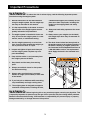
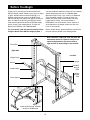
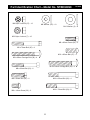
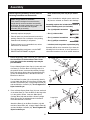
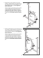
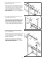
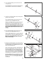
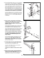
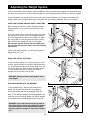
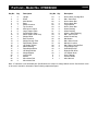
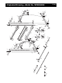
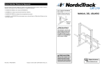
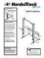
¨
Model No. NTBE04990
Serial No.
Write the serial number in the space
above for reference.
USERÕS MANUAL
Serial
Number
Decal
QUESTIONS?
As a manufacturer, we are committed to providing complete
customer satisfaction. If you
have questions, or find that
there are missing parts, we will
guarantee you complete satisfaction through direct assistance from our factory.
TO AVOID UNNECESSARY
DELAYS, PLEASE CALL
DIRECT TO OUR TOLL-FREE
CUSTOMER HOT LINE. The
trained technicians on our customer hot line will provide
immediate assistance, free of
charge to you.
CUSTOMER HOT LINE:
1-888-825-2588
Mon.ÐFri., 6 a.m.Ð6 p.m. MST
CAUTION
Read all precautions and instructions in this manual before
using this equipment. Save this
manual for future reference.
Patent
Pending
Visit our website at
www.nordictrack.com
new products, prizes,
fitness tips, and much more!
¨
Table of Contents
Important Precautions . . . . . . . . . . . . . . . . . . . . . . . . . . . . . . . . . . . . . . . . . . . . . . . . . . . . . . . . . . . . . . . . . . . 3
Before You Begin . . . . . . . . . . . . . . . . . . . . . . . . . . . . . . . . . . . . . . . . . . . . . . . . . . . . . . . . . . . . . . . . . . . . . . 4
Part Identification Chart . . . . . . . . . . . . . . . . . . . . . . . . . . . . . . . . . . . . . . . . . . . . . . . . . . . . . . . . . . . . . . . . . . 5
Assembly . . . . . . . . . . . . . . . . . . . . . . . . . . . . . . . . . . . . . . . . . . . . . . . . . . . . . . . . . . . . . . . . . . . . . . . . . . . . 6
Adjusting the Weight System . . . . . . . . . . . . . . . . . . . . . . . . . . . . . . . . . . . . . . . . . . . . . . . . . . . . . . . . . . . . . 11
Ordering Replacement Parts . . . . . . . . . . . . . . . . . . . . . . . . . . . . . . . . . . . . . . . . . . . . . . . . . . . . . .Back Cover
Limited Warranty . . . . . . . . . . . . . . . . . . . . . . . . . . . . . . . . . . . . . . . . . . . . . . . . . . . . . . . . . . . . . . . Back Cover
Note: A Part List/Exploded Drawing is attached in the center of this manual. Remove the Part List/Exploded
Drawing before beginning assembly.
NordicTrack¨ is a registered trademark of ICON Health & Fitness, Inc.
2
Important Precautions
WARNING: To reduce the risk of serious injury, read the following important precautions before using the weight system.
1. Read all instructions in this manual before
using the weight system. Use the weight system only as described in this manual.
a barbell and weights (not included). Do not
place more than 310 pounds, including the
barbell, on the weight gliders and safety
spotters.
2. It is the responsibility of the owner to ensure
that all users of the weight system are adequately informed of all precautions.
12. Always set both safety spotters at the same
height.
3. The weight system is intended for home use
only. Do not use the weight system in a commercial, rental, or institutional setting.
13. Always secure your weights (not included)
with weight clips when they are mounted on
the barbell.
4. Use the weight system only on a level surface. Cover the floor beneath the weight system to protect the floor or carpet.
14. The decal shown below has been placed on
the weight system in the indicated location. If
the decal is missing or illegible, please call
our Customer Service Department toll-free at
1-888-825-2588 to order a free replacement
decal. Apply the decal in the indicated location.
5. Inspect and tighten all parts each time you
use the weight system. Replace any worn
parts immediately.
6. Keep children under 12 and pets away from
the weight system at all times.
7. Keep hands and feet away from moving
parts.
8. Always wear athletic shoes for foot protection while exercising.
9. Always make sure that there is an equal
amount of weight (not included) on each side
of the barbell.
10. If you feel pain or dizziness while exercising,
stop immediately and begin cooling down.
11. The weight system is designed to support a
maximum of 560 pounds, including the user,
WARNING: Before beginning this or any exercise program, consult your physician. This
is especially important for persons over the age of 35 or persons with pre-existing health problems.
Read all instructions before using. ICON assumes no responsibility for personal injury or property
damage sustained by or through the use of this product.
3
Before You Begin
Thank you for selecting the versatile NordicTrack¨
GRT270 weight system. Whether your goal is a shapely figure, dramatic muscle size and strength, or a
healthier cardiovascular system, the NordicTrack
GRT270 will help you achieve the specific results you
want. In addition, the NordicTrack GRT270 can be
used with the optional NordicTrack¨ GRT200 weight
bench, shown in the drawing below. To order the
NordicTrack GRT200, call 1-888-825-2588
you have additional questions, please call our Customer
Service Department toll-free at 1-888-825-2588,
Monday through Friday, 6 a.m. until 6 p.m. Mountain
Time (excluding holidays). To help us assist you,
please note the product model number and serial
number before calling. The model number is
NTBE04990. The serial number can be found on a
decal attached to the weight system (see the front
cover of this manual).
For your benefit, read this manual carefully before
using the NordicTrack GRT270 weight system. If
Before reading further, please familiarize yourself with
the parts that are labeled in the drawing below.
Note: The terms Òright sideÓ and Òleft sideÓ are
determined relative to a person sitting on the
optional weight bench; they do not refer to
right and left on the drawings in this manual.
Pull-up Bar
Right Side
Left Side
Weight Guide
Upright
Barbell
Dumbbell
Storage
Rack
Weight Glider
Weight
Storage
Tube
Safety Spotter
Optional NordicTrack¨ GRT200
Model No. NTBE01490
4
Part Identification ChartÑModel No. NTBE04990
M8 Nylon Locknut (37)Ñ12
R1299A
M8 Washer (35)Ñ10
M10 Washer (3)Ñ8
M10 Nylon Locknut (7)Ñ16
M8 x 25mm Screw (36)Ñ2
M8 x 70mm Bolt (25)Ñ4
M10 x 25mm Bolt (27)Ñ2
M8 x 65mm Carriage Bolt (38)Ñ4
M10 x 65mm Carriage Bolt (24)Ñ4
M8 x 60mm Bolt (23)Ñ2
M8 x 30mm Bolt (22)Ñ2
M10 x 65mm Bolt (26)Ñ4
M8 x 16mm Screw (33)Ñ2
M10 x 70mm Bolt (29)Ñ8
5
Assembly
Before beginning assembly, carefully read the
following information and instructions:
Note: Some small parts may be pre-assembled.
¥ As you assemble the weight system, make sure
all parts are oriented as shown in the drawings.
Make Things Easier for Yourself!
This manual is designed to ensure that the
weight bench can be assembled successfully
by anyone. By setting aside plenty of time, and
by deciding to make the task enjoyable,
assembly will go smoothly.
Assembly requires the included allen wrench
and the following tools (not included):
¥ Two (2) adjustable wrenches
¥ Assembly requires two people.
¥ One (1) rubber mallet
¥ Place all parts in a cleared area and remove the
packing materials. Do not dispose of the packing
materials until assembly is completed.
¥ One (1) standard screwdriver
¥ Tighten all parts as you assemble them, unless
instructed to do otherwise.
¥ Lubricant, such as grease or petroleum jelly.
¥ For help identifying small parts, use the PART
IDENTIFICATION CHART on page 5.
Assembly will be more convenient if you have the
following tools: A socket set, a set of open-end or
closed-end wrenches or a set of ratchet wrenches.
¥ One (1) phillips screwdriver
1. Before beginning, make sure that you understand
the information in the box above. Note: Some
parts described in the assembly steps may be
pre-assembled.
Press a 50mm Square Outer Cap (10) onto each end
of a Base (4). Turn the Base so the large hole is in
the position shown. Insert two M8 x 65mm Carriage
Bolts (38) and two M10 x 65mm Carriage Bolts (24)
up into the indicated holes in the Base. Place the
Base flat on the floor.
Turn the Base Crossbar (12) so the warning decal is
on top. Attach the Base (4) to the Base Crossbar with
two M8 x 70mm Bolts (25), a Large Support Plate (8),
and two M8 Nylon Locknuts (37). Do not tighten the
Nylon Locknuts yet.
1
Decal
Attach the Base (4) to the Base Crossbar (12) with
two M8 x 70mm Bolts (25), a Large Support Plate (8),
and two M8 Nylon Locknuts (37). Do not tighten the
Nylon Locknuts yet.
6
10
12
37
8
Large Hole
4
10
25
38
24
2
10
8
25
2. Press a 50mm Square Outer Cap (10) onto each end
of the other Base (4). Turn the Base so the large hole
is in the position shown. Insert two M8 x 65mm
Carriage Bolts (38) and two M10 x 65mm Carriage
Bolts (24) up into the indicated holes in the Base.
Place the Base flat on the floor.
37
37
Large Hole
4
10
38
37
12
24
3. Slide a Brace (2) onto the bracket on one of the
Uprights (1). Attach the Brace to the Upright with two
M10 x 65mm Bolts (26), four M10 Washers (3), and
two M10 Nylon Locknuts (7). Do not tighten the
Nylon Locknuts yet.
3
1
Slide the Upright (1) and the Brace (2) onto the M10
x 65mm Carriage Bolts (24) and the M8 x 65mm
Carriage Bolts (38) in the left Base (4). Attach the
Upright with two M10 Nylon Locknuts (7). Attach the
Brace with two M8 Washers (35) and two M8 Nylon
Locknuts (37). Do not tighten the Nylon Locknuts
yet.
7
3
2
3
26
Bracket
37
35
7
38
4
24
4. Slide the remaining Brace (2) onto the bracket on the
other Upright (1). Attach the Brace to the Upright with
two M10 x 65mm Bolts (26), four M10 Washers (3),
and two M10 Nylon Locknuts (7). Do not tighten the
Nylon Locknuts yet.
Slide the Upright (1) and the Brace (2) onto the M10
x 65mm Carriage Bolts (24) and the M8 x 65mm
Carriage Bolts (38) in the right Base (4). Attach the
Upright with two M10 Nylon Locknuts (7). Attach the
Brace with two M8 Washers (35) and two M8 Nylon
Locknuts (37). Do not tighten the Nylon Locknuts
yet.
4
1
26
3
2
3
7
37
Bracket
35
38
7
4
24
7
5. Press a 25mm Round Cap (34) into the end of a
Weight Storage Tube (13).
5
2
While a second person holds the Middle Crossbar (5)
in the position shown, insert two M10 x 70mm Bolts
(29) through the bracket on the Weight Storage Tube
(13), through the left Brace (2), and through the
bracket on the Middle Crossbar (5). Thread an M10
Nylon Locknut (7) onto each Bolt. Do not tighten the
Nylon Locknuts yet.
5
13
29
7
29
6. Press a 25mm Round Cap (34) into the end of the
other Weight Storage Tube (13).
6
34
34
29
13
While a second person holds the Middle Crossbar (5),
insert two M10 x 70mm Bolts (29) through the bracket
on the Weight Storage Tube (13), through the right
Brace (2), and through the bracket on the Middle
Crossbar (5). Thread an M10 Nylon Locknut (7) onto
each Bolt. Do not tighten the Nylon Locknuts yet.
29
5
2
7
7. Have a second person hold the Top Crossbar (6)
between the Uprights (1). Make sure that the pull-up
bar is on the side shown.
Attach the Top Crossbar (6) to the left Upright (1) with
two M10 x 70mm Bolts (29), a Small Support Plate
(9), and two M10 Nylon Locknuts (7). Do not tighten
the Nylon Locknuts yet.
7
29
7
9
6
7
7
29
Attach the Top Crossbar (6) to the right Upright (1)
with two M10 x 70mm Bolts (29), a Small Support
Plate (9), and two M10 Nylon Locknuts (7). Do not
tighten the Nylon Locknuts yet.
Pull-up
Bar
7
9
29
1
1
29
8
8. Press a 25mm Bushing (31) into each end of the
Locking Bar (20).
8
Insert the Barbell (21) through the Locking Bar (20)
until the Barbell is centered in the Locking Bar.
31
20
21
31
9. Identify the Left Weight Glider (18) by looking at the
position of the round tube.
9
Press a 38mm Bushing (16) into each end of the
round tube on the Left Weight Glider (18).
18
16
Slide the Left Weight Glider (18) onto the left end of
the Barbell (21). Secure the Weight Glider to the
Barbell with a hand-tightened M8 x 16mm Screw (33).
Look at the drawing on page 4 to make sure that
you have correctly identified the left end. The Left
Weight Glider must be turned as shown in the
drawing.
10. Press a 38mm Bushing (16) into each end of the
round tube on the Right Weight Glider (17).
33
21
16
Round tube
10
16
33
Slide the Right Weight Glider (17) onto the right end
of the Barbell (21). Secure the Weight Glider to the
Barbell with a hand-tightened M8 x 16mm Screw (33).
Make sure that the Weight Glider is turned as
shown in the drawing.
16
21
Round
tube
11. Identify the Left Safety Spotter (15) by the position of
the handle and the Left Spotter Hook (42). Place the
Left Safety Spotter on the left Base (4) so it is centered over the indicated hole.
Have a second person hold the Locking Bar (20) so
that the Left Weight Glider (18) rests on top of the
Left Safety Spotter (15). Insert a Weight Guide (11)
into the Left Weight Glider, the Left Safety Spotter,
and the hole in the Base (4). Note: Tilt the Weight
Guide away from the Upright (1) as you insert it.
Attach the Weight Guide (11) to the Base (4) with an
M8 x 60mm Bolt (23), two M8 Washers (35), and an
M8 Nylon Locknut (37). Do not tighten the Nylon
Locknut yet.
9
17
11
11
1
18
20
Handle
15
42
4
37
35
Hole
23
12. Place the Right Safety Spotter (14) on the right Base
(4) and center it over the indicated hole. Note: The
handle must point toward the center of the bench.
12
11
Have a second person hold the Locking Bar (20) so
that the Right Weight Glider (17) rests on top of the
Right Safety Spotter (14). Insert a Weight Guide (11)
into the Right Weight Glider, the Right Safety Spotter,
and the hole in the Base (4). Note: Tilt the Weight
Guide away from the Upright (1) as you insert it.
1
17
20
14
Attach the Weight Guide (11) to the Base (4) with an
M8 x 60mm Bolt (23), two M8 Washers (35), and an
M8 Nylon Locknut (37). Do not tighten the Nylon
Locknut yet.
Handle
23
35
Hole
4
37
13. Note: If you are not planning to use Olympic
weights with the weight bench, you do not need
to perform this step. Keep the two Weight
Adapters (19) in a safe place in case you need
them in the future.
13
Fully engage the indicated hook on both sides of
the weight bench before beginning this step.
Insert a 50mm Bushing (30) into the end of a Weight
Adapter (19). With a second person holding the
Barbell (21) so that it cannot turn, use the allen
wrench to secure the Weight Adapter to the Barbell
with a Large Washer (28) and an M10 x 25mm Bolt
(27). Note: The Large Washer must fit into the
indentation in the 50mm Bushing (30) in the
Weight Adapter.
Hook
21
19
30
28
27
Pull the remaining length of the Barbell (21) in the
direction shown. Next, tighten the M8 x 16mm
Screws used in steps 9 and 10. Attach the other
Weight Adapter (19) to the other end of the Barbell
(21) in the same manner.
14. Attach the upper end of one of the Weight Guides
(11) to the bracket on the Upright (1) with an M8 x
30mm Bolt (22) and an M8 Washer (35).
14
22
Attach the other Weight Guide (11) to the other
Upright (1) in the same manner.
35
Tighten all of the Nylon Locknuts used in steps 1
to 14.
15. Make sure that all parts are properly tightened
before you use the weight system. The use of all
remaining parts will be explained in Adjusting the
Weight System starting on the following page.
10
11
1
Adjusting the Weight System
This section explains how the weight system is adjusted. See the included exercise guide for important information about how to perform a variety of exercises and how to get the greatest benefit from your exercise program.
Inspect and tighten all parts each time you use the weight system. Replace any worn parts immediately. The
weight system can be cleaned with a damp cloth and a mild, non-abrasive detergent. Do not use solvents.
USING THE LOCKING BAR AND SAFETY SPOTTERS
Before starting an exercise, position the barbell and the
Safety Spotters (14, 15) in the correct position for that
exercise.
To do this, stand in front of the cage and grip the Locking
Bar (20) with both hands. Turn the Locking Bar until the
two hooks disengage the slots in the Uprights (1). Move
the Locking Bar to a new position and turn the Locking
Bar until the hooks engage the slots in the Uprights.
Note: Always start an exercise with the barbell positioned at the lowest point to which it will move during
the exercise.
1
1
17
14
20
18
Position both Safety Spotters (14, 15) directly under the
Weight Gliders (17, 18).
15
USING THE SAFETY SPOTTERS
To move a Safety Spotter (14, 15 [not shown]) to a new
position, grip the handle on one side of the Spotter Hook
(41, 42 [not shown]) and pull the Spotter Hook out of the
slot in the Upright (1). Raise or lower the Safety Spotter
to a new position and turn the Spotter Hook until it
engages one of the slots in the Upright.
1
41
14
WARNING: Always set both safety spotters at the
same height.
Handle
ATTACHING WEIGHTS TO THE BARBELL
To use the Barbell (21), slide the desired amount of
weight (not included) onto each end of the Barbell.
Secure the weights with the Large Weight Clips (39).
19
Note: To use standard weights, the Weight Adapters (19)
should be removed from the Barbell (21). Attach weights
to the Barbell with the Small Weight Clips (not shown).
21
39
WARNING: Do not place more than 260 pounds on
the barbell. Always secure the weights with weight
clips when they are on the barbell. Always place
the same amount of weight on each side of the barbell.
11
Part ListÑModel No. NTBE04990
Key No.
Qty.
Description
1
2
3
4
5
6
7
8
9
10
11
12
13
14
15
16
17
18
19
20
21
22
23
2
2
8
2
1
1
16
2
2
4
2
1
2
1
1
4
1
1
2
1
1
2
2
Upright
Brace
M10 Washer
Base
Middle Crossbar
Top Crossbar
M10 Nylon Locknut
Large Support Plate
Small Support Plate
50mm Square Outer Cap
Weight Guide
Base Crossbar
Weight Storage Tube
Right Safety Spotter
Left Safety Spotter
38mm Bushing
Right Weight Glider
Left Weight Glider
Weight Adapter
Locking Bar
Barbell
M8 x 30mm Bolt
M8 x 60mm Bolt
R1299A
Key No. Qty.
24
25
26
27
28
29
30
31
32
33
34
35
36
37
38
39
40
41
42
#
#
#
4
4
4
2
2
8
2
2
8
2
2
10
2
12
4
2
2
1
1
1
1
1
Description
M10 x 65mm Carriage Bolt
M8 x 70mm Bolt
M10 x 65mm Bolt
M10 x 25mm Bolt
Large Washer
M10 x 70mm Bolt
50mm Bushing
25mm Bushing
45mm x 45mm Bushing
M8 x 16mm Screw
25mm Round Cap
M8 Washer
M8 x 25mm Screw
M8 Nylon Locknut
M8 x 65mm Carriage Bolt
Large Weight Clip
Small Weight Clip
Right Spotter Hook
Left Spotter Hook
UserÕs Manual
Exercise Guide
Allen Wrench
Note: Ò#Ó indicates a non-illustrated part. Specifications are subject to change without notice. See the back cover
of the userÕs manual for information about ordering replacement parts.
39
27
28
30
40
21
19
31
20
29
10
35
23
11
35
9
22
31
25
24
7
26
29
34
1
37
35
3
3
29
4
7
8
2
13
19
30
16
38
17
28
14
32
37
7
7
27
32
10
35
37
32
37
36
41
33
32
7
12
5
6
15
32
37
16
18
32
32
32
7
10
36
42
33
37
7
37
16
11
24
35
35
22
7
35
4
7
3
1
23
3
9
26
29
38
2
10
13
8
25
35 34
37
29
Exploded DrawingÑModel No. NTBE04990
R1299A
Ordering Replacement Parts
To order replacement parts, simply call our Customer Service Department toll-free at 1-888-825-2588, Monday
through Friday, 6 a.m. until 6 p.m. Mountain Time (excluding holidays). To help us assist you, please be prepared to give the following information when calling:
¥ The MODEL NUMBER of the product (NTBE04990)
¥ The NAME of the product (NordicTrack¨ GRT270 weight system)
¥ The SERIAL NUMBER of the product (see the front cover of this manual)
¥ The KEY NUMBER and DESCRIPTION of the desired part(s) (see the PART LIST and the EXPLODED
DRAWING at the center of this manual).
Limited Warranty
WHAT IS COVEREDÑThe entire NordicTrack¨ GRT270 weight system (ÒProductÓ) is warranted to be free of all defects in material and
workmanship.
WHO IS COVEREDÑThe original purchaser or any person receiving the Product as a gift from the original purchaser.
HOW LONG IS IT COVEREDÑICON Health & Fitness, Inc. (ÒICONÓ), warrants the product for one year after the date of purchase. Labor
is covered for one year.
WHAT WE DO TO CORRECT COVERED DEFECTSÑWe will ship to you, without charge, any replacement part or component, providing
the repairs are authorized by ICON first and are performed by an ICON trained and authorized service provider, or, at our option, we will
replace the Product.
WHAT IS NOT COVEREDÑAny failures or damage caused by unauthorized service, misuse, accident, negligence, improper assembly or
installation, alterations, modifications without our written authorization or by failure on your part to use, operate, and maintain as set out in
your UserÕs Manual (ÒManualÓ).
WHAT YOU MUST DOÑAlways retain proof of purchase, such as your bill of sale; store, operate, and maintain the Product as specified
in the Manual; notify our Customer Service Department of any defect within 10 days after discovery of the defect; as instructed, return any
defected part for replacement or, if necessary, the entire product, for repair.
USERÕS MANUALÑIt is VERY IMPORTANT THAT YOU READ THE MANUAL before operating the Product. Remember to do the periodic maintenance requirements specified in the Manual to assure proper operation and your continued satisfaction.
HOW TO GET PARTS AND SERVICEÑSimply call our Customer Service Department at 1-888-825-2588 and tell them your name and
address and the serial number of your Product. They will tell you how to get a part replaced, or if necessary, arrange for service where your
Product is located or advise you how to ship the Product for service. Before shipping, always obtain a Return Authorization Number (RA
No.) from our Customer Service Department; securely pack your Product (save the original shipping carton if possible); put the RA No. on
the outside of the carton and insure the product. Include a letter explaining the product or problem and a copy of your proof of purchase if
you believe the service is covered by warranty.
ICON is not responsible or liable for indirect, special or consequential damages arising out of or in connection with the use or performance
of the product or damages with respect to any economic loss, loss of property, loss of revenues or profits, loss of enjoyment or use, costs
of removal, installation or other consequential damages of whatsoever nature. Some states do not allow the exclusion or limitation of incidental or consequential damages. Accordingly, the above limitation may not apply to you.
The warranty extended hereunder is in lieu of any and all other warranties and any implied warranties of merchantability or fitness for a
particular purpose is limited in its scope and duration to the terms set forth herein. Some states do not allow limitations on how long an
implied warranty lasts. Accordingly, the above limitation may not apply to you.
No one is authorized to change, modify or extend the terms of this limited warranty. This warranty gives you specific legal rights and you
may have other rights which vary from state to state.
ICON HEALTH & FITNESS, INC., 1500 S. 1000 W., LOGAN, UT 84321-9813
Part No. 160474 R1299A
Printed in China © 1999 ICON Health & Fitness, Inc.