1
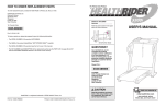
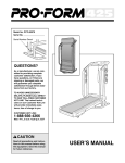
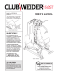
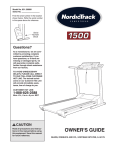
Model No. NTEL11990
Serial No.
USERÕS MANUAL
Serial Number Decal
QUESTIONS?
As a manufacturer, we are committed to providing complete
customer satisfaction. If you
have questions, or if there are
missing parts, we will guarantee
complete satisfaction through
direct assistance from our factory.
TO AVOID UNNECESSARY
DELAYS, PLEASE CALL DIRECT
TO OUR TOLL-FREE CUSTOMER
HOT LINE. The trained technicians on our customer hot line
will provide immediate assistance, free of charge to you.
CUSTOMER HOT LINE:
1-888-825-2588
Mon.ÐFri., 6 a.m.Ð6 p.m. MST
CAUTION
Read all precautions and instructions in this manual before using
this equipment. Keep this manual
for future reference.
Visit our website at
www.nordictrack.com
new products, prizes,
fitness tips, and much more!
TABLE OF CONTENTS
IMPORTANT PRECAUTIONS . . . . . . . . . . . . . . . . . . . . . . . . . . . . . . . . . . . . . . . . . . . . . . . . . . . . . . . . . . . . .3
BEFORE YOU BEGIN . . . . . . . . . . . . . . . . . . . . . . . . . . . . . . . . . . . . . . . . . . . . . . . . . . . . . . . . . . . . . . . . . . .4
ASSEMBLY . . . . . . . . . . . . . . . . . . . . . . . . . . . . . . . . . . . . . . . . . . . . . . . . . . . . . . . . . . . . . . . . . . . . . . . . . . .5
HOW TO USE THE ELLIPTICAL CROSSTRAINER . . . . . . . . . . . . . . . . . . . . . . . . . . . . . . . . . . . . . . . . . . . . .9
MAINTENANCE . . . . . . . . . . . . . . . . . . . . . . . . . . . . . . . . . . . . . . . . . . . . . . . . . . . . . . . . . . . . . . . . . . . . . . .19
CONDITIONING GUIDELINES . . . . . . . . . . . . . . . . . . . . . . . . . . . . . . . . . . . . . . . . . . . . . . . . . . . . . . . . . . . .20
PART LIST . . . . . . . . . . . . . . . . . . . . . . . . . . . . . . . . . . . . . . . . . . . . . . . . . . . . . . . . . . . . . . . . . . . . . . . . . . .22
EXPLODED DRAWING . . . . . . . . . . . . . . . . . . . . . . . . . . . . . . . . . . . . . . . . . . . . . . . . . . . . . . . . . . . . . . . . .23
HOW TO ORDER REPLACEMENT PARTS . . . . . . . . . . . . . . . . . . . . . . . . . . . . . . . . . . . . . . . . . . .Back Cover
LIMITED WARRANTY . . . . . . . . . . . . . . . . . . . . . . . . . . . . . . . . . . . . . . . . . . . . . . . . . . . . . . . . . . .Back Cover
NordicTrack¨ is a registered trademark of ICON Health & Fitness, Inc.
2
IMPORTANT PRECAUTIONS
WARNING:
To reduce the risk of serious injury, read the following important precautions before using the elliptical crosstrainer.
1. Read all instructions in this manual before
using the elliptical crosstrainer.
10. When you stop exercising, allow the pedals
to slowly come to a stop.
2. It is the responsibility of the owner to ensure
that all users of the elliptical crosstrainer
are adequately informed of all precautions.
11. Keep your back straight when using the elliptical crosstrainer; do not arch your back.
12. If you feel pain or dizziness at any time
while exercising, stop immediately and
begin cooling down.
3. Place the elliptical crosstrainer on a level
surface, with a mat beneath it to protect the
floor or carpet. Keep the elliptical crosstrainer indoors, away from moisture and dust.
13. The elliptical crosstrainer is intended for
in-home use only. Do not use the elliptical
crosstrainer in a commercial, rental, or institutional setting.
4. Inspect and tighten all parts regularly.
Replace any worn parts immediately.
5. Keep children under the age of 12 and pets
away from the elliptical crosstrainer at all
times.
14. The decal shown below has been placed on
the elliptical crosstrainer. If the decal is
missing or illegible, please call our Customer
Service Department toll-free at 1-888-8252588 to order a free replacement decal.
Apply the decal in the location shown.
6. The elliptical crosstrainer should not be used
by persons weighing more than 250 pounds.
7. Always hold the handlebar or the pulse handlebar when mounting, dismounting, or
using the elliptical crosstrainer.
8. Wear appropriate exercise clothing when
using the elliptical crosstrainer. Always wear
athletic shoes for foot protection.
9. The pulse sensor is not a medical device.
Various factors may affect the accuracy of
heart rate readings. The pulse sensor is
intended only as an exercise aid in determining heart rate trends in general.
WARNING:
Before beginning this or any exercise program, consult your physician.
This is especially important for persons over the age of 35 or persons with pre-existing health problems. Read all instructions before using. ICON assumes no responsibility for personal injury or
property damage sustained by or through the use of this product.
3
BEFORE YOU BEGIN
Congratulations for selecting the new NordicTrack¨
VGR970 elliptical crosstrainer. The NordicTrack¨
VGR970 is an incredibly smooth exerciser that moves
your feet in a natural elliptical path, minimizing the
impact on your knees and ankles. And the unique
NordicTrack¨ VGR970 features adjustable resistance
and incline to help you get the most from your exercise.
Welcome to a whole new world of natural, ellipticalmotion exercise from NordicTrack.
tional questions, please call our Customer Service
Department toll-free at 1-888-825-2588, Monday
through Friday, 6 a.m. until 6 p.m. Mountain Time
(excluding holidays). To help us assist you, please
note the product model number and serial number
before calling. The model number is NTEL11990. The
serial number can be found on a decal attached to the
elliptical crosstrainer (see the front cover of this manual for the location of the decal).
For your benefit, read this manual carefully before
you use the NordicTrack¨ VGR970. If you have addi-
Before reading further, please familiarize yourself with
the parts that are labeled in the drawing below.
Console
Water Bottle Holder*
Book Rack
Handlebar
Pulse Handlebar
FRONT
Incline Ramp
Pedal Arm
Pedal
BACK
Pedal Disk
RIGHT SIDE
Wheel
*No water bottle is included
4
ASSEMBLY
Assembly requires two people. Place all parts of the elliptical crosstrainer in a cleared area and remove the
packing materials. Do not dispose of the packing materials until assembly is completed. In addition to the
included allen wrenches, assembly requires a phillips screwdriver
, an adjustable
wrench
, and a rubber mallet
.
As you assemble the elliptical crosstrainer, use the drawings below to identify the small parts used in assembly.
The number in parenthesis below each drawing refers to the key number of the part, from the PART LIST on
page 22. The second number refers to the quantity used in assembly. Note: Some small parts may have been
pre-assembled for shipping. If a part is not in the parts bag, check to see if it has been pre-assembled.
M8 Split
Washer (58)Ð4
M8 Washer (33)Ð4
Incline Axle
Screw (30)Ð4
Console
Washer (44)Ð4
M10 Flat
Washer (89)Ð1
Console Screw (35)Ð4
M10 x 24mm Screw (90)Ð1
Rear Stabilizer Bolt (60)Ð2
Pedal Screw (43)Ð6
Front Stabilizer Bolt (86)Ð2
56mm Spacer (22)Ð2
3/4Ó Axle Cap (61)Ð2
Plastic Pedal
Spacer (85)Ð2
5
M10 Nylon
Locknut (26)Ð4
1. Identify the Rear Stabilizer (59), which has Wheels (45)
attached to it.
1
59
26
Attach the Rear Stabilizer (59) to the rear of the Frame
(1) with the two Rear Stabilizer Bolts (60) and two M10
Nylon Locknuts (26). Make sure that the Rear
Stabilizer is turned so the Wheels are not touching
the floor.
26
45
1
60
2. Attach the Front Stabilizer (14) to the front of the
Frame (1) with the two Front Stabilizer Bolts (86) and
two M10 Nylon Locknuts (26).
2
14
86
26
1
3. Slide an M8 Split Washer (58) and an M8 Washer (33)
onto an Incline Axle Screw (30). Tighten the Incline
Axle Screw into one end of an Incline Axle (29). Next,
apply a small amount of the included grease to the
Incline Axle.
26
3
V-shaped Groove
5
Align the indicated tubes on the Incline Ramp (5) with
the tubes on the Base (1). Make sure that the Incline
Ramp is turned so the V-shaped grooves are on
top. Insert the Incline Axle (29) through the Incline
Ramp and the Base. Note: It may be helpful to tap the
Incline Axle with a rubber mallet to insert it.
58
33
30
Grease
Slide an M8 Split Washer (58) and an M8 Washer (33)
onto another Incline Axle Screw (30). Tighten the
Incline Axle Screw into the open end of the Incline Axle
(29).
58
29
Tubes
33
1
30
Tubes
4. Slide an M8 Split Washer (58) and an M8 Washer (33)
onto an Incline Axle Screw (30). Tighten the Incline Axle
Screw into one end of the other Incline Axle (29). Next,
apply a small amount of grease to the Incline Axle.
Raise the Incline Ramp (5). Insert the Incline Axle (29)
through one side of the Incline Ramp, through a 56mm
Spacer (22), through the end of the motor screw,
through another 56mm Spacer (22), and then through
the other side of the Incline Ramp.
Slide an M8 Split Washer (58) and an M8 Washer (33)
onto another Incline Axle Screw (30). Tighten the Incline
Axle Screw into the open end of the Incline Axle (29).
6
4
58
22
30
Motor
Screw
29
33
58
Grease
30
33
5
5. Identify the Left Pedal Arm (3), which has an ÒLÓ sticker
attached to it. Next, identify the Left Pedal (41), which
has the letter ÒLÓ molded onto the bottom.
5
43
Turn over the Left Pedal Arm (3) as shown. Insert the
three plastic posts on the Left Pedal (41) into the three
indicated holes in the Left Pedal Arm. Make sure that
the Left Pedal is turned as shown. Attach the Left
Pedal with three Pedal Screws (43).
3
Attach the Right Pedal (not shown) to the Right Pedal
Arm (not shown) in the same way.
Open Side
Plastic Posts
41
6. Apply a small amount of grease to the axle on the left
Crank Arm (6).
6
Side a Plastic Pedal Spacer (85) and the Left Pedal
Arm (3) onto the axle on the left Crank Arm (6). Note: It
may be helpful to use a rubber mallet to tap these parts
on. Be careful not to confuse the Left Pedal Arm
with the Right Pedal Arm (not shown); look at the
position of the round tube to correctly identify the
Left Pedal Arm. Next, tap a 3/4Ó Axle Cap (61) onto
the axle.
Grease
3
6
85
Attach the Right Pedal Arm (not shown) in the same way.
61
7. Carefully pivot the Upright (2) to the position shown.
Secure the Upright by tightening the M10 x 24mm
Screw (90) with the M10 Flat Washer (89) into the
Upright and the Frame (1).
Round
Tube
7
2
90
89
1
7
8. This step requires the help of a second person.
8
87
Remove the four Console Screws (35) and the four
Console Washers (44) from the Console (87).
Hold the Console (87) in the position shown and
connect the console wire harness to the Upper Wire
Harness (51). Remove the rubber band from the Upper
Wire Harness and push the Upper Wire Harness and
the console wire harness down into the Upright (2). Set
the Console on the Upright. Make sure that the console wire harness is not pinched between the
Console and the Upright.
Hold the Handlebar (18) in the position shown. Align
the four holes in the Handlebar with the four holes in
the plate at the top of the Upright (2). Attach the
Handlebar and the Console (87) to the Upright with the
four Console Screws (35) and the four Console
Washers (44) that you removed previously. Note:
Thread all four Console Screws into the Console
before tightening them.
Console
Wire
Harness
51
18
2
44
35
35
9. Make sure that all parts of the elliptical crosstrainer are properly tightened. Note: Some hardware
may be left over after assembly is completed. To protect the floor or carpet from damage, place a mat
under the elliptical crosstrainer.
8
HOW TO USE THE ELLIPTICAL CROSSTRAINER
HOW TO PLUG IN THE POWER CORD
EXERCISING ON THE ELLIPTICAL CROSSTRAINER
Locate the power cord on the elliptical crosstrainer.
Plug the power cord into an electrical outlet.
To mount the elliptical crosstrainer, hold the handlebar
and step onto the pedal that is in the lowest position.
Next, step onto the other pedal. Push the pedals until
they begin to move with a continuous motion.
Note: Each time the
power cord is plugged
in, the resistance system will automatically
calibrate itself.
Calibration will take
less than one minute.
During calibration, the
letters ÒCALÓ will
appear in the left LED display and the indicators in
the TRAINING ZONE display will light in a rapid
sequence.
Handlebar
Pedals
After the resistance
system calibrates
itself, the incline system may calibrate
itself. During calibration, two dashes will
appear in the center
LED display and the
indicators in the
TRAINING ZONE display will light in a rapid
sequence.
Pedal Disk
Note: The pedal disks can turn in either direction.
It is recommended that you move the pedal disks
in the direction shown by the arrow above; however, to give variety to your exercise, you may
turn the pedal disks in the opposite direction.
To dismount the elliptical crosstrainer, wait until the
pedals come to a complete stop. Note: The elliptical
crosstrainer does not have a freewheel; the pedals will continue to move until the flywheel stops.
When the pedals are stationary, step off the highest
pedal first. Then, step off the lowest pedal.
9
DESCRIPTION OF THE CONSOLE
HOW TO USE THE MANUAL MODE
1
Make sure that the power cord is plugged in.
Refer to page 9.
2
Press any button on the console or move the
pedals to turn on the power.
When one of the buttons on the console is
pressed or the pedals are moved, various displays
and indicators will light and the left LED display
will begin to flash. Note: If the power cord was
just plugged in, the power will already be on.
3
Select the manual mode.
When the power is
turned on, the
manual mode will
be selected and
Manual
the manual indicaIndicator
tor will light. If you
have selected a
program or the iFit.com mode, press the SELECT
WORKOUT button repeatedly until the manual
indicator lights.
The advanced console offers a variety of features to
help you get the most from your workouts.
4
When the manual mode of the console is selected, the
angle of the ramp and the resistance of the pedals can
be changed with a touch of a button. As you exercise,
the program display, the training zone display, and the
three LED displays will provide continuous exercise
feedback. You can even measure your heart rate using
the built-in pulse sensor.
Begin exercising and adjust the resistance of
the pedals as desired.
As you exercise,
change the resistance of the pedals
by pressing the
RESISTANCE buttons. There are ten
resistance levels;
level 1 is the easiest. Note: After a RESISTANCE
button is pressed, it will take a moment for the
pedals to reach the selected resistance level.
In addition, the console offers five preset workout programs. Each program automatically changes the ramp
angle and the resistance of the pedals as it guides you
through an effective workout. You can even create
your own workout programs and store them in memory
for future use.
5
Adjust the angle of the ramp as desired.
To vary your exercise, change the
angle of the ramp
by pressing the
RAMP ANGLE buttons. There are
five angles that
simulate skiing, walking, cycling, and climbing.
Note: After a RAMP ANGLE button is pressed, it
will take a moment for the ramp to reach the
selected angle.
The console also features revolutionary iFit.com technology. IFit.com technology allows the console to play
specially-designed CD's (available separately) that
automatically control the ramp angle and the resistance of the pedals as a personal trainer coaches you
through every step of your workout. High-energy
music provides added motivation. Each CD features
two workout programs designed by AFAª-certified
personal trainers.
For information about iFit.com CDÕs, call toll-free
1-800-735-0768 or visit our Web site at www.iFit.com.
10
6
The right LED displayÑAs you exercise, the right display will show the
approximate number of calories you
have burned. This
display will also show your heart rate when the
pulse sensor is used (see step 7).
Watch your progress with the program display,
the training zone display, and the LED displays.
The program
displayÑWhen
the manual mode
or the iFit.com
mode is selected,
the program display will show a
track representing 1/4 mile. As you exercise, the
indicators around the track will light in sequence
until the entire track is lit. A new lap will then begin.
7
Measure your heart rate, if desired.
Note: If the metal contacts on the top and bottom of the pulse sensor are covered with
clear vinyl strips, peel off the strips before
using the pulse sensor.
The training zone
displayÑAs you
exercise, the training zone display
will show the
approximate intensity level of your
exercise. For example, if four, five, or six indicators
in the display are lit (refer to the drawing above),
the display shows that your intensity level is ideal
for fat burning.
To measure
your heart rate,
place your
hands on the
metal contacts
on the pulse
Metal
sensor. Your
Contacts
palms must be
resting on the
upper contacts and your fingers must be touching
the lower contacts. Avoid moving your hands.
The left LED displayÑAs you
exercise, the left
display will show
the elapsed time
and the current
resistance level.
The display will change from one number to the
other every six seconds, as shown by the indicators around the display. Note: When a program is
selected, the left display will show the time
remaining in the program, the time remaining in
the current segment of the program, and the current resistance level.
When your pulse is detected, the heart rate indicator above the right LED display will light, one to
three dashes will appear in the display, and then
your heart rate will be shown. For the most accurate heart rate reading, continue to hold the contacts for about 15 seconds. Note: If your heart rate
is not shown, make sure that your hands are
positioned as described above. Be careful not to
move your hands excessively or squeeze the
metal contacts too tightly.
Note: When you use the pulse sensor, the right
display will show your heart rate for up to two
minutes. If you continue to hold the pulse sensor,
the display will show your heart rate along with
the number of calories you have burned.
Note: If you stop exercising for six seconds or
longer, the console will pause and the left LED
display will begin to flash.
The center LED
displayÑAs you
exercise, the center display will
show your current
speed, the ramp
angle, and the distance you have traveled. The display will change
from one number to the next every six seconds,
as shown by the indicators around the display.
8
When you are finished exercising, turn off the
power.
To turn off the power, simply wait for about ten
minutes. The console has an Òauto-offÓ feature.
If the console buttons are not pressed and the
pedals are not moved for ten minutes, the
console will turn off automatically.
Note: If the displays and indicators remain lit
after ten minutes, the console may be in the
ÒdemoÓ mode. Refer to the instructions on
page 18 to turn off the demo mode.
Note: Speed and distance can be shown in
either miles or kilometers. To select the
desired unit of measurement, refer to page 18.
11
settings for the next
Current Segment
ten segments will
be shown in the ten
columns to the
right. (The ramp
angle settings are
not shown in the
program display.)
When only three seconds remain in the first segment of the program, both the Current Segment
column and the column to the right will flash, a
series of tones will sound, and all resistance settings will move one column to the left. The resistance setting for the second segment will then be
shown in the flashing Current Segment column
and the resistance of the pedals and the angle of
the ramp will automatically adjust to the second
settings. The program will continue in this way
until the resistance setting for the last segment is
shown in the Current Segment column and the
last segment ends.
HOW TO USE PRESET PROGRAMS
1
Make sure that the power cord is plugged in.
Refer to page 9.
2
Press any button on the console or move the
pedals to turn on the power.
Refer to step 2 on page 10.
3
Select one of the five preset programs.
When the power is
Preset Program Indicator
turned on, the
manual mode will
be selected and
the manual indicator will light. To
select a preset
program, press
the SELECT WORKOUT button repeatedly until
one of the five preset program indicators lights.
Note: Each time a segment ends and the resistance settings move to the left, if all of the indicators in the Current Segment column are lit, the
resistance settings may move downward so that
only the highest indicators in the columns will be
shown in the program display. When the resistance
settings move to the left again and not all of the
indicators in the Current Segment column are lit,
the resistance settings will move back up.
The graphs below show how the resistance will
change during the five preset programs. (The
ramp angle will also change during the programs;
however, the ramp angle settings are not shown
on the graphs.) Note: When a program is selected, the program display will show a simplified
graph of the program.
Note: You can manually override the resistance
setting or the ramp angle setting for the current
segment, if desired, by pressing the RESISTANCE or RAMP ANGLE buttons. However,
when the next segment of the program
begins, the resistance of the pedals and the
angle of the ramp will automatically adjust to
the settings for the next segment.
Note: If you stop exercising for six seconds or
longer, the program will pause and the left LED
display will begin to flash. To restart the program,
simply resume exercising.
5
4
Press the START PROGRAM button and begin
exercising.
Watch your progress with the training zone
display and the LED displays.
Refer to step 6 on page 11.
6
Each program is divided into several individual
segments. Each segment is one, two, three, or
four minutes long. One resistance setting and one
ramp angle setting are programmed for each segment. The resistance setting for the first segment
will be shown in the flashing Current Segment
column of the program display. The resistance
Measure your heart rate, if desired.
Refer to step 7 on page 11.
7
When the program is finished, turn off the
power.
Refer to step 8 on page 11.
12
the desired resistance and ramp angle settings
for the first segment, simply adjust the resistance
of the pedals and the angle of the ramp as
desired with the RESISTANCE and RAMP
ANGLE buttons. As the resistance setting is
increased, additional indicators will light in the
Current Segment column of the program display.
Note: While you are creating a custom program,
the program display will show a maximum of five
lit indicators, even if you program a higher resistance setting.
HOW TO CREATE A CUSTOM PROGRAM
1
Make sure that the power cord is plugged in.
Refer to page 9.
2
Press any button on the console or move the
pedals to turn on the power.
Refer to step 2 on page 10.
3
When the first segment of the program is completed, the current resistance setting and the current ramp angle setting will be stored in memory.
All columns in the program display will then move
one column to the left and the resistance setting
for the second segment will be shown in the
flashing Current Segment column. Program resistance and ramp angle settings for the second
segment as described above.
Select one of the custom programs.
When the power is
Custom Program Indicator
turned on, the
manual mode will
be selected and
the manual indicator will light. To
select a custom
program, press
the SELECT WORKOUT button repeatedly until
one of the two custom program indicators lights.
4
5
Repeat this procedure until you have programmed
resistance and ramp angle settings for as many
segments as desiredÑcustom programs can
have up to forty segments.
Press the START PROGRAM button and begin
exercising.
Note: If you stop exercising for six seconds or
longer, the program will pause and the left LED
display will begin to flash. To restart the program,
simply resume exercising.
Press the RECORD button and program the
desired resistance and ramp angle settings.
When the RECORD button is pressed, the indicator beside the button will light. Resistance and
ramp angle settings can be programmed only
when the indicator is lit. Note: When the indicator beside the RECORD button is lit, the left LED
display will show the elapsed time instead of the
time remaining in the program.
6
Press the SELECT WORKOUT button to end
the custom program.
When you have programmed resistance and
ramp angle settings for as many segments as
desired, press the SELECT WORKOUT button.
The resistance and ramp angle settings that you
programmed and the number of completed
segments will be stored in memory. To use the
custom program, see HOW TO USE CUSTOM
PROGRAMS on page 14.
Refer to the program display. Each custom program is divided into one-minute segments. One
resistance setting and one ramp angle setting
can be programmed for each
Current Segment
segment. The
resistance setting
for the first segment will be
shown in the
flashing Current
Segment column
of the program display. (The ramp angle settings
are not shown in the program display.) To program
7
When the program is finished, turn off the
power.
Refer to step 8 on page 11.
13
When only three seconds remain in the first segment of the program, both the Current Segment
column and the column to the right will flash, a
series of tones will sound, and all resistance settings will move one column to the left. The resistance setting for the second segment will then be
shown in the flashing Current Segment column
and the resistance of the pedals and the angle of
the ramp will automatically adjust to the second
settings that you programmed previously.
HOW TO USE CUSTOM PROGRAMS
1
Make sure that the power cord is plugged in.
Refer to page 9.
2
Press any button on the console or move the
pedals to turn on the power.
Refer to step 2 on page 10.
3
The program will continue in this way until the
resistance setting for the last segment is shown
in the Current Segment column and the last segment ends.
Select one of the custom programs.
When the power is
Custom Program Indicator
turned on, the
manual mode will
be selected and
the manual indicator will light. To
select a custom
program, press
the SELECT WORKOUT button repeatedly until
one of the two custom program indicators lights.
Note: If the program is too easy or too difficult,
the resistance or ramp angle setting for the current
segment can be adjusted with the RESISTANCE
or RAMP ANGLE buttons. Adjustments will not be
stored in memory. To reprogram the resistance or
ramp angle setting for the current segment, press
the RECORD button. The indicator beside the button will light. Resistance and ramp angle settings
can be programmed only when the indicator is
lit. Adjust the resistance or ramp angle setting for
the current segment with the RESISTANCE or
RAMP ANGLE buttons. After the segment is completed, press the RECORD button again. The new
setting will be stored in memory.
Note: When a custom program is selected, the
program display will show a simplified graph of
the program.
4
Press the START PROGRAM button and begin
exercising.
Note: If you stop exercising for six seconds or
longer, the program will pause and the left LED
display will begin to flash. To restart the program,
simply resume exercising.
When the program is started, the resistance of
the pedals and the angle of the ramp will adjust
to the first settings that you programmed previously.
5
Each program is divided into several individual
segments. One resistance setting and one ramp
angle setting are programmed for each segment.
The resistance
setting for the first
Current Segment
segment will be
shown in the
flashing Current
Segment column
of the program
display. The resistance settings for
the next ten segments will be shown in the ten
columns to the right. (The ramp angle settings
are not shown in the program display.)
Watch your progress with the training zone
display and the LED displays.
Refer to step 6 on page 11.
6
Measure your heart rate, if desired.
Refer to step 7 on page 11.
7
When the program is finished, turn off the
power.
Refer to step 8 on page 11.
14
HOW TO CONNECT YOUR PORTABLE STEREO
HOW TO CONNECT YOUR CD PLAYER TO THE
ELLIPTICAL CROSSTRAINER
Note: If your stereo has an RCA-type AUDIO OUT
jack, see instruction A below. If your stereo has a
3.5mm LINE OUT jack, see instruction B. If your
stereo has only a PHONES jack, see instruction C.
To use iFit.com CDÕs (available separately), the elliptical crosstrainer must be connected to your portable
CD player, portable stereo, home stereo, or computer
with CD player. Refer to this page and page 16 for
connecting instructions.
A. Plug one end of the audio cable into the jack
beneath the console of the elliptical crosstrainer.
Plug the other end of the cable into the included
adapter. Plug the adapter into an AUDIO OUT jack
on your stereo.
HOW TO CONNECT YOUR PORTABLE CD PLAYER
Note: If your CD player has separate LINE OUT
and PHONES jacks, see instruction A below. If
your CD player has only one jack, see instruction
B.
A/B
AUDIO OUT
RIGHT
A. Plug one end of the audio cable into the jack
beneath the console of the elliptical crosstrainer.
Plug the other end of the cable into the LINE OUT
jack on your CD player. Plug your headphones into
the PHONES jack.
LEFT
Adapter
Audio Cable
A
PHONES LINE OUT
LINE OUT
B. Plug one end of the audio cable into the jack
beneath the console of the elliptical crosstrainer.
Plug the other end of the cable into the LINE OUT
jack on your stereo. Do not use the adapter.
PHONES
Headphones
Audio
Cable
C. Plug one end of the audio cable into the jack
beneath the console of the elliptical crosstrainer.
Plug the other end of the cable into a 3.5mm Yadapter (available at electronics stores). Plug the Yadapter into the PHONES jack on your stereo. Plug
your headphones into the other side of the Yadapter.
B. Plug one end of the audio cable into the jack
beneath the console of the elliptical crosstrainer.
Plug the other end of the cable into a 3.5mm Yadapter (available at electronics stores). Plug the Yadapter into the PHONES jack on your CD player.
Plug your headphones into the other side of the Yadapter.
C
PHONES
B
3.5mm
Audio
Y-adapter
Cable
PHONES
PHONES
Audio
Cable
3.5mm
Y-adapter
Headphones
Headphones
15
HOW TO CONNECT YOUR HOME STEREO
HOW TO CONNECT YOUR COMPUTER
Note: If your stereo has an unused LINE OUT jack,
see instruction A below. If the LINE OUT jack is
being used, see instruction B.
Note: If your computer has a 3.5mm LINE OUT
jack, see instruction A. If your computer has only a
PHONES jack, see instruction B.
A. Plug one end of the audio cable into the jack
beneath the console of the elliptical crosstrainer.
Plug the other end of the cable into the included
adapter. Plug the adapter into the LINE OUT jack
on your stereo.
A. Plug one end of the audio cable into the jack
beneath the console of the elliptical crosstrainer.
Plug the other end of the cable into the LINE OUT
jack on your computer.
A
A
CD
LINE OUT
VCR
Amp
LINE OUT
Audio
Cable
LINE OUT
Adapter
Audio Cable
B. Plug one end of the audio cable into the jack
beneath the console of the elliptical crosstrainer.
Plug the other end of the cable into a 3.5mm Yadapter (available at electronics stores). Plug the Yadapter into the PHONES jack on your computer.
Plug your headphones or speakers into the other
side of the Y-adapter.
B. Plug one end of the audio cable into the jack
beneath the console of the elliptical crosstrainer.
Plug the other end of the cable into the included
adapter. Plug the adapter into an RCA Y-adapter
(available at electronics stores). Next, remove the
wire that is currently plugged into the LINE OUT
jack on your stereo and plug the wire into the
unused side of the RCA Y-adapter. Plug the RCA
Y-adapter into the LINE OUT jack on your stereo.
B
B
PHONES
CD
VCR
Amp
Audio Cable
3.5mm
Y-adapter
LINE OUT
Headphones/Speakers
Audio
Cable
RCA
Y-adapter
Adapter
Wire removed from
LINE OUT jack
16
During the CD program, the resistance of the
pedals and the angle of the ramp will automatically
change according to the settings of the program.
An electronic ÒchirpingÓ sound will alert you when
the resistance and/or ramp angle is about to
change. If the resistance or ramp angle setting is
too high or too low, you can manually override
the setting at any time by pressing the RESISTANCE or RAMP ANGLE buttons on the console.
However, when the next ÒchirpÓ is heard, the
resistance and/or ramp angle will change to the
next setting for the program.
HOW TO USE IFIT.COM CDÕS
IFit.com CDÕs (available separately) automatically control the resistance of the pedals as a personal trainer
coaches you through every step of your workout. For
information about purchasing CDÕs, call toll-free 1-800999-3756.
Before using iFit.com CDÕs, you must connect the
elliptical crosstrainer to your CD player. Refer to
pages 15 and 16 for connecting instructions. Follow
the steps below to use iFit.com CDÕs.
1
Note: If the resistance of the pedals and/or the
angle of the ramp does not change when a
ÒchirpÓ is heard:
Make sure that the power cord is plugged in.
Refer to page 9.
2
¥ make sure that the indicator on the IFIT.COM
button is lit
Press any button on the console or move the
pedals to turn on the power.
¥ adjust the volume of your CD player. If the
volume is too high or too low, the console
may not detect the program signals
Refer to step 2 on page 10.
3
¥ make sure that the audio cable is properly
connected and that it is fully plugged in.
Select the iFit.com mode.
When the power
is turned on, the
manual mode will
be selected and
the manual indicator will light. To
select the
iFit.com mode, press the IFIT.COM button. The
indicator beside the button will light.
4
Insert the iFit.com CD into your CD player.
5
Press the play button on your CD player to
start the program.
6
Watch your progress with the program display,
the training zone display, and the LED displays.
Refer to step 6 on page 11.
7
Measure your heart rate, if desired.
Refer to step 7 on page 11.
8
When the program is finished, turn off the
power.
Refer to step 8 on page 11.
A moment after the play button is pressed, your
personal trainer will begin guiding you through
your workout. Simply follow your personal trainerÕs
instructions.
17
The right LED display
will show an ÒEÓ for
English miles or an ÒMÓ
for metric kilometers.
Press the START PROGRAM button to change
the unit of measurement, if desired.
THE INFORMATION MODE/DEMO MODE
The console features an information mode that keeps
track of the total number of hours that the elliptical
crosstrainer has been used and the total number of
miles that the pedals have moved. The information
mode also allows you to switch the console from miles
to kilometers. In addition, the information mode allows
you to turn on and turn off the demo mode.
IMPORTANT: Make
sure that there is not
a ÒdÓ in the right display. If a ÒdÓ appears in
the display, the console
is in the ÒdemoÓ mode.
This mode is intended to
be used only when an elliptical crosstrainer is displayed
in a store. When the console is in the demo mode, the
power cord can be plugged in and the displays and
indicators on the console will automatically light in a
preset sequence, although the buttons on the console
will not operate. If a ÒdÓ appears in the right display
when the information mode is selected, press the
SELECT WORKOUT button so the ÒdÓ disappears.
To select the information mode, press RESISTANCE
button Ò1Ó and the SELECT WORKOUT button at the
same time. The following information will be shown:
The left LED display
will show the total number of hours that the
elliptical crosstrainer
has been used.
The center LED display
will show the total number of miles that the
pedals have moved.
To exit the information mode, press RESISTANCE button Ò1Ó and the SELECT WORKOUT button at the
same time.
18
MAINTENANCE
For smooth
operation of
the elliptical
crosstrainer,
the incline
ramp should be
kept clean.
Using a soft
cloth and mild
detergent,
clean dust and
other residue
from the incline ramp where the wheels make contact
with it. Other parts of the elliptical crosstrainer can
also be cleaned in this manner. Never use abrasives
or solvents.
Incline
Ramp
Inspect and tighten all parts of the elliptical crosstrainer
regularly. Replace any worn parts immediately.
Wheel
19
CONDITIONING GUIDELINES
The following guidelines will help you to plan your
exercise program. Remember that proper nutrition
and adequate rest are essential for successful results.
Fat Burning
To burn fat effectively, you must exercise at a relatively low intensity level for a sustained period of time.
During the first few minutes of exercise, your body
uses easily accessible carbohydrate calories for energy. Only after the first few minutes of exercise does
your body begin to use stored fat calories for energy.
If your goal is to burn fat, adjust the intensity of your
exercise until your heart rate is near the lowest number in your training zone as you exercise.
WARNING:
Before beginning this or any exercise program, consult your physician. This is especially important for persons over the age of 35
or persons with pre-existing health problems.
The pulse sensor is not a medical device.
Various factors may affect the accuracy of
heart rate readings. The pulse sensor is
intended only as an exercise aid in determining heart rate trends in general.
For maximum fat burning, adjust the intensity of your
exercise until your heart rate is near the middle number in your training zone as you exercise.
Aerobic Exercise
If your goal is to strengthen your cardiovascular system, your exercise must be Òaerobic.Ó Aerobic exercise is activity that requires large amounts of oxygen
for prolonged periods of time. This increases the
demand on the heart to pump blood to the muscles,
and on the lungs to oxygenate the blood. For aerobic
exercise, adjust the intensity of your exercise until
your heart rate is near the highest number in your
training zone.
EXERCISE INTENSITY
Whether your goal is to burn fat or to strengthen your
cardiovascular system, the key to achieving the
desired results is to exercise with the proper intensity.
The proper intensity level can be found by using your
heart rate as a guide. The chart below shows recommended heart rates for fat burning, maximum fat
burning, and cardiovascular (aerobic) exercise.
WORKOUT GUIDELINES
Each workout should include the following three
important parts:
A warm-up, consisting of 5 to 10 minutes of stretching
and light exercise (see SUGGESTED STRETCHES
on page 21). A proper warm-up increases your body
temperature, heart rate, and circulation in preparation
for exercise.
Training zone exercise, consisting of 20 to 30 minutes of exercising with your heart rate in your training
zone. (During the first few weeks of your exercise
program, do not keep your heart rate in your training
zone for longer than 20 minutes.)
To find the proper heart rate for you, first find your age
on the bottom line of the chart (ages are rounded off
to the nearest ten years). Next, find the three numbers
above your age. The three numbers are your Òtraining
zone.Ó The lowest number is the recommended heart
rate for fat burning; the middle number is the recommended heart rate for maximum fat burning; the highest number is the recommended heart rate for aerobic
exercise.
A cool-down, with 5 to 10 minutes of stretching. This
will increase the flexibility of your muscles and will
help to prevent post-exercise problems.
To maintain or improve your condition, complete three
workouts each week, with at least one day of rest
between workouts. After a few months of regular exercise, you may complete up to five workouts each week
if desired. The key to success is to make exercise a
regular and enjoyable part of your everyday life.
To measure your heart rate, first exercise for at least
four minutes. Then, measure your heart rate using the
pulse sensor (see step 7 on page 11).
20
SUGGESTED STRETCHES
The correct form for several basic stretches is shown below. Move slowly as you stretchÑnever bounce.
1. Toe Touch Stretch
1
Stand with your knees bent slightly and slowly bend forward from
your hips. Allow your back and shoulders to relax as you reach
down toward your toes as far as possible. Hold for 15 counts, then
relax. Repeat 3 times. Stretches: Hamstrings, back of knees and
back.
2. Hamstring Stretch
2
Sit with one leg extended. Bring the sole of the opposite foot toward
you and rest it against the inner thigh of your extended leg. Reach
toward your toes as far as possible. Hold for 15 counts, then relax.
Repeat 3 times for each leg. Stretches: Hamstrings, lower back and
groin.
3. Calf/Achilles Stretch
With one leg in front of the other, reach forward and place your
hands against a wall. Keep your back leg straight and your back
foot flat on the floor. Bend your front leg, lean forward and move
your hips toward the wall. Hold for 15 counts, then relax. Repeat 3
times for each leg. To cause further stretching of the achilles tendons, bend your back leg as well. Stretches: Calves, achilles tendons and ankles.
3
4
4. Quadriceps Stretch
With one hand against a wall for balance, reach back and grasp
one foot with your other hand. Bring your heel as close to your buttocks as possible. Hold for 15 counts, then relax. Repeat 3 times for
each leg. Stretches: Quadriceps and hip muscles.
5. Inner Thigh Stretch
5
Sit with the soles of your feet together and your knees outward. Pull
your feet toward your groin area as far as possible. Hold for 15
counts, then relax. Repeat 3 times. Stretches: Quadriceps and hip
muscles.
21
PART LISTÑModel No. NTEL11990
Key No. Qty.
1
2
3
4
5
6
7
8
9
10
11
12
13
14
15
16
17
18
19
20
21
22
23
24
25
26
27
28
29
30
31
32
33
34
35
36
37
38
39
40
41
42
43
44
45
46
47
48
49
50
51
52
1
1
1
1
1
2
1
1
2
1
1
1
4
1
2
1
2
1
1
2
1
2
1
1
1
13
1
1
2
6
6
4
6
1
4
1
1
2
1
2
1
1
6
4
2
2
1
1
1
1
1
1
Description
R0100A
Key No. Qty.
Frame
Upright
Left Pedal Arm
Right Pedal Arm
Incline Ramp
Crank Arm
Power Cord
Large Pulley
Frame Bearing
Plastic Crank Spacer
Flat Delrin Washer
Idler Bracket
Nut
Front Stabilizer
Upright Endcap
Idler Arm Screw
M10 Flat Washer
Handlebar
Arm Axle
Handlebar Endcap
Incline Motor
56mm Spacer
Incline Reed Switch
Side Shield Support
Wire Harness
M10 Nylon Locknut
Reed Switch Lock
Belt
Incline Axle
Incline Axle Screw
Incline Bushing
Incline Ramp Cap
M8 Washer
Upright Axle
Console Screw
Spring
Flywheel
Flywheel Bearing
Flywheel Axle
Pedal Disk
Left Pedal
Right Pedal
Pedal Screw
Console Washer
Wheel
Wheel Bolt
Left Side Shield
Right Side Shield
Console Base
Reed Switch/Wire
Upper Wire Harness
Reed Switch Bracket
53
54
55
56
57
58
59
60
61
62
63
64
65
66
67
68
69
70
71
72
73
74
75
76
77
78
79
80
81
82
83
84
85
86
87
88
89
90
91
92
93
94
95
96
97
98
99
100
101
#
#
#
1
1
1
1
1
6
1
2
2
2
4
2
1
1
2
1
1
1
1
10
8
1
1
4
2
1
2
3
4
4
2
1
2
2
1
4
1
1
1
2
2
1
4
2
5
1
1
1
1
1
2
1
Description
Resistance Cable
Reed Switch Clamp
Magnet
ÒCÓ Magnet
Stop Bolt
M8 Split Washer
Rear Stabilizer
Rear Stabilizer Bolt
3/4Ó Axle Cap
Front Stabilizer Endcap
Pedal Arm Cap
Rear Stabilizer Endcap
ÒJÓ Bolt Nut
ÒJÓ Bolt
M10 Nylon Jam Nut
Eyebolt
M6 Nylon Locknut
Adjustment Bracket
M4 x 63.5mm Screw
M4 x 16mm Screw
M5 x 16mm Screw
Frame Endcap
Left Incline Side Shield
Pedal Bushing
Pedal Wheel
Right Incline Side Shield
Pedal Wheel Bolt
M8 Nylon Locknut
M8 Black Washer
Wheel Spacer
Flange Bolt
Grommet
Plastic Pedal Spacer
Front Stabilizer Bolt
Console
M5 x 25mm Screw
M10 Flat Washer
M10 x 24mm Screw
Incline Bolt
Incline Washer
Incline Spacer
Incline Nut
Tree Fastener
Incline Side Shield Screw
#8 x 1Ó Screw
Junction Box/Cover
Wiring Board
Zip Tie
#8 x 1/2Ó Zip Screw
Grease
Allen Wrench
UserÕs Manual
Note: # indicates a non-illustrated part. Specifications are subject to change without notice.
22
88
32
27
23
58
47
29
30
33
58
33
30
40
22
31
20
72
21
18
75
5
31
22
29
31
32
20
95
51
33
34
96
78
62
43
82
80
2
96
77
81
86
95
30
58
30
33
58
33
63
81
79
82
25
44
35
15
90
91
14
41
30
49
58
33
74
89
93
31
26
3
87
85
6
73
76
76
42
71
81
79
82
17
43
69 70
73
52
80 36
50
72
54
63
37
63
48
55
82
81
80
94 77
92
62
83
31 25
26 17 38
39
67
13
93
12
16
66
65
53
26
92
7
61
4
13 9
57
13
56
73
38
68 67
11
8
1
26
59
64
73
72
24
10
46
73
72
85
6 83
9
98 97
99
40
88
98
63
76 61
26
45
46
97
64
100
28
76
60
101
26 84
26
45
23
R0100A
EXPLODED DRAWINGÑModel No. NTEL11990
HOW TO ORDER REPLACEMENT PARTS
To order replacement parts, simply call our Customer Service Department toll-free at 1-888-825-2588, Monday
through Friday, 6 a.m. until 6 p.m. Mountain Time (excluding holidays). To help us assist you, please be
prepared to give the following information when calling:
¥ The MODEL NUMBER of the product (NTEL11990)
¥ The NAME of the product (NordicTrack¨ VGR970 elliptical crosstrainer)
¥ The SERIAL NUMBER of the product (see the front cover of this manual)
¥ The KEY NUMBER and DESCRIPTION of the part(s) (see page 22 of this manual).
LIMITED WARRANTY
WHAT IS COVEREDÑThe entire NordicTrack¨ VGR970 elliptical crosstrainer (ÒProductÓ) is warranted to be free of all defects in
material and workmanship.
WHO IS COVEREDÑThe original purchaser or any person receiving the Product as a gift from the original purchaser.
HOW LONG IS IT COVEREDÑICON Health & Fitness, Inc. (ÒICONÓ), warrants the product for two years after the date of purchase.
Labor is covered for two years.
WHAT WE DO TO CORRECT COVERED DEFECTSÑWe will ship to you, without charge, any replacement part or component, providing the repairs are authorized by ICON first and are performed by an ICON trained and authorized service provider, or, at our
option, we will replace the Product.
WHAT IS NOT COVEREDÑAny failures or damage caused by unauthorized service, misuse, accident, negligence, improper assembly or installation, alterations, modifications without our written authorization or by failure on your part to use, operate, and maintain
as set out in your UserÕs Manual (ÒManualÓ).
WHAT YOU MUST DOÑAlways retain proof of purchase, such as your bill of sale; store, operate, and maintain the Product as specified in the Manual; notify our Customer Service Department of any defect within 10 days after discovery of the defect; as instructed, return any defected part for replacement or, if necessary, the entire product, for repair.
USERÕS MANUALÑIt is VERY IMPORTANT THAT YOU READ THE MANUAL before operating the Product. Remember to do the
periodic maintenance requirements specified in the Manual to assure proper operation and your continued satisfaction.
HOW TO GET PARTS AND SERVICEÑSimply call our Customer Service Department at 1-888-825-2588 and tell them your name
and address and the serial number of your Product. They will tell you how to get a part replaced, or if necessary, arrange for service
where your Product is located or advise you how to ship the Product for service. Before shipping, always obtain a Return
Authorization Number (RA No.) from our Customer Service Department; securely pack your Product (save the original shipping carton if possible); put the RA No. on the outside of the carton and insure the product. Include a letter explaining the product or problem and a copy of your proof of purchase if you believe the service is covered by warranty.
ICON is not responsible or liable for indirect, special or consequential damages arising out of or in connection with the use or performance of the product or damages with respect to any economic loss, loss of property, loss of revenues or profits, loss of enjoyment or use, costs of removal, installation or other consequential damages of whatsoever nature. Some states do not allow the exclusion or limitation of incidental or consequential damages. Accordingly, the above limitation may not apply to you.
The warranty extended hereunder is in lieu of any and all other warranties and any implied warranties of merchantability or fitness
for a particular purpose is limited in its scope and duration to the terms set forth herein. Some states do not allow limitations on how
long an implied warranty lasts. Accordingly, the above limitation may not apply to you.
No one is authorized to change, modify or extend the terms of this limited warranty. This warranty gives you specific legal rights and
you may have other rights which vary from state to state.
ICON HEALTH & FITNESS, INC., 1500 S. 1000 W., LOGAN, UT 84321-9813
Part No. 163333 R0100A
Printed in USA © 2000 ICON Health & Fitness, Inc.