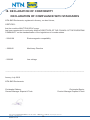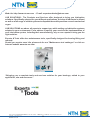
1
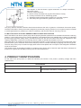
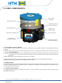
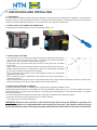
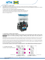
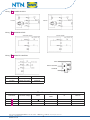
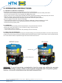
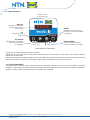
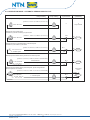
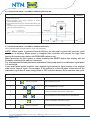
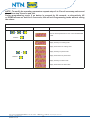
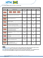
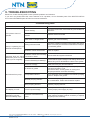
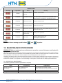
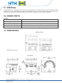
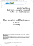
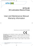
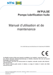
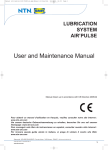
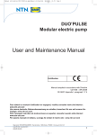
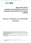
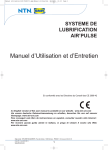
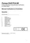
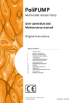
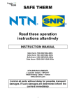
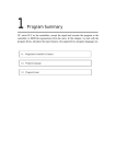
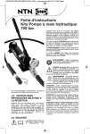
MULTI’PULSE AC
Lubrication pump for fixed
Industrial applications
User operation and Maintenance
manual
Warranty
Manual drawn up in accordance with EC Directive 2006/42
Pour obtenir ce manuel d'utilisation en français, veuillez consulter notre site Internet :
www.ntn-snr.com
Um unsere deutsche Gebrauchsanweisung zu erhalten, besuchen Sie uns auf unserer
Homepage: www.ntn-snr.com
Para conseguir este libro de instrucciones en español, consultar nuestro sitio Internet :
www.ntn-snr.com
Per ricevere questa guida utente in italiano, si prega di visitare il nostro sito Web:
www.ntn-snr.com
Siège social : NTN-SNR ROULEMENTS - Rue des Usines - 74000 Annecy - FRANCE - RCS Annecy B 325 821 072
Code APE - Code NACE 28.15
www.ntn-snr.com
1
1. TABLE OF CONTENTS
1.Table of contents
2.Introduction
3.General description
4.Product identification
5.Technical characteristics
6.Pump components
7.Unpacking and installing
8.Operating instructions
9.Troubleshooting
p.2
p.2
p.2
p.3
p.4
p.5
p.6
p.9
p.15
10.Maintenance procedure
11.Disposal
12.Spare Parts
13.Dimensions
13.Handling and transportation
14.Operating hazards
15.Precautions
16.Warranty
17.Declaration of conformity
p.16
p.17
p.17
p.17
p.18
p.18
p.19
p.19
p.20
2. INTRODUCTION
This user and maintenance manual refers to the MULTI’PULSE AC lubrication system.
This manual should be conserved in such a way that it remains undamaged over time and is readily available to personnel
needing to consult it.
The manufacturer reserves the right to update the product and/or the user and maintenance manual without the obligation
to revise previous versions.Further copies of this manual, updates or clarifications can be obtained by directly contacting
Experts & Tools at NTN-SNR Roulements, or to consult our web site at www.ntn-snr.com.
The use of the equipment referred to in this manual must be entrusted to qualified personnel with a basic knowledge
of mechanics, hydraulics and electrical systems.
It is the responsibility of the installer to use tubing suitable for the system; the use of inadequate tubing can cause
problems with the pump, injury to persons and create pollution.
Loosening of connections can cause serious safety problems; carry out a check before and after installation and,
if necessary retighten them.
Never exceed the maximum working pressure values permitted for the panel and the components connected to it.
Before any maintenance or cleaning operation disconnect the power supply, close off the airsupply and discharge
the pressure from inside the equipment and the tubing connected to it.
Do not subject the panel, the connections, the tubing or parts under pressure to violent impacts; damaged tubing
or connections are dangerous and should be immediately replaced.
After long periods of inactivity check air tightness of all parts subjected to pressure.
Personnel must use personal protection equipment, clothing and tools adequate for the location and the use of the panel
both during its operation and during maintenance operations.
The panel, and any accessories mounted on it, should be carefully checked immediately on receipt and in the event
of any discrepancy or complaint the NTN-SNR Roulements Sales department should be contacted without delay.
NTN-SNR Roulements declines to accept any responsibility for injuries to persons or damage to property in the event
of the non-observance of the information presented in this manual.
Any modification to component parts of the system or the different destination of use of this system or its parts without
prior written authorization from NTN-SNR Roulements will absolve the latter from any responsibility for injury to persons
and/or damage to property and will release them from all obligations arising from the guarantee.
3. GENERAL DESCRIPTION
3.1 CENTRALIZED LUBRICATION – GENERAL OPERATING INFORMATION
Centralized lubrication systems are designed to provide oil or grease to lubricating points on industrial or mobile
machinery. Such systems considerably reduce the cost of maintaining machinery on which they are installed, eliminating
machinery downtime caused by poor lubrication as well as prolonging the life of the machinery in general.
Additionally, a centralized lubrication system allows difficult to reach lubrication points to be lubricated at frequent intervals
that would otherwise be hard to access under normal conditions.
Siège social : NTN-SNR ROULEMENTS - Rue des Usines - 74000 Annecy - FRANCE - RCS Annecy B 325 821 072
Code APE - Code NACE 28.15
www.ntn-snr.com
2
The diagram on the left shows a typical schematic of a simple centralized
lubrication system.
The main components are:
A – Electric Pump with Reservoir (eg. MULTI’PULSE AC Pump).
B – Primary lubrication line for distributing grease.
C – Distributor elements that meters grease into a number of points.
D – Secondary tubing that delivers grease to the lube point.
The pump feeds a distributor element that shares and doses the ratio of grease or oil between the several points.
The MULTI’PULSE AC Pumps have been designed to provide the pumping solution for such systems used in industrial
or mobile applications for greases up to NLGI 2 consistency and oils with minimum viscosity of 46 cSt.
3.2 MULTI’PULSE AC ELECTRIC GREASE PUMP FOR FIXED APPLICATIONS
MULTI’PULSE AC is an electric piston pump with the pumping element operated from a camshaft connected to a reducing
gearbox. It can be fitting with up to 3 pumping elements (1 as standard) which are available with or without an integrated
pre-set bypass (pressure safety valve). The MULTI’PULSE AC also has a modular build reservoir supplied in 5 liter
capacity. Additionally a minimum level sensing device is fitted as standard at the base of the unit.
MULTI’PULSE AC is available as both with an integrated automatic control board that controls and monitors the pump
and lubrication cycle or a manual version where the pump motor is controller externally by applying and removing power.
The main body of the pump is made from high performance robust plastic and is compact in size designed to withstand
tough environments.
The grease version of the MULTI’PULSE AC includes a stirrer device with a reservoir wiper that help to eliminate air
present in the grease and facilitate pumping even at lower temperatures.
4. PRODUCT IDENTIFICATION
On the side of the pump there is a label that indicates part number of the product, operating voltage and basic
characteristics.
Accessories
LUBSO PUMPING ELEMENT AC
Pumpinp element Ø6mm with PSV integrated
LUBSO MULTIPULSE AC FIXING KIT
Kit to assemble the distributor
onto the MULTI’PULSE AC 110/230V pump
Siège social : NTN-SNR ROULEMENTS - Rue des Usines - 74000 Annecy - FRANCE - RCS Annecy B 325 821 072
Code APE - Code NACE 28.15
www.ntn-snr.com
3
5. TECHNICAL CHARACTERISTICS
General technical characteristics
AC - 50Hz
Operating voltage
AC - 60Hz
110 V
230 V
110 V
230 V
Current (nominal)
0,2 A
0,1 A
0,2 A
0,1 A
Current (peak)
0,3 A
0,2 A
0,3 A
0,2 A
Net weight with 5 Liter reservoir
7 kg (15.43 lb)
Number of outlets / pumping elements
1 as standard (3 max.)
Outlet thread
1/4” BSP
Nominal output per pumping element
2,8 cm³/min (0.17 in³/min) @ 20 RPM
Working pressure
Integrated By-pass pressure (for pumping elements with
integrated PSV)
Reservoir capacity
280 bar (4061 psi)
Max grease consistency
NLGI 2
Operating temperature
-25°C to +80°C
Storage temperature
-30°C to +90°C
Humidity
90 %
IP Protection level
IP 65
Noise level
< 70 dB (A)
320 bar ± 30 bar (4641 psi ± 435 psi)
5 liters (1.32 gallons)
Control panel characteristics
110VAC
Operating Voltage
230VAC
Includes internal transformer
Maximum Output load capability
5A
Short circuit & Overload protection
7.5A typical
Operating temperature
-20°C to +80°C
Storage temperature
-30°C to +90°C
10A max.
Overload protection on motor and lamp
Integrated Motor protection
l Spike voltage protection
l Inverted Polarity protection
l
l
Hardware protection
Memory for parameter storage
EEPROM
Memory Life
Unlimited (no battery requirement)
Minimum Level
Max load
AUTOMATIC version
0,3A
@
230V
MANUAL version
0,25A
@
120V
NOTE:Pump output has been determined at the following conditions: NLGI 2 Grease Standard
environmental conditions (Temperature 20°C / 68°F, Pressure 1 ATM), Back pressure 50 bar
(735 psi).
WARNING: Do not operate the unit outside the specified voltage ranges.
Siège social : NTN-SNR ROULEMENTS - Rue des Usines - 74000 Annecy - FRANCE - RCS Annecy B 325 821 072
Code APE - Code NACE 28.15
www.ntn-snr.com
4
6. PUMP COMPONENTS
Stirrer device
with wiper
Modular Reservoir
Connection point for
Pumping element 3
Pumping Element 1
Refilling point
grease nipple
Return port 1/8 BSP
Connector plate
Control panel
(automatic version)
Connection point for
Pumping element 2
6.1 ELECTRONIC CONTROL BOARD
In the automatic version, pump and cycle control is managed by the onboard controller. Three operating modes are
possible:
1. CYCLE: Lube and pause cycles are set using the built in timer or counting external inputs; the two condition work with
every combinations.
2. PULSE Lube Cycle and Pause cycle are determined by external inputs. During of Lube Cycle, the cycle sensor can
be monitored to ensure a correct system working. Pump can suspend the lube cycle if external pulses are
not found.
3. OFF: Pump works as slave regarding the control of the machine.
The MULTI’PULSE AC pump has been designed in order to integrate quickly Lubso distributors elements.
Programming instructions can be found in chapter 8 of this manual.
6.2 MINIMUM LEVEL
In manual version (no control board) the minimum level switch (Normally closed) opens when the minimum level
is reached. With the automatic (controlled) version, a voltage free changeover contact NC/NA can be obtained to give
a remote signal of minimum level.
6.3 CONNECTIONS & WIRING
A connector plate and wiring is available as standard. It is also possible to select another connector plate (consult
NTN-SNR Roulements).
Siège social : NTN-SNR ROULEMENTS - Rue des Usines - 74000 Annecy - FRANCE - RCS Annecy B 325 821 072
Code APE - Code NACE 28.15
www.ntn-snr.com
5
7. UNPACKING AND INSTALLING
7.1 UNPACKING
Once a suitable installation position has been identified, unpack the pump and prepare for installation. It is important to
inspect the pump to ensure that there has been no damage during transportation. The packaging material used does not
require any special disposal procedures. You should refer to you regional requirements.
7.2 INSTALLING THE CONNECTOR BASEPLATE
A base plate is delivered with the pump. See drawing chapter 7.7.1
Fig. 1
Fig. 2
7.3 INSTALLING THE PUMP
l In the box there is a mounting hole template as shown in the diagram here above.
This can be used to drill the fixing holes. The fixing holes should be Ø9mm
(Ø0.35 inch). Use 3 screws to fix the pump into place.
l Locate the pump so that the filling point and the control panel are accessible
by the user.
l Allow 100mm (4 inches) perimeter distance around the pump for easy access.
l Ideally, install the pump at a height that is easily and comfortably accessible
by the user to facilitate maintenance and refilling.
l Do not install the pump where it may be submerged by liquids of in excessively
aggressive environment.
l Do not install the pump in hazardous areas where there may be flammable or
explosive materials.
l Do not install near strong heat sources or electrical areas that may cause electrical interference with the control system.
l Ensure that tubing and wiring is appropriately secured and protected.
7.4 INSTALLING PUMPING ELEMENTS
The MULTI’PULSE AC pump is supplied with a single pumping element installed in Port 1.
Additional pumping elements can be installed on any of the additional pump port (2 or 3). It is also possible to move the
pumping element 1 to another port if necessary, to simplify piping arrangements on the lubrication system. To install a
new pumping element:
l Unscrew and remove the plastic plug with the O Ring that is installed on the standard product.
l Insert and screw the pumping element until it is fixed in position.
l Use 20Nm torque to secure the element.
WARNING: Based on the position of the internal cam drive it may be difficult to screw in the
pumping element as it compresses the return spring. In this case, use another outlet or of pay
particular attention when inserting the pump element and ensure that it does not cross-thread.
Siège social : NTN-SNR ROULEMENTS - Rue des Usines - 74000 Annecy - FRANCE - RCS Annecy B 325 821 072
Code APE - Code NACE 28.15
www.ntn-snr.com
6
7.5 HYDRAULIC CONNECTIONS
The hydraulic connection to the pump is via the pump outlets using adequate 1/4BSP fitting and tubing.
Additionally there is a 1/8” BSP port that can be used as a return line or a remote refilling line. Ensure that any refilling
system provides clean grease to the pump.
7.6 INSTALLING THE LUBSO DISTRIBUTOR DIVIDER VALVE
Under the base of the pump it is possible to install a LUBSO DISTRIBUTOR.
Use our kit for this purpose which contains 2 screws and a bent rigid tube.
Refer to the diagram below:
7.7 ELECTRICAL CONNECTIONS & WIRING
CAUTION: Before carrying out any electrical wiring you should check the label on the pump
to ensure that the correct operating voltage is being used and ensure that all power is
removed.
The electrical connection should be carried out by an electrician who has understood and identified the various connectors
and wiring that has been selected for the system (operating voltage, connector types, remote control, cycle sensors).
Connect the pump to the power supply using the appropriate power connector (refer to 7.7.1 Connector types) again
ensuring they are suitable for the selected voltage and frequency. The power cable should be adequately chosen to
ensure it can handle the current at the specified voltage.
On 110V/230VAC versions it is strongly recommended that a 1A fuse T and a differential trip is installed with an activation
level of 30 mA at 1 millisecond max. Isolation capability should be = 10kV minimum and nominal current ≥ 4Amps.
7.7.1 CONNECTOR TYPES
110V/230 V -50Hz / 60Hz VERSIONS :
A
D
A
C
C
C
Standard version
Automatic version
Siège social : NTN-SNR ROULEMENTS - Rue des Usines - 74000 Annecy - FRANCE - RCS Annecy B 325 821 072
Code APE - Code NACE 28.15
www.ntn-snr.com
7
Wiring
A
POWER SUPPLY
110VAC
Wiring
C
230VAC
MINIMUM LEVEL
Automatic version
Wiring
D
manual version
REMOTE CONTROL
LAMP
REMOTE CONTROL
COMMON
POWER
230 Vac
110 Vac
LAMP
12Vdc (3A max)
12Vdc (3A max)
OPTIONAL
0039433
0039433
Electric connetion
Connector
A
C
D
Nominal voltage
250 V - 300 V
150 V
230 V
Poles
3+
4
4
Cross section
cable
IP
Max. A
1 mm²
0,5 mm²
0,5 mm²
65
68
68
10 A
4A
4A
Siège social : NTN-SNR ROULEMENTS - Rue des Usines - 74000 Annecy - FRANCE - RCS Annecy B 325 821 072
Code APE - Code NACE 28.15
www.ntn-snr.com
8
8. OPERATING INSTRUCTIONS
8.1 BEFORE PUTTING INTO OPERATION
Note that the unit should not be dismantled by the user if a fault is found.
l Use gloves when handling lubricants and ensure you have checked the lubricant safety data sheet.
l Do not use lubricants that are incompatible with NBR (Buna) seals.
l Ensure that you have complied with all health and safety requirements before putting the pump into service.
l Maintain proper hygiene standards. Never ignore any potential danger to heath.
l Ensure all tubing and fittings are designed to handle the maximum system pressure.
l Check integrity in the pump. Ensure no damage;
l Check and fill the reservoir. If the reservoir is below the MIN level, follow procedure 8.3 to refill;
l Verify the pump is at the correct operating temperature and tubing is free of air bubbles;
l Check the unit is properly wired.
8.2 OPERATION
l Check and set the operating mode and parameter if using the automatic versions.
l Press the remote start button on your machine if using a manual version.
l Check that the pump is running.
l Check lubricant is being delivered to the greasing points as necessary.
8.3 REFILLING THE RESERVOIR
The refilling of the tank is carried out through the dedicated filling ports with adequate filtration to ensure clean lubricant.
Continue to fill unit until the max level is reached/ this level should not be exceed. In the event the user overfills the tank,
the excess lubricant will be expelled through vent holes located under the lid.
GREASE version
OIL version
Oil Filler Cap
Grease Filling Point
WARNING: To avoid introducing contamination into the pump and voiding the warranty
ensure that refilling is always carried out through the designated ports using clean grease.
Refer to 15 for more information about lubricant characteristics.
Siège social : NTN-SNR ROULEMENTS - Rue des Usines - 74000 Annecy - FRANCE - RCS Annecy B 325 821 072
Code APE - Code NACE 28.15
www.ntn-snr.com
9
8.4 CONFIGURATION
Automatic version
Control panel layout
DISPLAY
8.8.8.8.
Indicates the parameter
being programmed and
the set value
RESET
Resets the current lube cycle,
cancels any alarms and restarts
the program.
OK
Confirme la valeur
affichée
OK
RESET
UP ARROW
DOWN ARROW
Allows the user to increment
the setting value shown
on the display
Allows the user to decrease
the value shown on the display
Optional Remote Light Button
The light is constantly lit when the pump is running.
Flashes when a minimum level or other alarm is detected by the control system in the pump. The number of flashes
defines the anomaly code.
When pressed during the pause (standby) cycle, it will make the pump starts a lubrication cycle and then return to normal
automatic operation. The RESET of the pump is allowed when the button is pressed for 6 seconds.
8.4.1 OPERATING MODE :
The MULTI’PULSE Manual version does not have any adjustable feature as there is no local controller. You should
arrange to control the pump ON/OFF with a host system that activates the pump as required and monitors the lubrication
system, including checking level switch and cycle switch when installed.
Siège social : NTN-SNR ROULEMENTS - Rue des Usines - 74000 Annecy - FRANCE - RCS Annecy B 325 821 072
Code APE - Code NACE 28.15
www.ntn-snr.com
10
8.4.2 OPERATION MODE – AUTOMATIC VERSION MODE CYCLE
Pump stand by
Exemple 1) Timer based pause and lubrication cycle.
Pump working
ALARM
(TIMEOUT)
Cycle sensor
1 sec. - 99 min.
[P.Hou ≥ 1; P.Cou = 0; C.Min ≥ 1; C.Cou = 0;]
x
x
0 min / 99 hours
Only low level
Exemple 2) Timer based pause.
Lubrication cycle with monitoring of cycle sensor.
[P.Hou ≥ 1; P.Cou = 0; C.Min ≥ 1;C.Cou ≥ 1;]
Ok ?
0 min / 99 hours
No
STOP
yes
Exemple 3) Pause cycle determined by external impulse.
Lubrication cycle monitors cycle sensor.
[P.Hou = 0; P.Cou ≥ 1; C.Min ≥ 1; C.Cou ≥ 1;]
0 – 60.000 cycles
Ok ?
No
STOP
yes
Exemple 4) Pause determined by either time or extend impulse.
[P.Hou ≥ 1; P.Cou ≥ 1; C.Min ≥ 1;C.Cou ≥ 1;PTOA=OFF]
Ok ?
Whichever first
No
STOP
1 min / 99 hours
0 – 60.000 cycles
yes
Exemple 5) Pause determined by En
extend impulse, pause time generates
alarm if impulses not received.
[P.Hou ≥ 1; P.Cou ≥ 1; C.Min ≥ 1; C.Cou ≥ 1; PTOA=ON]
Pause time
overun
Alarm
1 min / 99 hours
1 – 60.000 cycles
No
yes
En
En
Siège social : NTN-SNR ROULEMENTS - Rue des Usines - 74000 Annecy - FRANCE - RCS Annecy B 325 821 072
Code APE - Code NACE 28.15
www.ntn-snr.com
STOP
Ok ?
11
8.4.3 OPERATION MODE – AUTOMATIC VERSION MODE PULSE
Pump stand by
Pump working
ALARM
(TIMEOUT)
Pause and lubrication cycle determined by external impulse
[P.Cou ≥ 0; C.Cou ≥ 1]
l During
lubrication, cycle sensor monitored to confirm
correct lubrication [C.Min ≥ 1]
● C.Min determines how many min. seconds to allow for the cycle
sensor.
● Lubrication cycle is suspended if external impulse not detected
within user preset time [S.Min ≥ 1]
l
8.4.4 OPERATION MODE – AUTOMATIC VERSION MODE OFF
Pump operates when external signal is given. No monitoring.
NOTE : When power is removed from the Bravo, the electronic control will save the cycle
condition in memory. When power is reapplied the controller will resume the logic from
exactly the same point (unless the PRELUBE option is set).
When powering on the system or when pressing the RESET button the display will the
firmware version of the unit for 2 seconds.
For all modes the Prelube parameter determines if the pump starts in a lubrication cycle when
it is set to ON.
Cycle and Pause inputs consider one complete cycle when the input returns to its original
state at the time of cycle. For example, if the switch is in the ON state at the start of the
lubrication cycle then it must change state to OFF, and then back to ON to count as one cycle.
SPECIAL FUNCTIONS AND PARAMETERS
STEP
1
BUTTONS
OK
DESCRIPTION
hold for 5 seconds
Enter programming mode
2
or
Select PARAMETER to change
3
OK
Confirm the selection and view the current value
4
or
Increment/Decrement VALUE/SETTING of PARAMETER
5
OK
Confirm value/setting and return to menu
6
OK
hold for 2.5 seconds
Save settings and exit programming mode
Siège social : NTN-SNR ROULEMENTS - Rue des Usines - 74000 Annecy - FRANCE - RCS Annecy B 325 821 072
Code APE - Code NACE 28.15
www.ntn-snr.com
12
NOTE : To modify the operating parameters repeats steps 2 to 5 for all necessary values and
then follow step 6 to save and exit.
During programming mode, if no button is pressed for 20 seconds, or alternatively UP
or DOWN arrows are held for 2.5 seconds, this will exit Programming mode without saving
the values.
SPECIAL FUNCTIONS AND PARAMETERS
BUTTONS
+
Release
+
DISPLAY
DESCRIPTION
Reset
Reset to default parameters for the current OPERATING
MODE
Reset
Display total days in working state
Display total minutes in working state
+
Release
Display total days in pause state
Reset
Display total minutes in pause state
Reset
Display total days in alarm state
Display total minutes in alarm state
Siège social : NTN-SNR ROULEMENTS - Rue des Usines - 74000 Annecy - FRANCE - RCS Annecy B 325 821 072
Code APE - Code NACE 28.15
www.ntn-snr.com
13
8.5 PROGRAMMING THE ELECTRICAL CONTROLLER
OPERATING PARAMATERS
DISPLAY
DESCRIPTION
MODE
DEFAULT
RANGE
CYCLE
PULSE
OFF
NOTES
Cyclo 100%
PAUSE TIMER: SET Hours and Minutes
CYCLE
10 min
0 min /
99 min
TIMER to suspend the cycle
PULSE
0 sec
0 sec /
99 min
PAUSE COUNTER:
number of divider switch cycles to wait in pause
CYCLE
PULSE
1 cycle
0/
60000
CYCLE TIMER:
if timed cycle it indicates the duration;
if cycle with control impulses, indicates the waited
maximum time of the single impulse before alarm.
CYCLE
PULSE
1 min
99 min /
1 sec
CYCLE COUNTER: number of divider switch
cycles per lubrication cycle. input used:
l Sensor Cycle if Cycle Mode
l Sensor Pause if Pulse Mode
CYCLE
PULSE
1 cycle
0/
60000
PRELUBE: Start – controller in Lubrication mode
when powered on.
CYCLE
PULSE
OFF
ONOFF
Motor DUTY:
allows reduction in pump output by adjusting
motor speed
CYCLE
PULSE
OFF
100
100 /
50
Number of cycles given from the manual input
(it allows eventual filling system)
CYCLE
PULSE
1
0/
9999
If OFF, to expiring of the pause time,
stars the lubrication cycle.
If ON, to expiring of the pause time,
gives Pause Time Overrun alarm.
CYCLE
OFF
ONOFF
Both
Complet cycle
Complet cycle
NOTE :
Continuous Cycle: Continuous cycle can be achieved by setting the pause timer to zero.
Complete cycle: Valid on input full cycle ON>OFF>ON or OFF>ON>OFF.
Both: When the pause timer is set to non zero, the system operates in a combined mode.
The cycle will start EITHER on impulse Count OR Pause Time being reached.
Siège social : NTN-SNR ROULEMENTS - Rue des Usines - 74000 Annecy - FRANCE - RCS Annecy B 325 821 072
Code APE - Code NACE 28.15
www.ntn-snr.com
14
9. TROUBLESHOOTING
Below is a trouble shooting table to show possible problems and solutions.
If you are in any doubt about the correct solution to fix a problem, do not dismantle parts of the MULTI’PULSE AC
but contact NTN-SNR Experts & Tools for technical assistance.
Troubleshooting table
Problem
Pump Motor does not
operate
Pump is operating but no
lubricant reachespoints
Possible cause
Remedial action
Power missing
Check the power lines, ensure that any fuse installed is
still intact
Electronic Controller does not
function
Replace electronics board
Gear motor no longer works
Replace gear motor assembly
Tubing is disconnected
Check the condition of tubing in the system and ensure
that it is correctly secured and not blocked for example,
by hardened grease.
Distributor valves are blocked
Clean or replace.
Distributor valves are incorrectly
Check valves and system schematic
Lubricant does not reach connected or sized
lubrication points on each
Ensure that the system designs and settings allow for at
pump cycle or irregularly
Incorrect Pause/Cycle Settings
least a full cycle for all distributor valves in the system
Reservoir is empty
Refilll, and verify any low level alarms
Air bubble in grease
Disconnect the primary tubing from the pump and
operate a lubrication cycle.
Check that clean, air free grease is coming from
the pump and then reconnect the tubing.
Incompatible lubricant.
Some lubricants are not suitable for automatic pumping
systems. Replace the grease.
Blocked pumping element
Dismantle the pumping element and check
for contamination. Clean and reinstall or repalce.
Worn pumping element
Replace pumping element
The display is not lit
Incorrect power/voltage
Check power and voltage.
Ensure proper power supply to pump.
The pump starts the
lubrication cycle but
then immediately stops
Defective or blocked Pump
motor
No lubricant from pump
Allow the pump to cool. Retry the lubrication cycle.
If the problem persists It will be necessary to replace
the pump motor assembly.
Siège social : NTN-SNR ROULEMENTS - Rue des Usines - 74000 Annecy - FRANCE - RCS Annecy B 325 821 072
Code APE - Code NACE 28.15
www.ntn-snr.com
15
Alarm codes
Message
Light button
Alarm
Remedy
1 Flash
Low lubricant level in
reservoir
2 Flashes
Cycle Sensor overrun
The cycle sensor was not received within the specified
time. Ensure Timer overlong is set to approriate value
and that there is no problem on the lubrication circuit.
3 Flashes
Pause timer overun
Verify input pause sensor
4 Flashes
Pump Motor Blocked
Replace the motor unit
5 Flashes
Pump Motor Over-load
Allow system to cool, if the problem still goes on go on,
replace the motor unit
6 Flashes
C.COU pulses counter
in Pulse Mode
Modify C.COU parameter
7 Flashes
Eprom Error
Electronic Board memory error.
Board requires replacement
NOTE :
To cancel alarm message push buttons
and
Refill with clean lubricant
together.
10. MAINTENANCE PROCEDURE
WARNING: Before carrying out any maintenance operation, ensure that power and hydraulic
system are disconnected.
The MULTI’PULSE AC pump does not require any special tool for operation and maintenance. When working with the
MULTI’PULSE AC pump it is nonetheless recommended that personal health and safety equipment is used as it is normal
for any operation in an industrial or similar workplace to best safeguard the user from harm.
The MULTI’PULSE AC pump has been designed and built as to require minimal maintenance and operate in diverse and
challenging operating environment. It is recommend that the unit is inspected and kept clean to ensure long life and
trouble free operation. It is important to check all tubing on the system to ensure that it is always tight and leak free.
10.1 OPERATIONAL MAINTENANCE
The following operations should be performed on the pump.
Item
Frequency
Operation
Integrity of tubing
and system
After initial 500 hours.
Every1500 hours.
Check fittings and tubing secured.
Verify components are correctly fixed to machine.
Reservoir level
Filling Filter
As needed
As needed, or once per year
Top up level with clean lubricant
Check and replace as necessary
Siège social : NTN-SNR ROULEMENTS - Rue des Usines - 74000 Annecy - FRANCE - RCS Annecy B 325 821 072
Code APE - Code NACE 28.15
www.ntn-snr.com
16
11. DISPOSAL
During maintenance or disposal of the machine care should be taken to properly dispose of environmentally sensitive
items such as oils or other lubricants. Refer to local regulations in force in your area. When disposing of this unit,it is
important to ensure that the identification label and all the other relative documents are also destroyed.
12. SPARE PARTS
OPTION
Reference
Description
Lubso pumping element AC
Multipulse fixed flow pump 110/230VAC
Lubso Multipluse AC fixing kit
Kit to assemble the distributor onto the Multipulse AC 110/230V pump
Lubso Multipluse AC tank segment
Tank extension
13. DIMENSIONS
Grease version
Dimensions in mm [in].
Oil version
Siège social : NTN-SNR ROULEMENTS - Rue des Usines - 74000 Annecy - FRANCE - RCS Annecy B 325 821 072
Code APE - Code NACE 28.15
www.ntn-snr.com
17
14. HANDLING AND TRANSPORTATION
Prior to shipping, the equipment is carefully packed in cardboard package. During transportation and storage, always
maintain the pump the right way up as indicated on the box. On receipt check that package has not been damaged. Then,
store the machine in a dry location.
15. OPERATING HAZARDS
WARNING: It is necessary to carefully read the instructions and the risks involved in the use
of lubrication machines. The operator must know the machine functioning through the User
and Maintenance Manual.
Electric currents
No intervention must be attempted on the equipment without first having disconnected the electrical power supply and
ensuring that it cannot be reconnected during the intervention.
All installed equipment, electrical, electronic, tank and base structure, must be connected to the ground line utilizing the
terminals fitted to each component.
Flammability
The oil employed in the lubrication circuit is not normally flammable. It is nonetheless indispensable to take every
precaution against the oil coming into contact with very hot parts or open flames.
Pressure
Prior to any intervention on the equipment ensure that pressure is released from all branches of the lubrication circuit.
Failure to do this could result in oil being discharged under pressure where connections or components are disassembled
Noise
The MULTI’PULSE AC lubrication panel does not emit excessive noise, remaining below 70dB(A).
WARNING: before carrying out the replacement of the mini-pumps, empty the tank of lubricant.
15.1 LUBRICANTS
NOTE: The pump has been designed to operate with max NLGI 2 grease or min 46cst Oil
(oil version). Always use lubricants compatible with NBR (Buna) rubber seals.
Any residual lubricant found on new units is residual NLGI 2 test grease used during
the assembly of the pump.
The following table shows the comparison between NLGI (National Lubricating Grease Institute) classification and ASTM
(American Society for Testing and Materials) for greases and cSt (Centi stokes) e SUS (Saybolt Universale) for oil.
Grease
Oil
NLGI
ASTM
cSt
SUS
000
445 - 475
46
213,3
00
400 - 430
70
323
0
355 - 385
100
462,6
1
310 - 340
150
694,2
2
265 - 295
220
1018
320
1480
450
2082
700
3239
1000
4628
For further technical information and on safety
information consult the lubricant MSDS Safety data
sheet or equivalent document supplied by the
lubricant manufactuer.
Siège social : NTN-SNR ROULEMENTS - Rue des Usines - 74000 Annecy - FRANCE - RCS Annecy B 325 821 072
Code APE - Code NACE 28.15
www.ntn-snr.com
18
16. PRECAUTIONS
The verification of conformity with the essential safety requirements and regulations of the Machine Directive is effected
by means of the compilation of a check list which has been pre-prepared and is contained in the technical file.
The lists which are utilised are of three types:
l list of dangers (appendix A, EN 1050).
l application of essential safety requirements (Machine Dir. - att. 1, part 1).
l electrical safety requirements (EN 60204).
The following is a list of dangers which have not been fully eliminated but which are considered
acceptable:
l During installation there may be low pressure oil coming from the pump. Always use appropriate protective clothing,
gloves and take all necessary safety precautions.
l Contact with lubricant during maintenance or filling of the reservoir.
As per previous point, correct precautions must
be taken to protect from contact with lubricant.
l Moving Parts and crush danger : All moving parts are enclosed within the pump unit. Do not open the pump unit.
Appropriate danger labels are located on the pump.
l Electric shock : All electrical connections must be carried out by a qualified electrician who hasstudied the connection
to remove electrical danger.
l Abnormal operation posture : The pump should be installed in a suitable position with ample clearance as indicated in
this manual to avoid abnormal posture for the operator.
l Unsuitable Lubricant. : Lubricant characterstics are indicated on the pump and in this user manual. In any case contact
a NTN-SNR Support engineer.
Fluids explicitly not allowed
Fluids
Danger
Lubricants with abrasive additives
Lubricants with silicone based additives
Petrol – solvents – inflammable liquids
Corrosive products
Water
Food substances
High wear rate of contacted parts
Seizure of the pump
Fire – explosion – damage to seals
Corrosion of the pump– injury to persons
Oxidation of the pump
Contamination of the substances themselves
17. WARRANTY
All products manufactured and marketed by NTN-SNR Roulements are warranted to be free of defects in material or
workmanship for a period of at least 12 months from date of delivery.
Extended warranty coverage applies if complete system installation by NTN-SNR Roulements: 12 Months.
If a fault occurs, notify NTN-SNR giving:
- a complete description of the alleged malfunction
- the part number(s)
- date of delivery
- date of installation
- operating conditions of subject product(s)
We will subsequently review this information and supply you with either servicing data or shipping instruction and returned
materials authorization (RMA) which will have instructions on how to prepare the product for return.
NTN - SNR Roulements reserves to right to charge an administration fee if the product(s) returned are found to be not defective.
This limited warranty does not cover any products, damages or injuries resulting from misuse, neglect, normal expected
wear, chemically caused corrosion, improper installation or operation contrary to factory recommendation. Nor does it
cover equipment that has been modified, tampered with or altered without authorization.
Consumables and perishable products are excluded from this or any other warranty.
No other extended liabilities are stated or implied and this warranty in no event covers incidental or consequential
damages, injuries or costs resulting from any such defective product(s).
The use of NTN-SNR product(s) implies the acceptance of our warranty conditions. Modifications to our standard warranty
must be in made in writing and approved by NTN-SNR Roulements.
Siège social : NTN-SNR ROULEMENTS - Rue des Usines - 74000 Annecy - FRANCE - RCS Annecy B 325 821 072
Code APE - Code NACE 28.15
www.ntn-snr.com
19
18. DECLARATION OF CONFORMITY
DECLARATION OF COMPLIANCE WITH STANDARDS
NTN-SNR Roulements, registered in Annecy, rue des Usines,
CERTIFIES :
that the machine MULTI’PULSE AC pump,
has been constructed in conformity with the DIRECTIVES OF THE COUNCIL OF THE EUROPEAN
COMMUNITY on the standardization of the legislations of member states:
- 2004/108
Electromagnetic compatibility
-- 2006/42
Machinery Directive
- 2006/95
Low voltage
---------------------------------------------------------------------------------------------------------------------------------Annecy, July 2010
NTN-SNR Roulements
Christophe Oddoux,
General Manager Experts & Tools
Christophe Benier,
Product Manager Experts & Tools
Siège social : NTN-SNR ROULEMENTS - Rue des Usines - 74000 Annecy - FRANCE - RCS Annecy B 325 821 072
Code APE - Code NACE 28.15
www.ntn-snr.com
20
Web site: http://www.ntn-snr.com - E-mail: [email protected]
LUB SOLUTIONS : The Products and Services offer designed to bring you lubrication
solutions. Specifically selected for your different applications, a choice of lubricants is offered
as well as a full range of reliable systems to dispense them with precision on each mechanical
organ.
LUB SOLUTIONS are above all experts to support you while setting up lubrication systems
adapted to your environment. From advices to specify your needs to the implementation of
your lubrication system, including their manufacturing, rely on our experts to bring you the
right solution.
Experts & Tools offer also maintenance tools, specifically designed for bearing fitting and
removal.
Should you require more info, please ask for our "Maintenance tool catalogue" or visit our
Internet website www.ntn-snr.com
“Bringing you a complete tools and services solution for your bearings, suited to your
application, size and resources.”
Siège social : NTN-SNR ROULEMENTS - Rue des Usines - 74000 Annecy - FRANCE - RCS Annecy B 325 821 072
Code APE - Code NACE 28.15
www.ntn-snr.com
21