1
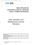
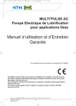
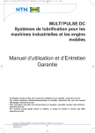
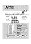
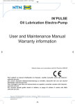
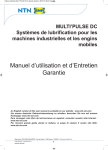
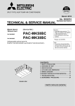
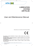
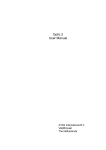
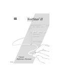
Manuel utilisation DUO PULSE en.qxp:Manuel utilisation
24/01/11
11:55
Page 1
DUO’PULSE
Modular electric pump
User and Maintenance Manual
Certification
Manual compiled in accordance with Directive
C2116IE – WK 50/09
CE 98/37 Appendix I, paragraph 1.7.4
Pour obtenir ce manuel d'utilisation en espagnol, veuillez consulter notre site Internet :
www.ntn-snr.com
Um unsere deutsche Gebrauchsanweisung zu erhalten, besuchen Sie uns auf unserer Homepage: www.ntn-snr.com
Para conseguir este libro de instrucciones en español, consultar nuestro sitio Internet :
www.ntn-snr.com
Per questo manuale in italiano, si prega de visitare il nostro sito : www.ntn-snr.com
Siège social : NTN-SNR ROULEMENTS - Rue des Usines - 74000 Annecy - FRANCE - RCS Annecy B 325 821 072
Code APE 2815Z - Code NACE 28.15
www.ntn-snr.com
1
Manuel utilisation DUO PULSE en.qxp:Manuel utilisation
1. CONTENTS
1.Contents
2.Introduction
3.General description
4.Identification of the pump
5.Technical characteristics
6.Pump components
7.Unpacking and installation
8.Instructions for use
9.Problems and solutions
2. INTRODUCTION
24/01/11
p.2
p.2
p.2
p.3
p.3
p.5
p.10
p.10
p.16
11:55
Page 2
10.Maintenance procedures
11.Disposal
12.Information about ordering
13.Dimensions
14.Handling and transport
15.Precautions for use
16.Contraindications for use
17.Guarantee
18. Declaration of conformity
p.18
p.18
p.18
p.22
p.22
p.22
p.22
p.23
p.24
This user and maintenance manual refers to the DUO’PULSE air/oil lubrication system.
This manual should be conserved in such a way that it remains undamaged over time and is readily available to personnel
needing to consult it.
The manufacturer reserves the right to update the product and/or the user and maintenance manual without the obligation to revise previous versions.Further copies of this manual, updates or clarifications can be obtained by directly contacting Experts & Tools at NTN-SNR Roulements, or to consult our web site at www.ntn-snr.com.
The use of the equipment referred to in this manual must be entrusted to qualified personnel with a basic knowledge of
mechanics, hydraulics and electrical systems.
It is the responsibility of the installer to use tubing suitable for the system; the use of inadequate tubing can cause problems with the pump, injury to persons and create pollution.
Loosening of connections can cause serious safety problems; carry out a check before and after installation and, if necessary retighten them.
Never exceed the maximum working pressure values permitted for the panel and the components connected to it.
Before any maintenance or cleaning operation disconnect the power supply, close off the airsupply and discharge the
pressure from inside the equipment and the tubing connected to it.
Do not subject the panel, the connections, the tubing or parts under pressure to violent impacts; damaged tubing or
connections are dangerous and should be immediately replaced.
After long periods of inactivity check air tightness of all parts subjected to pressure.
Personnel must use personal protection equipment, clothing and tools adequate for the location and the use of the panel
both during its operation and during maintenance operations.
The panel, and any accessories mounted on it, should be carefully checked immediately on receipt and in the event of
any discrepancy or complaint the NTN-SNR Roulements Sales department should be contacted without delay.
NTN-SNR Roulements declines to accept any responsibility for injuries to persons or damage to property in the event of
the non-observance of the information presented in this manual.
Any modification to component parts of the system or the different destination of use of this system or its parts without
prior written authorization from NTN-SNR Roulements will absolve the latter from any responsibility for injury to persons
and/or damage to property and will release them from all obligations arising from the guarantee.
3. GENERAL DESCRIPTION
The DUO’PULSE lubrication pump may be adapted to many uses without making any mechanical changes even after
it has been installed. In fact, the pressure, quantity of lubricant delivered, actual type of lubricant or type of distribution
can be altered.
Its design is essentially based on the following modules:
•Electric motor
•Pump body with integrated reducer
•Two pumping elements
•Reservoir
•Valves and outlet unit (inverter, pressure adjustment valve, etc.).
Siège social : NTN-SNR ROULEMENTS - Rue des Usines - 74000 Annecy - FRANCE - RCS Annecy B 325 821 072
Code APE 2815Z - Code NACE 28.15
www.ntn-snr.com
2
Manuel utilisation DUO PULSE en.qxp:Manuel utilisation
24/01/11
11:55
Page 3
There is only one pumping structure for all versions, with the dual pumping element constituting the essential module.
The pump unit possesses one single output, because the deliveries from the two pumping elements flow into one manifold unit.
The pump has an electrical controller which is able to effect inversion and perform the programmed cycles.
The DUO’PULSE electric pump is fully protected against the external environment and can operate without difficulty
under the most severe environmental conditions.
DUO’PULSE 100 kg
DUO’PULSE 30 kg
Picture 1
Picture 2
4. IDENTIFICATION OF THE PUMP
On the front part of the pump tank,a plate indicates the product code, the supply voltage and the basic characteristics.
5. TECHNICAL CHARACTERISTICS
Max. pressure
400 bars
Working temperature
From - 5° C to + 50° C (from 23° F to +122° F)
Outlet delivery
Working humidity
Viscosity at working temperature
Grade
Protection level
Electric motor
400 cm3 / min (24 cu. in/min)
(2 x 200 cm3 (12 cu. in) for each pump module)
90% max
Mineral oil lubricants
Min. 32 cSt
Grease lubricants
NGLI 2 Max.
IP 55
Three phase
Power 0.75kW
Protection IP55 class B
Voltage: 230-400 VAC ± 5% 50 Hz
240-440VAC ± 5% 60 Hz
S1 continuous service.
N.B.: do not supply the machine with different voltages and pressures from those indicated
on the plate.
Siège social : NTN-SNR ROULEMENTS - Rue des Usines - 74000 Annecy - FRANCE - RCS Annecy B 325 821 072
Code APE 2815Z - Code NACE 28.15
www.ntn-snr.com
3
Manuel utilisation DUO PULSE en.qxp:Manuel utilisation
5.1 HYDRAULIC FUNCTION DIAGRAM
24/01/11
11:55
Page 4
Standard grease pump (dual line)
Standard oil pump (dual line)
Single outlet grease pump (option)
Single outlet oil pump (option)
Siège social : NTN-SNR ROULEMENTS - Rue des Usines - 74000 Annecy - FRANCE - RCS Annecy B 325 821 072
Code APE 2815Z - Code NACE 28.15
www.ntn-snr.com
4
Manuel utilisation DUO PULSE en.qxp:Manuel utilisation
24/01/11
11:55
Page 5
Grease pump (options: dual line, electropneumatic inverter) Oil pump (options: dual line, electropneumatic inverter).
6. PUMP COMPONENTS
6.1 FIXED DELIVERY PUMPING ELEMENTS
The pump has two standard pumping elements (200 cm3/ min for each pumping element). A piston slides inside the body
of the pumping element coupled to the latter by a lapping process. The seal between the piston and the pumping body
is of dry type, with no gasket provided between the two. The pumping element retention valve has a tapered seal This
solution is able to guarantee an optimum seal for the system at high operating pressures (max. pressure 400 bar). The
pumping elements are assembled on the manifold unit with a threaded attachment, which facilitates its assembly/ dismantling.
6.2 ENDLESS SCREW / WORM WHEEL UNIT
The pump has endless screw-worm wheel working kinematics with a transmission ratio of 1/40. The screw is made from
special steel with high mechanical resistance. To guarantee high resistance to wear, the screw has been subjected to
Tenifer wear-resistant treatment. The screw is supported by angular contact ball bearings, duly preloaded, to reduce
working clearance. The worm wheel is made of bronze alloy for gear systems, particularly suitable for making the pump
run quietly. The worm wheel shaft is made of special high resistance steel which gives the pump better reliability and durability.
6.3 INVERTORS
The standard pump is prepared for dual line function, with an electromagnetically controlled inverter as standard. The
inverter can be replaced, without disconnecting the two line pipes (of an interchangeable type). This is able to reduce
maintenance times and the relating installation shutdown.
GENERAL NOTE FOR ALL INVERTERS: It is advisable to plan a delay in the de-energizing of
the electromagnets of 2 - 5 sec. to allow complete inversion in relation to the closing time of
the pressure gauge at the end of the line.
Siège social : NTN-SNR ROULEMENTS - Rue des Usines - 74000 Annecy - FRANCE - RCS Annecy B 325 821 072
Code APE 2815Z - Code NACE 28.15
www.ntn-snr.com
5
Manuel utilisation DUO PULSE en.qxp:Manuel utilisation
24/01/11
11:55
Page 6
Exchanging the inverter without disconnecting the line
pipes. A solution of this type offers the following advantages:
•Ease of assembly and dismantling (only the 4 front Allen
screws need to be loosened and tightened);
•Short replacement time;
•Minimum installation shutdown time.
Code
Spare parts
Description
Electrovalve 24V DC
Current (A)
Power (W)
2
206
Electrovalve 110V AC 50/60 Hz
Electrovalve 230V AC 50/60 Hz
Seal kit
Code
7
170
1
Spare electrovalves
Solenoid 24V DC
176
Description
Solenoid 24V AC 50/60 Hz
Solenoid 110V AC 50/60 Hz
Solenoid 230V AC 50/60 Hz
6.4 PRESSURE CONTROL VALVE MOUNTED ON THE PUMP
The pump has a pressure control valve, mounted on the
manifold unit on the right side of the pumping elements.
The valve can be easily dismantled for inspection if required. It is calibrated by turning the bypass pressure adjustment nut:
•
clockwise (increase of pressure)
•
anticlockwise (decrease of pressure)
Once the bypass has been calibrated, the position of the
pressure adjustment nut is locked using a lock nut. It is important to bear in mind that line inversion is controlled by
closing the contacts of the pressure switch. Adjusting the
pressure switch provides an operating pressure which is
lower than the maximum pressure controlled by this valve.
Code
Bypass pressure
adjustment nut
Picture 4
Extractible pumping elements
Descripition
Pressure 100 to 450 bar (1470 ÷ 6615psi)
Pressure 50 to 200 bar (735÷ 2940 psi) on request
Siège social : NTN-SNR ROULEMENTS - Rue des Usines - 74000 Annecy - FRANCE - RCS Annecy B 325 821 072
Code APE 2815Z - Code NACE 28.15
www.ntn-snr.com
6
Manuel utilisation DUO PULSE en.qxp:Manuel utilisation
24/01/11
11:55
Page 7
6.5 PUMPING ELEMENTS WITH FIXED AND VARIABLE FLOW
The standard pump has two pumping elements with fixed flow (Image 1). On request it is possible to have a solution with
variable flow (Image 2). The pump can offer variable flow by replacing a fixed flow pumping element with a variable flow
one.
Ref.
Code
Picture 1
Picture 2
Description
Pumping element with variable flow 100- 200 cm3/min
Pumping element with fixed flow 200 cm3/min
The main parts of the pumping element with variable flow are:
•External body of the pumping element assembled with seal threading on the manifold group;
•Internal body of the pumping element equipped with flow adjustment with threaded screws;
•Piston;
•Non-return valve with tapered cone seal system;
•Spring which guarantees contact between the piston and the excentric gear.
Ref.
Code
Description
Code
Fixed pumping element unit
Picture 1
Variable pumping
element unit
Picture 2
Description
OR 2187 gasket in polyurethane CHPU95
Stop valve cap
Tapered spring
Valve cone
Gasket OR 2187 in polyurethane CHPU95
Gasket OR 3156 in polyurethane CHPU95
Gasket OR 3118 in polyurethane CHPU95
Stop valve cap
Tapered spring
Valve cone
Variable flow pumping element
Fixed flow pumping element
Drawing 1
Drawing 2
Siège social : NTN-SNR ROULEMENTS - Rue des Usines - 74000 Annecy - FRANCE - RCS Annecy B 325 821 072
Code APE 2815Z - Code NACE 28.15
www.ntn-snr.com
7
Manuel utilisation DUO PULSE en.qxp:Manuel utilisation
24/01/11
11:55
Page 8
6.6 ADJUSTMENT OF PUMPING ELEMENT DELIVERY.
Flow is adjusted by unscrewing (reducing flow) or tightening (increasing flow) the internal pumping element.Each complete turn corresponds to an 11.5% change in delivery. There are two on the fixed and mobile pumping element bodies
(Picture 5) which allow identification of rotation at every ¼ turn (90°). The internal pumping element possesses a threaded adjustment of M36x2: each complete turn corresponds to an adjustment of the pumping element stroke of 2 mm. X
is the reference height obtained with calibration, between the exterior of the fixed pumping element and the exterior of
the internal pumping element. Y is the actual displacement of the internal pumping element (Y=13-X).
X height measured mm
13
Effective pumY= 13-X pumping % variation of de- Actual stroke of
ping element delielement adjust- livery per pum- pumping element
very
ment stroke
ping element
mm
Cm3/ min
0
11
9
5
17.5
200
23
13.5
154
2
11.5
6
34.5
4
7
0
8
15.5
11.5
46
9.5
N.B:. Flow values are valid in the absence of outgoing counterpressure.
Picture 5
Picture 6
6.7 MAXIMUM AND MINIMUM GREASE LEVEL INDICATORS
Standard grease pumps indicate two types of level:
•Minimum capacitive level;
•Maximum visual level (float).
Code
176
132
108
Drawing 3
Description
Maximum visual level kit (float)
Minimum capacitive level kit for 30kg tank (68.1 lb.)
Minimum capacitive level kit for 100kg tank (100.02 kg.)
Capacitive probe
6.7.1 Minimum capacitive level
The minimum level is controlled by a capacitive probe, positioned on the end of a pipe mounted on the tank cover. The
capacitive probe is normally closed. When it reaches the minimum level the probe indicates a lack of lubricant. To
make the solution valid for NLGI2 grease as well, the capacitive probe interfaces with the scraper whose function is to
clean the lower face of the grease probe. If the capacitive probe is replaced then it must be recalibrated (see calibration procedure).
The minimum level contact is indicated by a light signal on the control panel. In addition it can control to automatically
refill the tank.
6.7.2. Maximum visual level (floating)
The phase for loading the lubricant into the tank is carried out by the operator, with an appropriate pump. Once the
maximum level of lubricant has been reached, a small floating rod indicates that the tank is full.
Siège social : NTN-SNR ROULEMENTS - Rue des Usines - 74000 Annecy - FRANCE - RCS Annecy B 325 821 072
Code APE 2815Z - Code NACE 28.15
www.ntn-snr.com
8
Manuel utilisation DUO PULSE en.qxp:Manuel utilisation
24/01/11
11:55
Page 9
6.8 INDICATORS OF MINIMUM AND MAXIMUM OIL LEVEL.
Standard oil pumps indicate two types of level:
•Minimum and maximum level float;
•Maximum visual level (float).
Code
Description
Maximum visual level kit (float)
Maximum visual level float
Level float kit for 30 kg tanks (68.1 lb.) (minimum and maximum level)
Level float kit for 100 kg tanks (68.1 lb.) (minimum and maximum level)
6.8.1 Minimum and maximum level float
A probe rod with dual float mounted on the pump cover provides a reading of the minimum oil level (reserve) and the maximum level (which allows the automatic refilling of the tank to be stopped).
The minimum level contact is indicated by a light signal on the control panel. In addition it can control to automatically
refill the tank.
6.8.2. Maximum visual level (floating)
See point 6.7.2.
6.7 STIRRING PADDLE FOR GREASE AND OIL (STANDARD PERFORMANCE)
Tanks are provided with a capacity of 30 and 100 kg. (22 – 66.1 – 220.4 lb) : two for oil and two for grease.
The tanks have a stirring paddle and scraper as standard, and they must not be dismantled when they are being assembled and replaced. Under the stirring paddle a galvanized steel mesh with 0.5 mm holes (0.02 in.) is provided as standard. In this way the pump is protected from any foreign bodies which might be inadvertently present during the tank
refilling process.
6.8 PRESSURE GAUGE
The pressure gauge is of the glycerin filled type, so it is protected from any pressure leaks which might damage its functioning. It is mounted directly in the manifold block (positioned on the front of the pump).
Code
6.9 ELECTRICAL CONTROL PANEL
Description
1000 bar ( 0 -14.700 psi)
The electrical control panel has been designed to provide a complete system complete with all the controls necessary
for automatic functioning controlled by safety signals from centralized lubrication installations. The primary voltage is
400 VAC at 50 Hz (other voltages on request).
Type of probe
CAPACITIVE PROBE
LASER PROBE
Type of inverter
electromagnetic
electropneumatic
electromagnetic
electropneumatic
Voltage V
24 VDC
110 VAC
220 VAC
24 VDC
110 VAC
220 VAC
24 VDC
110 VAC
220 VAC
24 VDC
110 VDC
220 VDC
Code Electrical
apparatus
Siège social : NTN-SNR ROULEMENTS - Rue des Usines - 74000 Annecy - FRANCE - RCS Annecy B 325 821 072
Code APE 2815Z - Code NACE 28.15
www.ntn-snr.com
Code Electric
diagram
9
Manuel utilisation DUO PULSE en.qxp:Manuel utilisation
24/01/11
11:55
Page 10
7. UNPACKING AND INSTALLATION
WARNING: The unit is only to be opened and repaired by skilled technicians.
No pump assembly operations are requested. The pump is fixed on a metal plate, which allows safe handling using a
forklift. This plate has been equipped with 4 holes of Ø 14 mm suitable for fixing on the floor. Provide adequate space
(as shown on the installation diagram) to avoid abnormal posture or possible impact. Then, as described previously, the
pump must be connected hydraulically to the machine and then connected to the control panel.
8. INSTRUCTIONS FOR USE
8.1 GOING INTO OPERATION
Damage to the supply cable and housing may involve contact with high voltage live parts and consequently fatal danger:
•Check the integrity of the supply cable and the unit prior to use;
•If the supply cable or the unit is damaged, do not start up the system!
•Replace the damaged supply cable with a new one;
•The unit can be opened and repaired only by skilled technicians;
•In order to prevent the danger of electrocution due to direct or indirect contact with live parts the electric supply line must
be adequately protected by an appropriate magnetothermal differential 30mA circuit breaker max response time of 1 second;
•The switching capacity must be ? 10 kA and rated current In = 6 A.
•The pump must not be used when submerged in fluids or in a particularly aggressive or explosive/inflammable atmosphere unless prepared in advance for this purpose by the supplier;
•To fix the pump correctly check the pitch dimensions shown in the figures in chapter 12;
•Use safety gloves and goggles as indicated in the safety sheet for the lubrication oil;
•Do NOT use lubricants which are aggressive for NBR gaskets, and if in doubt consult NTN-SNR Bearings which will supply a detailed list of the recommended oils;
•Do not ignore dangers to health and comply with health and safety regulations;
•Warning! All the electric components must be grounded correctly. This applies to both the electric components, and to
the control devices. To this end make sure that the earth wire is connected correctly. For safety reasons the ground
conductor must be approximately 100 mm longer than the phase conductors. If the cable is accidentally removed, the
earth terminal must be the last one to be removed.
8.2 ACTION TO BE TAKEN BEFORE START-UP.
•Check the integrity of the pump.
•Refill the tank with suitable lubricant.
•Check that the pump is at working temperature and that there are no air bubbles in the pipes.
•Check that the electric connection has been carried out correctly.
8.3 USE.
•check the data settings.
•press the start button on the machine to which the DUO’PULSE pump is connected.
•check pump start-up.
•check that the machine is adequately lubricated (if there are still some doubts about its correct functioning you can
contact the NTN-SNR Experts & Tools and request a test procedure).
•check that the direction of rotation of the electric motor is the one indicated by the indicator arrow, positioned on the protective housing of the motor fan;
•check that the hydraulic connection is correct.
8.4 ADJUSTMENT/ CALIBRATION OF LEVEL PROBES
8.4.1 Pressure
It is possible to adjust working pressure by rotating the bypass screw clockwise to increase pressure or anticlockwise to
reduce pressure. During this operation pay attention to the pressure gauge positioned on the edge of the pump.
Siège social : NTN-SNR ROULEMENTS - Rue des Usines - 74000 Annecy - FRANCE - RCS Annecy B 325 821 072
Code APE 2815Z - Code NACE 28.15
www.ntn-snr.com
10
Manuel utilisation DUO PULSE en.qxp:Manuel utilisation
24/01/11
11:55
Page 11
8.4.2 Procedure for calibrating the capacitive probe
Before being assembled the capacitive probe must be calibrated in accordance with the following sequence:
1.Connect the sensor electrically;
2.Immerse the sensor in the lubricant, down to half of its depth;
3.Remove the sensor from the lubricant until it skims the surface of the lubricant;
4.At this point there can be two possible types of operation:
• The sensor status does not change: its sensitivity must be reduced (by acting on the screws for adjusting sensor sensitivity) until its state of excitation is reached
• If its status changes, the sensor already possesses the correct sensitivity
5 After checking that the sensor has been correctly read, the sensor reading must be repeated at least three times
6.Tighten the capacitive probe on the probe carrier rod, complying with the following assembly height:
• 450 mm (from below the cover up to the lower surface of the sensor) for a 30 kg tank
• 900 mm (from below the cover up to the lower surface of the sensor) for a 100 kg tank
Operating instructions for the capacitive probe (model SC18M-C5 PNP NO + NC)
Drawing 4
General information about operation C - A - R
Sensor operating under C for DC (4 wires)
They are sensors which are amplified in DC and which incorporate, in addition to the oscillator, the outlet amplifier. They are supplied with 4 wires as in the NPN or PNP versions. In this operation the sensors offer as standard protection against permanent short
circuit of the load, absolute safety against inversion of polarity and protection from the
peaks produced by disconnecting inductive loads. They can be supplied together with
model ALNC – ALTP feeders. They are compatible with programmable controller inputs.
Drawing 5
8.4.3 Procedure for calibrating the laser probe
The laser probe has a programming display. It is possible to operate in analogue mode (with signal from 4 to 20 mA) or
in digital mode (two outputs and four thresholds).
Table showing the calibration parameters for the laser probe, for 30 and 100 kg tank.
Drawing 6
Laser probe calibration
Pos.
A
C
B
D
Level
Output siSet-up
gnal
30 kg tank
Quantity
Quantity
Height X
Height X
of grease
of grease
[mm]
[mm]
[kg]
[kg]
Maximum
absolute
OUT 2=
level
Fno
nsP2
200
22
200
81
Maximum
level
fsP2
370
11
700
25
nsP1
230
20
230
78
fsP1
420
8
800
14
Minimum
level
Minimum
absolute
level
OUT 1=
Fno
Siège social : NTN-SNR ROULEMENTS - Rue des Usines - 74000 Annecy - FRANCE - RCS Annecy B 325 821 072
Code APE 2815Z - Code NACE 28.15
www.ntn-snr.com
100 kg tank
11
Manuel utilisation DUO PULSE en.qxp:Manuel utilisation
24/01/11
11:55
Page 12
N.B.: In the 30 kg pump tank at minimum level there is still a reserve of 7 kg.
In the 100 kg pump tank at minimum level there is still a reserve of 15 kg
Operating instructions for the laser probe model O1D100
Siège social : NTN-SNR ROULEMENTS - Rue des Usines - 74000 Annecy - FRANCE - RCS Annecy B 325 821 072
Code APE 2815Z - Code NACE 28.15
www.ntn-snr.com
12
Manuel utilisation DUO PULSE en.qxp:Manuel utilisation
24/01/11
11:55
Page 13
Instructions for calibrating the Laser Probe O1D100
Rotate the wording on the Display by 180°.
1.Press the MODE ENTER key 7 times: EF. appears on the Display.
2.Press the SET key.
3.Press the MODE ENTER key 5 times: diS. appears on the Display.
4.Press the SET key. d3. appears on the Display.
5.Keep the SET button pressed down for 5 sec.
6.When the wording on the Display no longer flashes, press SET once.
7.rd1. appears on the Display.
8.Press MODE ENTER once.
9.Check that the Display wording has rotated by 180°.
Calibrate outlet 1 (OUT 1) operating with window nsP1 (B) & fsP1 (D) (see Calibration table for Laser probe)
1.Press the MODE ENTER key once: OU1 appears on the Display.
2.Keep the SET button pressed down for 5 sec.
3.When the wording on the Display no longer flashes, press SET twice until Fno appears on the Display.
4.Press the MODE ENTER key once: nsP1 appears on the Display.
5.Keep the SET button pressed down for 5 sec.
6.When the wording on the Display no longer flashes, press SET once.
7.The value of the height read appears on the Display.
8.Press the SET button until the desired height appears.
9.Press the MODE ENTER button once and the height set is memorised.
10.Press the MODE ENTER key once: fsP1 appears on the Display.
11.Repeat the previous points from N° 5 to N° 9.
Calibrate outlet 2 (OUT 2) operating with window nsP2 (A) & fsP2 (C) (see Calibration table for Laser probe)
1.Press the MODE ENTER key once: OU2 appears on the Display.
2.Keep the SET button pressed down for 5 sec.
3.When the wording on the Display no longer flashes, press SET 4 times until Fno appears on the Display.
4.Press the MODE ENTER key once: nsP2 appears on the Display.
5.Keep the SET button pressed down for 5 sec.
6.When the wording on the Display no longer flashes, press SET once.
Siège social : NTN-SNR ROULEMENTS - Rue des Usines - 74000 Annecy - FRANCE - RCS Annecy B 325 821 072
Code APE 2815Z - Code NACE 28.15
www.ntn-snr.com
13
Manuel utilisation DUO PULSE en.qxp:Manuel utilisation
24/01/11
11:55
Page 14
7.The value of the height read appears on the Display.
8.Press the SET button until the desired height appears.
9.Press the MODE ENTER button once and the height set is memorised.
10.Press the MODE ENTER key once: fsP2 appears on the Display.
11.Repeat the previous points from N° 5 to N° 9.
8.4.4 Procedure for calibrating the ultrasound probe model ZWS-70/CI/QS (code 3289173)
Before being assembled the probe must be calibrated in accordance with the following sequence:
1 Electrically connect the sensor (following the electric diagram shown below);
2.Keep the sensor button pressed down until the two LED (green and yellow lights) flash together;
3.Position it in front of the minimum absolute level to be read, entering the height by releasing the button (the two LEDs
display a fixed light);
4.Press the button for 3 or 4 seconds (the probe has acquired the Minimum absolute level);
5.Keep the sensor button pressed down until the two LED (green and yellow lights) flash together;
6.Position it in front of the maximum absolute level to be read, entering the height by releasing the button (the two LEDs
have a fixed light);
7.Press the button for 3 or 4 seconds (the probe has acquired the Maximum absolute level);
8.In this way the sensor is calibrated.
N.B.: Green Led on indicates that the probe is electrically supplied. Yellow Led on indicates
operating mode for reading.
Table with the calibration parameters for the ultrasound probe, for 30 and 100 kg tanks.
Drawing 7
Pos.
Calibration of ultrasound probe
30 kg tank
Level
100 kg tank
Quantity
Quantity
Output si- Height X
Height X
of grease
of grease
gnal
[mm]
[mm]
[kg]
[kg]
A
Maximum
Thresdol
absolute
d1
level
50
26
50
95
B
Minimum
absolute Thresdol 2
level
420
0
800
0
N.B.: In the 30 kg pump tank at the minimum level there is still a reserve of 7 kg.
In the 100 kg pump tank at the minimum level there is still a reserve of 15 kg.
Picture 7
Siège social : NTN-SNR ROULEMENTS - Rue des Usines - 74000 Annecy - FRANCE - RCS Annecy B 325 821 072
Code APE 2815Z - Code NACE 28.15
www.ntn-snr.com
14
Manuel utilisation DUO PULSE en.qxp:Manuel utilisation
24/01/11
11:55
Page 15
Drawing 8
Siège social : NTN-SNR ROULEMENTS - Rue des Usines - 74000 Annecy - FRANCE - RCS Annecy B 325 821 072
Code APE 2815Z - Code NACE 28.15
www.ntn-snr.com
15
Manuel utilisation DUO PULSE en.qxp:Manuel utilisation
24/01/11
11:55
Page 16
9. PROBLEMS AND SOLUTIONS
Below is a diagnostic table showing the main faults, the probable causes and the possible solutions.
In the event of doubts and/or problems which cannot be solved, do not proceed to look for the fault by dismantling parts
of the machine, but contact NTN-SNR Experts & Tools.
Fault
Cause
The electric motor is not functioning.
Solution
Check the connection between motor
and electric supply line.
Check the motor winding.
The tank is empty.
The electric pump is not delivering any lubricant
Check that the connection plates for the
motor terminal box are positioned in accordance with the supply voltage.
Fill the tank.
N.B.: If the tank was emptied without the
electric signal for reaching the minimum
level being given, the minimum level
contact must be checked.
The pump is not triggered. Causes of the Remove the cover from the tank and
check that the stirring paddle is turning
pump failure to trigger:
•
The motor is turning in an inverted anticlockwise and that the lubricant is
direction (clockwise);
moving; if not invert two of the three
•
The motor is turning in the right di- motor phases.
rection but the stirring paddle is not turning; See above.
•
Presence of air bubbles in the luRemove the pump delivery pipe and
bricant.
drain off the lubricant until the air bubbles
have been eliminated.
The pressure adjustment valve (bypass)
has been calibrated at too low a value
Presence of dirt in the non-return valve.
Siège social : NTN-SNR ROULEMENTS - Rue des Usines - 74000 Annecy - FRANCE - RCS Annecy B 325 821 072
Code APE 2815Z - Code NACE 28.15
www.ntn-snr.com
16
Manuel utilisation DUO PULSE en.qxp:Manuel utilisation
Fault
The pump will not build pressure.
No signal indicating minimum
level when there is no lubricant in
the tank.
Selection of minimum level, with
lubricant below the minimum and
pump working.
24/01/11
11:55
Page 17
Cause
Solution
Possible dirt on the cone of the pump
stop valve
Clean the cone and the pumping element
stop valve housing, draining off the lubricant.
Internal gasket between pumping element and manifold unit broken.
Replace the gasket.
Incorrect adjustment of minimum level. Check the correct functioning of the level
probe in the following way:
Dismantle the minimum level unit and recalibrate the capacitive probe.
Incorrect adjustment of minimum level. The light on the control panel is still on:
check the electric connection and, if necessary, replace the capacitive probe.
Lubrication installation accessories
Metering unit small piston jammed.
Replace the metering unit with another
one having the same characteristics. However it is advisable to make sure that the
METERING UNIT AG6
metering units have been correctly assemPiping between metering unit outlet and bled, particularly with regard to fixing.
Alarm signal indicating non-deli- point requiring lubrication obstructed. Over-locking of the fixing screws may davery of lubricant. The small rods vimage the metering unit and cause the
sible inside the metering unit Pressure on the line too low (the lubri- small piston to jam.
turrets must move sequentially up cant is not delivered by any outlet or
Remove the outlet pipe and check to see if
and down and activate the control only by a few outlets).
the metering unit is delivering lubricant.
microswitch when the pump is worChange the pressure control valve adjustking. If this is not the case the two Metering unit arranged for two outlets ment (bypass) or the adjustment of the
outlets or the single outlet of that by used for only one outlet.
control pressure gauge (and of line)
metering unit will not deliver lubriCheck that, when one single outlet is used,
cant.
the right pad is assembled and that the
other outlet is sealed.
See instruction sheet for AG6 metering
units.
Electrical connection incorrect.
Check the electrical connection.
END OF LINE PRESSURE
GAUGE
Reduce the pressure gauge calibration
Incorrect
adjustment
of
the
control
pressure until an electrical contact is obtaiThe pressure gauge is not senpressure
gauge.
The
pressure
value
ned.
ding the signal to the electric comset
is
too
high
and
the
pressure
adjustmand and control panel.
ment valve (bypass) intervenes before
The pressure gauge sends the si- the pressure gauge can be activated. Increase the pressure gauge calibration
valve. The optimum calibration value is the
gnal before the end of the lubricaIncorrect
adjustment
of
the
control
one which allows a pressure of 50-70 bar
tion cycle.
pressure gauge. The pressure value
(735 – 1029 psi) at the end of the lubricaset is too low.
tion line.
Siège social : NTN-SNR ROULEMENTS - Rue des Usines - 74000 Annecy - FRANCE - RCS Annecy B 325 821 072
Code APE 2815Z - Code NACE 28.15
www.ntn-snr.com
17
Manuel utilisation DUO PULSE en.qxp:Manuel utilisation
24/01/11
11:55
Page 18
10. MAINTENANCE PROCEDURES
Use the individual protective devices needed to avoid contact with mineral oil or grease.
Regular inspection
The following regular checks must be carried out:
Check
The lubrication status
Cleanliness of the loading and suction filter
1000 hours
4000 hours
The machine does not require any special equipment for any checking and/or maintenance activity, however the recommendation is to use suitable equipment which is in a good condition in order to avoid causing damage to persons or
machine parts (according to current regulation).
If necessary clean the tank paying due attention (when the machine is off and without it being possible to restart it). Remember to reseal the tank once the operation has been completed.
Make sure that the electric and hydraulic supply has been disconnected before carrying out
any maintenance intervention.
11. DISPOSAL
In the course of machine maintenance, or if the machine is scrapped, do not dispose of polluting parts into the environment. Refer to local regulations with regard to their correct disposal. When scrapping the machine the identification plate
and any other documents must be destroyed.
12. INFORMATION ABOUT ORDERING
Equipment
Standard equipment
Description
400 cm3/min grease pump 30 Kg (66lb) tank with inverter at
24 V DC
Code
400 cm3/min grease pump 100 Kg (220lb) tank with inverter
at 24 V DC
400 cm3/min grease pump 80 Kg (176lb) transparent reservoir with inverter at 24 V DC
Duo’Pulse Pump
400 cm3/min oil pump 30 Kg (66lb) tank inverter at 24 V DC
400 cm3/min oil pump 100 Kg (220lb) tank with inverter at
24 V DC
DUO’PULSE ATEX Pump in Stainless Steel 316
Duo’Pulse trolley
mounted
Duo’Pulse Pump 30 Kg sheet metal reservoir with inverter at
24 V DC
24V DC
Electromagnetic in- 110V AC 50/60Hz
verter for base
230V AC 50/60HZ
Siège social : NTN-SNR ROULEMENTS - Rue des Usines - 74000 Annecy - FRANCE - RCS Annecy B 325 821 072
Code APE 2815Z - Code NACE 28.15
www.ntn-snr.com
18
Manuel utilisation DUO PULSE en.qxp:Manuel utilisation
24/01/11
11:55
Page 19
Instrumentation and optional
Equipment
Description
Transparent reservoir
Reservoir, including the tank and all accessories required for
use( flanges, screws, nuts, seals)
Dual Line electric
Inverter
24V DC
110V AC 50/60Hz
230V AC 50/60HZ
Code
24V DC
24V AC 50/60Hz
Pneumatic inverter 110V AC 50/60Hz
230V AC 50/60HZ
Ultrasound level
Ultrasound level with continuous reading 4..20 mA
Laser level
Laser level with 2 digital outlets with 4 thresholds or 4..20 mA
Heater module
Heater module for low temperatures < –5°C (23° F)
Pumping element
modules
Reserve pumping module 200cm3/min (24 cu. in)
Variable pumping module 100-200cm3/min (12-24 cu. in)
Closure cap for fixed delivery pumping element
Closure cap for variable delivery pumping element
Oil conversion
Min/max oil level float kit 30 Kg (66lb)
Min/max oil level float kit 100 Kg (99.79kg)
Filling cap with filter
Terminal Box
bracket
Bracket for installing a terminal wiring box onto the base pallet
Electrical control
box Bracket
Bracket for installing a control box onto the base pallet
Metal pallet
Metal Pallet used as the base of the packaging and also for
installation of the pump.
Siège social : NTN-SNR ROULEMENTS - Rue des Usines - 74000 Annecy - FRANCE - RCS Annecy B 325 821 072
Code APE 2815Z - Code NACE 28.15
www.ntn-snr.com
19
Manuel utilisation DUO PULSE en.qxp:Manuel utilisation
24/01/11
11:55
Page 20
Spares description
Minimum level kit 30 kg (grease)
Part number
Minimum level kit 100 kg (grease)
Maximum level kit 30-100 kg (grease)
Minimum and maximum laser level kit 30kg
Minimum and maximum laser level kit 100kg
Minimum and maximum ultrasound level kit 30kg
Minimum and maximum ultrasound level kit 100kg
Maximum mechanical level kit 30-100 kg (grease)
Maximum and minimum float level kit 30 kg (oil)
Maximum and minimum float level kit 100 kg (oil)
Grease loading filter
By-pass spare kit
Manifold kit
Tank flange gasket
Manifold gasket (pump body)
Manifold gasket (pumping)
Filter gasket
Filter cover gasket
Wormskrew assembly cover gasket
Body-pump reservoir gasket
Helicoidal gear assembly
Wormskrew assembly
Pump body secondary unit
Drawing 9
Siège social : NTN-SNR ROULEMENTS - Rue des Usines - 74000 Annecy - FRANCE - RCS Annecy B 325 821 072
Code APE 2815Z - Code NACE 28.15
www.ntn-snr.com
20
Manuel utilisation DUO PULSE en.qxp:Manuel utilisation
24/01/11
11:55
Page 21
Worm wheel group unit
Drawing 10
Endless screw unit
Drawing 11
Siège social : NTN-SNR ROULEMENTS - Rue des Usines - 74000 Annecy - FRANCE - RCS Annecy B 325 821 072
Code APE 2815Z - Code NACE 28.15
www.ntn-snr.com
21
Manuel utilisation DUO PULSE en.qxp:Manuel utilisation
24/01/11
11:55
Page 22
13. DIMENSIONS
To facilitate future maintenance, leave at least 200 mm (7.87 in.) around these dimension.
Dimensions mm (inches)
A
Electric system – Technical data
Electrical supply:
Power absorbed:
900 (35.43), 30 kg tank
1350 (53.14), 100 kg tank
B
615 (24.21), 30-100 kg tank
C
450 (17.71), 30-100 kg tank
D
148.5 (5.84), 30-100 kg tank
230-400 Volt ± 5% 50 Hz
240-440 Volt ± 5% 60 Hz
0.75 kW
14. HANDLING AND TRANSPORT
A metal pallet is used for transport and storage with a wooden cover.
The pump is fixed on a metal pallet, which allows safe handling using a forklift. The metal pallet has been designed so
that it can be mounted in the installation, being equipped with 4 (four) holes of Ø 14 mm suitable for fixing on the floor.
The machine components can withstand temperatures, during storage, from -20 to + 50 °C (-4°F - 122°F). To avoid damages for the machine, started up the machine, when it has reached a minimum temperature of +5 °C (+41°F).
15. PRECAUTIONS FOR USE
It is necessary to carefully read the warnings and risks associated when using a lubricant pump. The operator must understand how it works and must clearly understand the dangers by reading the user manual.
It is necessary to carefully read the warnings and the risks involved in using the lubrication panel. The operator must understand the functioning of the unit by studying the user’s manual.
Electric currents
No intervention must be attempted on the equipment without first having disconnected the electrical power supply and
ensuring that it cannot be reconnected during the intervention.
All installed equipment, electrical, electronic, tank and base structure, must be connected to the ground line utilizing the
terminals fitted to each component.
Flammability
The oil employed in the lubrication circuit is not normally flammable. It is nonetheless indispensable to take every precaution against the oil coming into contact with very hot parts or open flames.
Siège social : NTN-SNR ROULEMENTS - Rue des Usines - 74000 Annecy - FRANCE - RCS Annecy B 325 821 072
Code APE 2815Z - Code NACE 28.15
www.ntn-snr.com
22
Manuel utilisation DUO PULSE en.qxp:Manuel utilisation
24/01/11
11:55
Page 23
Pressure
Prior to any intervention on the equipment ensure that pressure is released from all branches of the lubrication circuit.
Failure to do this could result in oil being discharged under pressure where connections or components are disassembled
Noise
The DUO’PULSE lubrication panel does not emit excessive noise, remaining below 70dB(A).
WARNING: before carrying out the replacement of the mini-pumps, empty the tank of lubricant.
16. CONTRAINDICATIONS FOR USE
The check for compliance with the essential safety requirements and with the guidelines indicated in the machine directives is to be carried out by means of compiling the checklists already made available and contained in the technical
file.
Three types of lists were used:
•List of dangers (section from EN 414 relating to EN 292)
•Application of the essential safety requirements Machine Dir. - app. 1, part 1)
•Electrical safety stipulations (EN 60204-1)
See below a list of dangers which have not been completely eliminated, but are considered acceptable:
•During assembly/maintenance it is possible that there may be oil splash (consequently this operation must be carried
out using appropriate individual protective devices);
•Contact with oil -> see instructions for using appropriate individual protective devices DPI;
•Use of an inappropriate lubricant -> fluid characteristics indicated both on the pump and in the manual (if in doubt consult
our Technical Office);
•Protection against direct and indirect contact must be provided by the user;
•Whenever the cover is opened for an intervention resealing the is essential;
•The pump working logic requires to operate at all times, so it is necessary to pay attention to the electric connection. If
there is no the power machine can only be restarted with a reset which restart automatically the lubrication pump.
Fluids
Unacceptable fluids
Dangers
Lubricant with abrasive additives
High consumption of contaminated parts
Benzine – solvents – inflammable liquids
Fire – explosion – damage to gaskets
Lubricant with silicon additives
Corrosive products
Water
Food substances
Jamming of the pump
Corrosion of the pump – injuries to persons
Pump oxidation
Contamination of these substances
Siège social : NTN-SNR ROULEMENTS - Rue des Usines - 74000 Annecy - FRANCE - RCS Annecy B 325 821 072
Code APE 2815Z - Code NACE 28.15
www.ntn-snr.com
23
Manuel utilisation DUO PULSE en.qxp:Manuel utilisation
24/01/11
11:55
Page 24
17. GUARANTEE
All products manufactured and marketed by NTN-SNR Roulements are warranted to be free of defects in material or
workmanship for a period of at least 12 months from date of delivery.
Extension warranty coverage applies as follows if complete system installation by NTN-SNR Roulements: 12 Months.
If a fault develops, notify NTN-SNR giving:
a complete description of the alleged malfunction
the part number(s)
test record number where available (format xxxxxx-xxxxxx)
date of delivery
date of installation
operating conditions of subject product(s)
NTN - SNR Roulements reserves to right to charge an administration fee if the product(s) returned are found to be not
defective.
This limited warranty does not cover any products, damages or injuries resulting from misuse, neglect, normal expected wear, chemically caused corrosion, improper installation or operation contrary to factory recommendation. Nor
does it cover equipment that has been modified, tampered with or altered without authorization.
Consumables and perishable products are excluded from this or any other warranty.
No other extended liabilities are states or implied and this warranty in no event covers incidental or consequential damages, injuries or costs resulting from any such defective product(s).
The use of NTN-SNR product(s) implies the acceptance of our warranty conditions. Modifications to our standard warranty must be in made in writing and approved by NTN-SNR.
Siège social : NTN-SNR ROULEMENTS - Rue des Usines - 74000 Annecy - FRANCE - RCS Annecy B 325 821 072
Code APE 2815Z - Code NACE 28.15
www.ntn-snr.com
24
Manuel utilisation DUO PULSE en.qxp:Manuel utilisation
24/01/11
11:55
Page 25
18. DECLARATION OF CONFORMITY
DECLARATION OF CONFORMITY
NTN-SNR Roulements, registered in Annecy, rue des Usines,
CERTIFIES :
that the machine DUO’PULSE pump
has been constructed in conformity with the DIRECTIVES OF THE COUNCIL OF THE EUROPEAN
COMMUNITY on the standardization of the legislations of member states:
- 98/37/CE
Machines
- BT 73/23/CEE
Low voltage
has been manufactured, as applicable in accordance with the following standards and harmonised
technical specifications: EN 292-1/2, EN 1050, EN 982, EN 11200, EN 60947, EN 894 1/2.
---------------------------------------------------------------------------------------------------------------------------------Annecy, July 2010
NTN-SNR Roulements
Christophe Oddoux,
General Manager Experts & Tools
Christophe Benier,
Product Manager Experts & Tools
Siège social : NTN-SNR ROULEMENTS - Rue des Usines - 74000 Annecy - FRANCE - RCS Annecy B 325 821 072
Code APE 2815Z - Code NACE 28.15
www.ntn-snr.com
25
Manuel utilisation DUO PULSE en.qxp:Manuel utilisation
24/01/11
11:56
Page 26
Web site: http://www.ntn-snra.com - E-mail: [email protected]
Siège social : NTN-SNR ROULEMENTS - Rue des Usines - 74000 Annecy - FRANCE - RCS Annecy B 325 821 072
Code APE 2815Z - Code NACE 28.15
www.ntn-snr.com
26