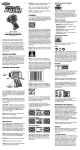
1
Bank: Postbank account: 6084601,
Swiftcode: INGBNL2A
Bank code: NL24PSTB0006084601
Ing. J. de Wijs.
Populierstraat 44,
4131 AR Vianen,
the Netherlands
Tel/Fax. +31 (0)347-372242
e-mail: [email protected]
Website: www.dewijs-3d.com
Tax number: NL 1899.16.084 B01
K.v.K. Reg. Nº 23071201 Utrecht
Design and production of stereoscopic instruments.
User manual for the rotary viewer model 2004
The specification subject to change without prior notices. Last update July 2005
Contents
INTRODUCTION ..................................................................................... 3
1.
1.1
1.2
1.3
2.
2.1
2.2
DIRECTIONS FOR TAKING INTO OPERATION ...................... 4
OPENING THE VIEWER (WITH WOODEN COVER). ................................................... 4
WHERE DO I PLACE THE VIEWER? ..................................................................... 4
HOW CAN I MOUNT THE VIEWER? ...................................................................... 4
MANUAL OPERATION (WITHOUT PC CONTROL)................. 5
INSERTING SLIDES: .......................................................................................... 5
SELECTING FUNCTION MODES ........................................................................... 6
3.
CONNECTION DIAGRAM.............................................................. 7
4.
EXTERNAL CONTROL (WITH PC).............................................. 8
5.
MAINTENANCE ............................................................................... 9
5.1
5.2
5.3
5.4
6.
6.1
6.3
6.4
6.5
6.6
CLEANING SLIDES............................................................................................ 9
CHANGING THE LAMP ...................................................................................... 9
CLEANING / EXCHANGING THE LENSES. ............................................................ 10
SOLVING MISS-ALIGNMENT. ............................................................................ 11
TECHNICAL DATA ....................................................................... 12
SIZES AND DIMENSIONS .................................................................................. 12
CONNECTIONS OF THE D25 AND D15 CONNECTORS. ................................................. 13
CABLING INSIDE THE ROTARY VIEWER.............................................................. 14
ELECTRONIC SCHEMATICS ................................................................................... 15
ELECTRONIC COMPONENT LIST............................................................................. 16
Introduction
This rotary viewer is a result of 30 years experience building public stereo slide viewing equipment.
Every model had its improvements with regards to previous models meaning durability, stability and
quality. This latest model has been build using the latest CAD-CAM techniques and production
techniques. To give an idea of the changes to this model;
- The supporting frame for the drum and lens barrels is now casted, giving more stability and better
alignment of the drum.
- The electronics are now running on 12 Volts dc. For more safety and less dependent on the local
mains voltages using an adapter.
- Illumination by Cold Cathode Fluorescent Lamp (CCFL).
- Improved motor spanner.
- Easier adjustment of misalignment of the drum.
- Easier removal of the front panel from the supporting frame.
- Two choices of appearance; as build-in-wall version and as stand alone with wooden cover
version.
1.
Directions for taking into operation
1.1
Opening the viewer (with wooden cover).
Disconnect all cables from the viewer at the back.
Remove the 2 bolts on top of the viewer mounted in the tilted front panel.
Unlock the lock at the front.
Now grab the lens tubes, pull on these lenses upwards. This should release the mechanical
construction from the cover. Pull the total mechanical construction out of the casing and place it on a
flat solid table. Now you should be able to change slides, remove dust, etc.
1.2
Where do I place the viewer?
Obviously you already have chosen a spot for the viewer in your museum, exhibition or other public
environment. Here are some considerations that might help you to check the spot;
? ? Keep in mind the height of the viewer. Children and grown-ups both want to look in the viewer!
? ? Depending on the interest of the viewer, people might form a queue. This could cause congestion
for the rest of the public.
? ? Watch out for sunlight coming through the lenses! The lenses will act like burn glasses on the
slides. A few minutes in the sun will cause enough damage to the slide that it should be replaced.
Within 1 day, in worst case, you have to replace all slides. You can see this on the slide like tiny
little white spots showing the track of the sun during the day.
? ? Avoid spotlights to be shinning on the lenses. The slides are not going to be burned but it does
shorten the lifecycle of the slide.
? ? Cover the back opening of the viewer with all its connectors and cables. Avoid the public to get
access to this part of the viewer. Let the installation of the electrical cables be executed by
authorised personal only.
? ? Do always provide a grounding facility to the casing of the viewer. By default the Euro connector
provides a solid Earth connection.
? ? When the viewer is to be mounted inside some kind of panel, be sure you can get easy access to
the viewer for replacing the lamp bulb and slides.
1.3
How can I mount the viewer?
? ? The rotary viewer can be used hanging on a wall or mounted on a table. The wooden casing
should be strong enough to hold screws and bolts.
? ? For temporary exhibitions, it is best to place the viewer on a table without any fixation to the
table. Again, when children get access to the viewer, use double-sided tape to fix it to the table.
4
2.
Manual operation (without PC control)
In this situation, the rotary viewer is used in stand-alone mode, without any external control devices.
This mode is also recommended when inserting or changing the slides.
2.1
Inserting slides:
Disconnect all cables from the viewer at the back. Remove the mechanical construction as described
in chapter 1.1.
In the left picture you see how to insert the slides in the drum. With your finger you should keep the
spring on its place when shifting the slide.
After inserting the slide you have to push the slide inside-out of the drum to get it in focus point.
Push with one finger in the middle of the slide frame between the images.
5
2.2
Selecting function modes
The rotary viewer is able to work in 4 different modes, in stand-alone situation. These modes are
configurable using the small switches at the back of the viewer. The black square marks the position
of the switch.
Mode 1:
After the pre-set shut-off time, the lamp turns off and the viewer stays at this
slide.
1 2 3 4
Mode 2:
After the pre-set shut-off time, the lamp turns off and the drum revolves to
slide number 1.
Mode 3:
The lamp is always on, after the shut-off time the viewer stays at the current
slide.
1 2 3 4
1 2 3 4
Mode 4:
The lamp is always on, after the shut-off time the drum revolves to slide
number 1.
1 2 3 4
? ? Connecting the adapter to the corresponding socket can now turn on the rotary viewer.
? ? You can adjust the shut-off time of the lamp by turning with a screwdriver the knob between the
two Sub-D sockets at the rear of the viewer. Turning counter counter-clockwise will increase the
time, turning clockwise will decrease it.
6
3.
Connection diagram
SW1:
adapter:
12 Volts d.c.
1,5A
stabelized
SW2:
SW3:
SW4:
updownupdownupdownupdown-
lamp turn-off delay active
lamp always on
front button passes signal to external device.
front button directly controls viewer
after lamp turns off, nothing happens
after lamp turns off, drum goes to slide Nº 1
amplifier turned off
amplifier turned on
external switch box
Viewer control interface
Lamp turn-off delay
Dutch Enlish German French
Language selection box
Internal CD-ROM in PC
7
4.
External control (with PC)
In this situation, the rotary viewer is able to operate according to a configured
program with or without audible explanation of the slide. An IBM compatible
PC is required to work with the accompanied software of the rotary viewer to
control the rotary viewer. Look at www.dewijs-3d.com at the technical
information and download pages for more information about this function.
8
5.
Maintenance
In general does the rotary viewer not need any mechanical maintenance using it on a fixed
location and handled with care. The viewer is made quite solid with the aim to guarantee the
best optical alignment of the lenses as long as the life cycle of the viewer is. A hard impact at
the front, like tumbling from a table, causes inevitable miss-alignment of the drum and maybe
bend main axle. So be careful when transporting the viewer and arrange a stable spot to place
the viewer. Besides these incidents, the viewer gets covered with a thin layer of dust, outside
as well as inside.
5.1
Cleaning slides.
Open the viewer according to the actions to be taken in chapter 1.1
You have two types of slide mounts;
- mounted in masks and encased in glass.
- mounted in frames without glass
Encased in glass:
In this case you do not have to take the slides out of the drum. Best is to turn the rotary viewer
into manual operation (chapter 2.1 mode 2). Take a soft cloth, clean the slide first at the
outside of the drum. Secondly clean it at the inside of the drum. When cleaning it push it a
little inside out of the drum to preserve fixed focus position of the slide.
Without glass:
This is a difficult situation. Slide frames without glass are very fragile. Taking them out of the
drum, cleaning them, and replace them back again often causes damage to the slide. So if you
can, take a soft brush and wipe the dust away at both sides. When the dust is too much, then
there is no other way than taking them out of the drum. Try cleaning it with the brush and
finally with a soft lens cleaning cloth. Be very careful, some clothes can even scratch the
slides, or decreases the clearness.
5.2
Changing the lamp
The CCFL lamp has a lifespan of 10.000 hours. If the viewer is used 8 hours a day (lamp
turned on) it should take theoretically 3 years before replacing the lamp.
But if the brightness is getting too low follow the next instructions.
? ? Open the viewer according to the actions to
be taken in chapter 1.1
? ? At the left side of the frame you can get
access to the CCFL lamp holder. First
disconnect the cable that runs to the back of
the CCFL panel. Then remove the two bolts
at the left side of the frame that attaches the
lamp to the casted frame.
? ? Now you can take the total CCFL panel with
holder out of the viewer and send it to the
‘de Wijs’company for replacing the lamp.
9
5.3
Cleaning / Exchanging the lenses.
After several years of use the lenses are scratched and dust is coming between the two
achromatic lenses. The lenses are can be taken apart to clean them. Follow the following
steps:
1. Open the viewer according to the actions to be
taken in chapter 1.1
2. The two lens barrels are screwed in the casted
frame and locked with a small M3 bolt on top.
First remove this bolt.
3. The barrels are mounted tight in the frame, use
some kind of ‘belt’spanner to remove the lens
barrels.
4. Now you need to make a small little metal plate
of 1 mm. Thickness. With a length of about 60
mm. And exactly 37 mm. Width.
5. Now put the metal plate in the back off the barrel and be sure it
fits in the small gaps of the screw ring that keeps the lenses in its
barrel as shown in right picture…
6. Turn the metal plate counter clockwise to release the screw.
7. When the screw is released, take a soft cloth and put it with your
finger in the back of the lens barrel against the lenses.
8. Turn the total barrel upside down so the lenses will drop out of the
barrel.
9. Warning!! The lenses do have a front and backside. The
front (view side) is the side with the most flat surface.
This counts for both lenses.
10. With a soft clothe and a brush cleans the lenses. Look
through the lenses against the light to check cleanliness
they might show remaining dust of scratches.
11. If you decide to replace the lenses, you can order them at
the De Wijs Company.
12. Put the lenses together and follow the steps (1-10) in
reverse.
10
5.4
Solving miss-alignment.
Especially during installing the viewer in a public viewing area, parts of the viewer have to be
de-assembled. The drum is the most sensitive part to be aligned for the lenses. The axle on
which the drum is running can be moved to the front or to the back of the viewer. To make
the re-alignment somewhat easier you can check some measurements to get the drum roughly
in position, see the picture below.
The distance from the centre of the axis to the edge of the milled chamber is 20 mm. This
view is seen from the left side of the viewer, that is the side to get access to the CCFL lamp
CAUTION: the optical switches, just above the front plate, close to the push button are fragile
and need to be handled with care when taking the drum out of the frame or moving it into
focus.
11
6.
Technical data
6.1
Sizes and dimensions
Rotary viewer 2004 model A, for 41x101 mm. Frames
? ? Maximum picture format: 28x33 mm.
? ? Lenses: double coated achromatic ø 37 mm. F= 120 mm. (total 60 mm.)
? ? Maximum amount of slides: 21.
? ? Text card size: ??
General data:
? ? Weight rotary viewer, build in wall version: 11.5 kg.
? ? Weight rotary viewer, with wooden cover.
? ? Illumination: Cold Cathode Fluorescent Lamp of 5500 Kelvin
? ? Power supply: 12 Volts. 0,5 Ampère, Adapter 12 Volts stabilized 1,5 Ampère.
? ? Power consumption: 6 Watt.
? ? The rotary viewer is fused for 1 A slow.
? ? D25 connector providing an interface to an XT/AT parallel port of a computer.
? ? D15 connector providing an additional interface to an external language selection device.
? ? The D15 connector is also providing an external stabilised power supply of +5 and +12
Volts.
? ? Adjustment of the turn-off time of the lamp is possible between 5-70 seconds.
? ? The software that is provided with the rotary viewer is written in Pascal 7.0 and runs on
DOS. On almost every x86 machine with CD-ROM player the software will work. A
Windows version will be available in the future.
12
6.3
Connections of the D25 and D15 connectors.
D25 connector:
Connector Description computer side and
pin
addressing
1
Strobe
Base+2 bit 0
2
D0
Base+0 bit 0
3
D1
Base+0 bit 1
4
D2
Base+0 bit 2
5
D3
Base+0 bit 3
6
D4
Base+0 bit 4
7
D5
Base+0 bit 5
8
D6
Base+0 bit 6
9
D7
Base+0 bit 7
10
Acknowledge Base+1 bit 6
11
Busy
Base+1 bit 7
12
Paper end
Base+1 bit 5
13
Select out
Base+1 bit 4
14
Auto feed
Base+2 bit 1
15
Error
Base+1 bit 3
16
Init
Base+2 bit 2
17
Select in
Base+2 bit 3
18
Gnd
19
Gnd
20
Gnd
21
Gnd
22
Gnd
23
Gnd
24
Gnd
25
Chassis
ground
Description rotary viewer
side
Not used
Change slide, 1= moving
Lamp, 1=lamp on.
Not used
Not used
Loopthrough to D15 con.
Loopthrough to D15 con.
Loopthrough to D15 con.
Loopthrough to D15 con.
Button front panel, 1=pressed
Loopthrough to D15 con.
Light gate ‘zero’detection.
Light gate ‘stop’detection.
Not used
Loopthrough to D15 con.
Not used
Not used
D15 Connector: (for language selection box)
Connector Description computer side and Description rotary viewer
pin
addressing
side
1
Busy
Base+1 bit 7
Loopthrough to D25 con.
2
Ground
3
+12 Volt.
4
+5 Volt.
5
D5
Base+0 bit 5
Loopthrough to D25 con.
6
D6
Base+0 bit 6
Loopthrough to D25 con.
7
D7
Base+0 bit 7
Loopthrough to D25 con.
8
Error
Base+1 bit 3
Loopthrough to D25 con.
9
D4
Base+0 bit 4
Loopthrough to D25 con.
10
11
12
13
14
15
Direction looking from
computer side.
Output
Output
Output
Output
Output
Output
Output
Output
Output
Input
Output
Input
Input
Output
Input
Output
Output
Direction looking from
computer side.
Input
Output
Output
Output
Input
Output
13
6.4
Cabling inside the rotary viewer
Optical
switches
Wiring diagram inside rotary viewer
blinking
LED
CCFL tube with diffuser
ccfl inverter
Front
panel
button
Drum
Motor
14
6.5
Electronic schematics
15
6.6
Electronic component list
R1
R2
R3
R4
R5
R6
R7
R8
R9
R10
R11
R12
R13
R14
R15
R16
R17
R18
R19
R20
R21
C1
C2
C3
C4
C5
C6
C7
C8
C9
C10
C11
C12
D1
D2
10K 1/4 Watt IR detect
10K 1/4 Watt IR detect
100K 1/4 Watt
10K 1/4 Watt
100K 1/4 Watt
10K 1/4 Watt
10K 1/4 Watt
100K 1/4 Watt
180 1/4 Watt
100 1/4 Watt
100K 1/4 Watt
100K 1/4 Watt
10K 1/4 Watt
10K 1/4 Watt
1M 0.15 Watt 10 mm. standing Pot.
10K 1/4 Watt
100K 1/4 Watt
180 1/4 Watt
100K 1/4 Watt
10K 1/4 Watt
22 1 Watt
47uF 10 Volt axial
100n 50 Volt polyester
4,7uF 50 Volt Elco rad
100n 50 Volt polyester
100n 50 Volt polyester
1000uF 16 Volt Elco rad.
100n 50 Volt polyester
47uF 10 Volt axial
100uF 16 Volt Elco ax.
100n 50 Volt polyester
100n 50 Volt polyester
100n 50 Volt polyester
1N4001
1N4001
D3
T1
T2
T3
T4
T5
U1
U2
U3
U4
1N4001
BC547b
BC547b
BC547b
BC547b
BC547b
4081 Quad And
Relays 2x 12V OMRON G2R-2
LM555 timer IC
Relays 1x 12V OMRON G5V-1
U5
U6
U7
U8
U9
J1
J2
4071 Quad Or
LM7805 1A
4049 Hex inv. Buff.
LM555 timer IC
LM555 timer IC
D25 PCB socket 90º male
Header 8 pins
Header Socket 8 pins
J3
D15 PCB socket 90º male
J5
Header 2 pins
J6
Header 2 pins
Header Socket 2 pins
Shrink contacts for Headers
SW1 Dip switch 4x 90º
3
DIL8 sockets
2
DIL14 sockets
1
DIL16 sockets
F1 Fuse holder internal metal clamps
1
Opto switches 5mm. Gap with PCB
Wiring to opto coupler and front panel
switch 8 leads 74,5 cm. Long
Wiring to CCFL tube lamp 45 cm.
Wiring to motor; single leads 10 cm.
1
04-01-PCB; circuit board
16