1
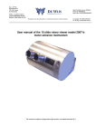
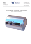
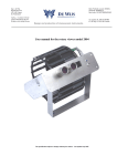
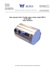
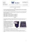
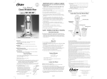
Ing. J. de Wijs.
Populierstraat 44,
4131 AR Vianen,
the Netherlands
Bank: Postbank account: 6084601,
Swiftcode: INGBNL2A
Bank code: NL24PSTB0006084601
Tel/Fax. +31 (0)347-372242
e-mail: [email protected]
Website: www.dewijs-3d.com
Design and production of stereoscopic instruments.
Tax number: NL 1899.16.084 B01
K.v.K. Reg. Nº 23071201 Utrecht
User manual of the 10 slide rotary viewer model 2003
manual advance mechanism
The contents are subject to changes without giving notice. Last update October 2004
Contents
INTRODUCTION ................................................................................... 3
1. FIRST INDICATIONS FOR OPERATIONAL USE .......................... 4
1.1 OPENING THE VIEWER FOR EXCHANGING THE SLIDES. ............................................ 4
1.2 WERE DO I PLACE THE VIEWER?............................................................................ 5
1.3 HOW DO I MOUNT THE VIEWER AGAINST A WALL? ................................................. 5
2. MANUAL OPERATION (WITHOUT PC CONTROL)...................... 6
2.1 TWO OPERATIONAL MODES: .................................................................................. 6
4. EXTERNAL CONTROL (WITH PC) .................................................. 7
4.1 SETTING UP THE EQUIPMENT AND CABLE CONNECTIONS ......................................... 7
6 DATA ...................................................................................................... 8
6.1 TECHNICAL SPECIFICATIONS OF THE ROTARY VIEWER ............................................ 8
6.2 INTERNAL CONNECTION DIAGRAM ......................................................................... 9
6.3 CONNECTIONS OF THE D25 AND J3 CONNECTOR.................................................. 10
6.4 ELECTRONIC COMPONENT LIST MODEL 03-02-A-H .............................................. 11
Introduction
This viewer is the result 30 years of experience in building high quality 3D slide viewers for
public use. Each change in the previous models extended the durability, stability and the
quality. Especially this 10-slide rotary viewer 2003 has been adapted for the demand to
show short 3D slide series to large amounts of public to be informed. To give any idea about
the changes with respect to the previous model:
- The slide drum is available in the motor driven as well as the hand-operated version.
- The viewer can be mounted against a wall and it does not need any cover or housing
to hold the mechanical parts.
- The new CCFL lamp provides a bright cool white light source without any start-up
flickering.
- This viewer is also suited with an automatic return to slide Nº 1 in the motor driven
version.
- External control by means of a Personal Computer is possible.
- A simple 12 Volts dc adapter provides a safe power source.
1. First indications for operational use
1.1 Opening the viewer for exchanging the slides.
- For exchanging the slides you have to remove the
left cover of the round housing; see the image.
That is NOT the side where the text window and
the pushbutton are located.
- Remove the 6 bolts and remove the cover (picture
1)
Picture 1
Picture 2
-
Now you see the round slide drum with a large
nut in the middle, take a bolt spanner, hold the
drum with your hand and remove the nut
(picture 2).
-
Put your hands around the drum and push with
your thumb on the spindle to draw the drum
from the spindle out of the viewer (picture 3).
Picture 4
-
Picture 3
Picture 5
Now you can insert or exchange your slides. Keep the order and position of the
slides in mind that they won’t be presented up side down! (Picture 4 and 5)
After exchanging the slides you can replace the slide drum in the viewer. Be careful
with inserting. Replace the nut on the spindle using the spanner and replace the
cover.
4
1.2 Were do I place the viewer?
Obviously you already have chosen a spot for the viewer in your museum, exhibition or
other public environment. Here are some considerations that might help you to check the
spot;
? ? Keep in mind the height of the viewer. Children and grown-ups both want to look in the
viewer!
? ? Depending on the interest of the viewer, people might form a queue. This could cause
congestion for the rest of the public.
? ? Watch out for sunlight coming through the lenses! The lenses will act like burn glasses
on the slides. A few minutes in the sun will cause enough damage to the slide that it
should be replaced. Within 1 day, in worst case, you have to replace all slides. You can
see this on the slide like tiny little white spots showing the track of the sun during the
day.
? ? Avoid spotlights to be shinning on the lenses. The slides are not going to be burned but
it does shorten the lifecycle of the slide.
? ? When the viewer is to be mounted inside some kind of panel, be sure you can get easy
access to the viewer for replacing the slides.
1.3 How do I mount the viewer against a wall?
The 10 slide rotary viewer holds a bracket at the back that has several holes to attach the
viewer with screws or bolts against a wall. First you have to remove the 3 bolts on the top of
the bracket (see the image) and the bolts underneath the viewer to position the bracket only
against the wall. Think about how you want to let the cables run through the bracket; are
they going through the wall or do they go through the hole at the bottom of the bracket?
5
2. Manual operation (without PC control)
In this situation, the rotary viewer is used in stand-alone mode, without any external
devices.
2.1 Two operational modes:
The rotary viewer is able to work in 2 different modes. These
modes are configurable using the small switches inside the
viewer. To get access to these switches follow the next
directions:
- Removing the 6 bolts of the right cover of the viewer
(the side where the hand wheel is located, picture 6).
Picture 6
Picture 7
-
-
The next step is not easy. Lift the cover just a little bit and
you will see that the power cable is obstructing the cover
to come free.
You can lift the cover a little more and lead the power cord
through the hole at the rear.
Gently take the mechanical interior out of the housing and
take care of the power cord.
Now you see the 4 small switches and the time adjustment for the lamp.
At the right you see an illustration of the dipswitch.
The black square marks the position of the switch.
Mode 1:
After the pre-set shut-off time, the lamp turns off
1 2 3 4
Mode 2:
The lamp is always on
1 2 3 4
-
You can adjust the shut-off time of the lamp by turning with a screwdriver the knob
beside the small switches inside the viewer. Turning counter clockwise will increase the
time, turning anticlockwise will decrease it.
6
4. External control (with PC)
In this situation, the rotary viewer is able to operate according to a
configured program with audible explanation of the slide. An IBM
compatible PC is required to work with the accompanied software of the
rotary viewer to control the rotary viewer.
4.1 Setting up the equipment and cable connections
List of materials:
? ? 10 slide Rotary viewer of ‘de Wijs’model 2003
? ? One 12 Volts dc adapter for the rotary viewer.
? ? Language panel (if you need it).
? ? 1 Euro connector power cables for the computer
? ? 1 parallel extension cable with a male D25 and female D25 plug.
? ? An IBM compatible x86 computer with at least 1 free parallel printer port
connector and CD-ROM player, complete it with the usual keyboard, monitor, etc.
(mouse not necessary)
? ? 3.5”Boot disk for the rotary viewer.
? ? An audio cable with 2,5 mm stereo jack to double cinch or headphones.
Connect all cables according to the connection diagram (chapter 6.2).
Set the small switches at the back of the rotary viewer according to the
picture on the right.
1 2 3 4
For more information about the how to configure the computer and to make audio
tracks, take a look at the software manual that can be downloaded at www.dewijs3d.com at the technical support download page.
7
6 Data
6.1 Technical specifications of the rotary viewer
Slides:
? ? Slide frame format; 41x101 mm.
? ? Maximum picture size; 23x33 mm.
? ? Compatible with RBT frames, mounted between glass maximum 3 mm.
Thickness.
? ? The drum can hold 10 slides and accompanying text cards.
Optics:
??
??
??
??
One lens barrel holds 2 achromatic lenses of ? 37 mm. f= 120 mm. each.
Total focal distance is 60 mm.; magnification: 4.2 x
Lenses are coated on all sides
Lens separation is fixed to 62 mm.
Illumination:
? ? The slide is illuminated by a single CCFL (Cold Cathode Fluorescent Lamp)
passing its light through a light guide.
? ? The colour temperature is 5500 Kelvin.
? ? The lamp runs on 12 Volts dc at ± 300mA using an inverter.
Mechanics;
? ? The Housing of the viewer is made of plain anodised aluminium. The wall
bracket and lens barrels are made of stainless steel.
? ? The slide drum revolves on ball bearings and don’t need any lubrication.
? ? Permanent magnets are providing a feel-able ‘stop’point when turning the
hand wheel. The drum is blocked in reverse direction.
? ? To remove the hand-wheel; hold the internal slide drum and turn the wheel
anti clockwise (left turning thread).
? ? When removing the hand-wheel, you get access to 4 bolts. These bolts make
it possible to adjust the focus of the slide drum with regards to the fixed
lenses. Do NOT un-fasten these bolts, the focus has been adjusted in the
factory very carefully!
Electronics;
? ? The whole viewer runs on 12 Volts dc. The viewer comes with a 220 Volts AC
adapter giving 12 Volts dc. at 500mA.
? ? The internal circuitery is fused with a 1 Amp. fuse.
8
6.2 Internal connection diagram
Dutch Enlish German French
Language
panel
CCFL
lightguide
SW1:
SW2:
SW3:
SW4:
uplamp turn-off delay active
downlamp always on
not used
not used
not used
inverter
SW 1-2-3-4
lamp
turn-off
delay
adapter:
12 Volts d.c.
500 mA
stabelized
IR light positioning switch
9
6.3 Connections of the D25 and J3 connector.
D25 connector:
Connector Description computer side
pin
and addressing
1
Strobe
Base+2 bit 0
2
D0
Base+0 bit 0
3
D1
Base+0 bit 1
4
D2
Base+0 bit 2
5
D3
Base+0 bit 3
6
D4
Base+0 bit 4
7
D5
Base+0 bit 5
8
D6
Base+0 bit 6
9
D7
Base+0 bit 7
10
Acknowle Base+1 bit 6
dge
11
Busy
Base+1 bit 7
12
Paper end Base+1 bit 5
13
Select out Base+1 bit 4
14
Auto feed Base+2 bit 1
15
Error
Base+1 bit 3
16
Init
Base+2 bit 2
17
Select in Base+2 bit 3
18
Gnd
19
Gnd
20
Gnd
21
Gnd
22
Gnd
23
Gnd
24
Gnd
25
Chassis
ground
Description rotary viewer
side
Not used
Change slide, 1= moving
Lamp, 1=lamp on.
Not used
Not used
Loop through to D15 con.
Loop through to D15 con.
Loop through to D15 con.
Loop through to D15 con.
Button front panel,
1=pressed
Loop through to D15 con.
Light gate ‘zero’detection.
Light gate ‘stop’detection.
Not used
Loop through to D15 con.
Not used
Not used
J3 vertical 8-pin header: (for language selection box)
Connector Description computer side Description rotary viewer
pin
and addressing
side
1
Busy
Base+1 bit 7
Loop through to D25 con.
2
Ground
3
+12 Volt.
4
+5 Volt.
5
D5
Base+0 bit 5
Loop through to D25 con.
6
D6
Base+0 bit 6
Loop through to D25 con.
7
D7
Base+0 bit 7
Loop through to D25 con.
8
Error
Base+1 bit 3
Loop through to D25 con.
9
D4
Base+0 bit 4 Loop through to D25 con.
10
11
12
13
14
15
Direction looking from
computer side.
Output
Output
Output
Output
Output
Output
Output
Output
Output
Input
Output
Input
Input
Output
Input
Output
Output
Direction looking from
computer side.
Input
Output
Output
Output
Input
Output
10
6.4 Electronic component list model
03-02-A-H
R1
R2
R3
R4
R5
R6
R7
R8
R9
R10
R11
R12
R13
R14
R15
R16
R17
R18
R19
R20
R21
C1
C2
C3
C4
C5
C6
C7
C8
C9
C10
C11
D1
D2
D3
T1
T2
T3
T4
T5
U1
U2
U3
U4
10K 1/4 Watt IR detect
10K 1/4 Watt IR detect
100K 1/4 Watt
10K 1/4 Watt
100K 1/4 Watt
10K 1/4 Watt
10K 1/4 Watt
100K 1/4 Watt
180 1/4 Watt
Removed in hand wheel configuration.
100K 1/4 Watt
100K 1/4 Watt
10K 1/4 Watt
10K 1/4 Watt
1M 0.15 Watt 10 mm. standing Pot.
10K 1/4 Watt
100K 1/4 Watt
100 1/4 Watt (IR LED’s)
100K 1/4 Watt
10K 1/4 Watt
22 1 Watt
47uF 10 Volt axial
100n 50 Volt polyester
4,7uF 50 Volt axial
100n 50 Volt polyester
100n 50 Volt polyester
1000uF 16 Volt Elco rad.
100n 50 Volt polyest er
47uF 10 Volt axial
100uF 16 Volt Elco ax.
100n 50 Volt polyester
100n 50 Volt polyester
1N4001
1N4001
1N4001
BC547b
BC547b
BC547b
BC547b
BC547b
4081 Quad And
Removed in hand wheel configuration.
LM555 timer IC
Relays 1x 12V OMRON G5V-1
U5
U6
U7
U8
U9
J1
J2
J3
2x
J4
J5
J6
3x
4071 Quad Or
LM7805 1A
4049UBE
LM555 timer IC
LM555 timer IC
D25 PCB socket 90º male
Header vertical 8 pins
Header vertical 8 pins
Header Socket 8 pins
Header vertical 2 pins
Header vertical 2 pins
Header vertical 2 pins
Header Socket 2 pins
Shrink contacts for Headers
J7 Header vertical 3 pins
1x Header Socket 3 pins
SW1 Dip switch 4x 90º
DIL8 sockets
DIL14 sockets
DIL16 sockets
F1 Fuse holder internal metal clamps
2x Opto switches 5mm. Gap
1x PCB of de Wijs company.
11