1
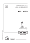
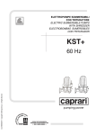
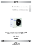
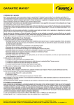
CapSmart-VFD Caprari - Variable Frequency Drive Owner’s manual 240 V~ 50 Hz 240V, 10 Amps WARNING: READ THIS HANDBOOK CAREFULLY BEFORE INSTALLING OR STARTING THE DEVICE. The manufacturer guarantees this product for a period of 24 months as of the date of sale; if returned, the device must be accompanied by this handbook, with the installation date and programming parameter values entered on the last page. The guarantee is forfeited in the event of the following: the device is tampered with, disassembled or damaged due to mishandling and/or incorrect installation; the device is put to any other use than the one it was intended for; the device is installed in unsuitable environmental conditions or connected to a non-standard electrical system. The manufacturer cannot be held responsible for any kind of damage to people and/or things ensuing from failure to install the necessary electrical safety devices upstream of the device, or as a result of unprofessional installation. The installation and servicing of this device must be performed by specially trained personnel with the ability to understand the entire contents of this owner’s manual. For all operations required to be carried out with the cover removed, the device must be disconnected from the power supply. Even though there should not be any reason to remove the card, if you do so, remember that some of its parts remain live for a few minutes after the unit has been disconnected from the mains. The manufacturer cannot be held responsible for any kind of damage to people and/or things ensuing from the failure of any internal safety devices to intervene, with the exception of compensation for the device itself if still under guarantee. This equipment complies with the ROHS 2002/95/EC directive. The symbol of the crossed out bin means that to safeguard the environment the equipment cannot be disposed of with other household waste at the end of its lifecycle. The equipment and packaging must be disposed of according to the local regulations. CONTENTS 2 OVERALL SIZE - DIMENSIONS - IDENTIFICATION………………..………………….22 DESCRIPTION……………………………………………………………………………...…23 SPECIFICATIONS …………………………………………………………………………....23 FEATURES……………..…………………………………………………………………........23 DEVICE PROTECTION FEATURES …………..……………………………………...…...24 INSTALLATION HYDRAULIC CONNECTION ……………………..……………………………………..24 ELECTRICAL CONNECTION …………………………………………………………...25 START-UP…………………………………………………………..……………………….29 PROGRAMMING DESCRIPTION OF THE INTERFACE…………………………………………………...29 DESCRIPTION OF BUTTON FUNCTIONS ……………...……………………………..29 MENU STRUCTURE………………………………………………………….……………30 DESCRIPTION OF THE PARAMETERS AND SCREEN PAGES ….………..……….30 ALARMS………………….……………………………………………………….…………33 POSSIBLE MALFUNCTIONS ……..…………………………...............................................34 MAINTENANCE……………………………………………………………………………….35 3 ↔ OVERALL SIZE - DIMENSIONS -IDENTIFICATION 4 DESCRIPTION CapSmart-VFD is an electronic device, employing inverter-based technology, which controls motor pump, speed, stopping and starting functions. Thanks to the particular type of technology used, it can modulate the frequency (Hz) of the motor’s input current to alter the speed (rpm) according to the water delivery rate required from the system. This way, the value of the pressure reaching the user appliances is maintained constant all the time and the motor's absorption is always proportional to the actual system requirements, resulting in notable energy savings over time. SPECIFICATIONS Power mains supply:…………………….. single-phase, 240Vac -10% + 5% - 50Hz Motor power supply: ………………………three-phase 230V~ Maximum power absorption:………………2200W – 3Hp Maximum motor phase current:……………9.7Arms Max. line absorption:………………….……16A @ 240V~ Max. allowable pressure:…………….…......800 KPa (8 bar) Max. liquid temperature :………………..... 50°C Max. theoretical flow rate:…………………150 l/min – 9m3/h – 9000 l/h Set-point adjustment range:………………..1.5÷7 bar ( 150-700 Kpa ) Start pressure adjustment range:……………1÷ 6.7 bar ( 100-670 Kpa ) Hydraulic connection ………………………BSP ( 32mm ) Frequency modulation range:…………….…25÷50 Hz (30-60Hz optional) Degree of protection :………………… …..IP X5 Weight………………………………………1.6 Kg Dimensions………………………………….254x147x143 mm Type of action...…………………………….1 (according to EN 60730-1) FEATURES √ Constant pressure due to motor pump speed regulation √ Energy savings due to less pump absorption √ Gradual pump start and stop reduces hammering √ Protection against dry running in the event of water shortage during intake √ Automatic reset in the event of dry running, with autonomous error condition recovery √ Efficient leakage monitoring to protect pump in the event of repeated restarts √ Digital pressure display √ Operation/error status signalling via LEDs and on-screen alerts √ Auxiliary contact for remote control, pair connection or double set-point √ Rotation direction inversion via software (does not require wiring alterations) √ Extractable terminals to facilitate wiring √ Possibility of interfacing two devices as part of the pressurisation units 5 DEVICE PROTECTION FEATURES √ Dry running √ Undervoltage on power line (activation at approx. 200 Volt) √ Overvoltage on power line (activation at approx. 260 Volt) √ Output terminal short circuit √ Motor output amperometric control √ Internal overheating in inverter √ Significant leakage with continuous motor pump restarts INSTALLATION HYDRAULIC CONNECTION: Note, If supplied as a CAPRARI Pump System, the following has already been taken care of for you. The CapSmart-VFD must be installed on the pump delivery side, either upright or horizontally and respecting the flow direction shown by the arrow on the cover. The pump outlet water flows through the device before being distributed to the various appliances connected. The water that enters the CapSmart-VFD unit must not contain any impurities and/or other substances that could jam up the check valve fitted inside it. To reduce this risk as much as possible, it is advisable to fit special filters on the intake side of the pump. Install a small expansion tank (1-2 litres) after the CapSmart-VFD, to limit restarts caused by any small leakages which are common in most systems. The pre-charge value of the tank must be suitable for the pressure values set. This will also help to keep the operation constant in applications where water requirements are greater (e.g. for dishwashers, toilet flushing systems, etc.). On no account must a check valve be fitted between the CapSmart-VFD and the motor pump or between the device itself and the user appliances, as it could cause device malfunctions. A check valve can be fitted on the motor pump intake pipe, though, to prevent it draining when the pump stops. It is recommended that you do not install the equipment in shafts or watertight casing where heavy condensation can form. CAUTION: when the pump stops, the conduits are still pressured so a cock must be opened to bleed the system before any work is carried out. 6 ELECTRICAL CONNECTION: Note, If supplied as part of a CAPRARI Pump System, the following has already been taken care of for you. Fit the electric wires into the relative wire clamps, making sure the correct assembly order is maintained for all the components. Secure the threaded nuts tightly enough to prevent the wires being pulled or turned from the outside. The wire clamp for the auxiliary contact is a blind fastener: if you wish to insert a remote control wire, it is best to remove the said nut from the unit, then break open the plastic nut with a screwdriver. If the device is used in one of the following situations: - temperature of the fluid used higher than 30°C - ambient temperature higher than 35°C cables with a thermal resistance of at least 100°C must be used for the power supply and motor cable. MOTOR PUMP CONNECTION CapSmart-VFD can be fitted on three-phase pumps with 240Vac power supply, with a triangular set-up then. This means that the terminals inside the pump must be checked before wiring up the device to ensure they are connected as shown in the figure below: EARTH MOTOR 3X230V~ Before making the electrical connection, the cables must be correctly prepared with the relative terminals to be crimped. Connect the three power wires of the pomp motor to the 3-pole green terminal marked “MOTOR”; then proceed with connection of the earth wire to one of the ends of the double earthing terminal. The terminals must be crimped by specialist personnel, using special pliers for the purpose. This device can run with pumps with a max. rated frequency of 50Hz and a capacity of up to 2200 Watt. The equipment is fitted with an output short circuit protection. The wires have a 1.5 mm2 section and lengths of up to 30 m; for lengths from 30 m to 90 m it is recommended that 2.5 mm2 section wire be used. The type of wire must be selected according to the conditions of use (domestic, dry or wet, indoor or outdoor installation). 7 LINE CONNECTION EARTH The device has a single-phase 240 Volt 50Hz power line. The electrical system to which the equipment is connected must comply with the safety regulations in force and must therefore be equipped with: - an automatic magnetothermal switch with high breaking capacity and with a trigger current proportional to the capacity of the pump installed (see chart below) - earthing with total resistance in conformity with local standards and in any case never over 100Ω. LINE 240V 50Hz If the device is used in swimming pools, fountains or garden ponds, an automatic type “A” residual current operated circuit breaker (with I∆n=30mA) must always be fitted. The system comprising the CapSmart-VFD and a motor pump is considered a “fixed system”; it is therefore advisable to make arrangements to prevent the device being disconnected from the power line it was originally connected to and mistakenly reconnected to another source of power not equipped with the electrical protection required. If the device is not fitted with a power lead and plug, to disconnect it from the mains install an omnipolar cut-off device with a gap of at least 3 mm between the contacts. Before making the electrical connection, the cables must be correctly prepared with the relative terminals to be crimped. Connect the two power wires CAPACITY OF PUMP MAGNETOTHERMAL of the device to the 2-pole green terminal INSTALLED PROTECTION marked "LINE"; then proceed with (KW) (A) connection of the earth wire to one of the 0.37 (0.5 HP) 4 ends of the double earthing terminal. The 0.75 (1 HP) 6 terminals must be crimped by specialist 1.5 (2 HP) 12 personnel, using special pliers for the 2.2 (3 HP) 16 purpose. The recommended wire section is 1.5mm2, which is compatible with motor pumps up to 1.1 kW. For 2 powers over 1.1 kW and up to 2.2 kW a 2.5mm wire section is recommended. If the power lead is longer than 5-10 metres, a lead with a 2.5mm2 section should be used to reduce drops in the power supplied by the lead and to reduce the chance of the under-voltage protection being triggered. The type of wire must be selected according to the conditions of use (domestic, dry or wet, indoor or outdoor installation). All installation restrictions stated by the manufacturer of the motor pump to which the CapSmart-VFD is connected must also be observed. 8 WARNING: - all wiring up must be carried out by specially trained personnel - an incorrect motor pump connection could result in damage to the device or the pump motor. the manufacturer cannot be held responsible for any kind of damage to people and/or things ensuing from failure to comply with the contents of this paragraph. - failure to comply with what is stated in this paragraph may cause serious damage to things and/or serious injuries to people, and the manufacturer declines all responsibility. - if the power supply cable or the cable between the CapSmart-VFD and electropump is damaged, only the manufacturer of the device, its appointee or equally qualified personnel can replace it; this is to prevent risks to things and people. AUXILIARY CONTACT CONNECTION WARNING: the auxiliary contact connector is not extractable! CapSmart-VFD is fitted with a special connector for an auxiliary contact so that additional functions can be exploited by interfacing the device with external equipment. The function of the auxiliary contact depends on the setting of the “Auxiliary Contact” parameter described in the paragraph on programming. The three operational modes, relevant functions and connection methods are described below. AUXILIARY CONTACT CONNECTOR SETTING OF “AUXILIARY CONTACT” PARAMETER = “1” – Exchange function in the pressurisation units. When the “AUXILIARY CONTACT” parameter is set on “1” the CapSmart-VFD is set to work independently (single system) or to dialogue with another partner device as part of a twin pump pressurisation unit, depending on whether the connection cable is used. If the device is set to work independently no connection is required. On the other hand, if the CapSmart-VFD is connected to another unit to create a pressurisation group, follow the wiring diagram shown here; for further information on the operation as part of twin pump pressurisation units see the “PRESSURISATION UNITS” section in the appendix. 9 SETTING OF “AUXILIARY CONTACT” PARAMETER = “2” – Remote on/off control function When the “AUXILIARY CONTACT” parameter is set on “2” the CapSmart-VFD is set to be switched on and off by remote control according to the system EXTERNAL requirements. This function is useful when there is the CONTACT need to programme the start of the motor pump at the same time as other devices connected to one same control unit, for example in irrigation systems where the pump is switched on only when the irrigation control unit activates one or more of the system’s solenoid valves. Connect the device according to the wiring diagram shown here, bearing in mind that when the external contact is open the CapSmart-VFD shall not start the pump even if the system reaches the Pmin value, while when the external contact is closed the device shall operate according to the values set. SETTING OF “AUXILIARY CONTACT” PARAMETER = “3” – Second set-point (Pmax2) function When the “AUXILIARY CONTACT” parameter is EXTERNAL set on “3” the CapSmart-VFD is set to adjust the CONTACT rotations of the motor pump in accordance to the Pmax2 pressure value. This function is useful when the device must temporarily work at a different pressure to the one set in the Pmax parameter, for example if distributors requiring different pressures are used. Connect the device according to the wiring diagram shown here bearing in mind that when the external contact is open the CapSmart-VFD shall adjust the pump rotations according to the Pmax pressure value , while when the external contact is closed the device shall adjust the pump speed according to the Pmax2 value. ATTENTION: incorrect wiring of the auxiliary contact may cause the low voltage circuit to short circuit with consequent blowing of the fuse! Carry out the connection with particular care. 10 START-UP: WARNING: do not allow the pump to run for long without water the first time it is switched on otherwise the inverter will overheat! Prime the pump before switching on the system. Once all the electrical connections have been made and checked to ensure they are correct, close the unit’s cover and switch on the power. The CapSmart-VFD is now in stand-by; in this mode (pump stationary) all the various parameters can be set (see “programming” paragraph) before the system is started up. To start up the pump, simply press the “on-off” button in the centre: The CapSmart-VFD will quit the stand-by mode and the motor will start turning. Check that the motor pump is rotating in the right direction; if it is not, the motor phases can be inverted using the software (see “programming” paragraph) without needing to open the cover again. To facilitate pump filling, the “+” button on the main screen can be pressed to force the pump up to top speed without the dry running protection feature cutting in. After setting all the device parameters, write the data entered in the form found at the end of this handbook for future reference and for guarantee purposes. PROGRAMMING: DESCRIPTION OF THE INTERFACE 1 Note: If the device has been supplied as a part of a CAPRARI System and your operations parameter have been provided at the time of ordering, these values will have be pre set for you. As confirmation this5 values will be hand written in the back of this manual. 1. Digital display, showing pressure, errors and configuration menus. 4 3 2. Motor pump start, stop and programming buttons. 3. Green warning light to signal line is live (LINE) 4. Red warning light to signal error conditions (FAILURE) 5. Yellow warning light to signal pump operation (PUMP ON) DESCRIPTION OF THE BUTTONS 2 Left-hand arrow: this scrolls back through the menu pages Right-hand arrow: this scrolls forwards through the menu pages On-Off/Reset: this switches the device from stand-by to operation mode and resets the unit in the event of alarms and/or errors. “+” button: this increases the value of the parameter currently shown on the display, it allows the pump to run at top speed under forced operation. “ “-” button: this decreases the value of the parameter currently shown on the display; it displays the instantaneous current absorbed by the motor. 11 MENU STRUCTURE DESCRIPTION OF THE PARAMETERS AND SCREEN PAGES USER PARAMETERS: These parameters are accessible when the device is on. Main screen page: when the CapSmart-VFD is in the standard operation mode, the first line on the display shows the instant pressure reading; the second line contains a bar chart showing the motor speed as a percentage. In this mode, the user can scroll through the various menus using the cursor buttons, or switch to stand-by by pressing the “on-off” button in the centre. When the CapSmart-VFD is in stand-by, the pump will not start up even if the pressure drops below the “Pmin” value set. To quit stand-by, press the button in the centre again. If the “+” button is held down, the pump is brought up to the maximum operating speed, overriding the dry running protection (use this function to fill the pump the first time it is switched on). Press the “-“ button to display the absorption of the motor. Pmax: this parameter can be used to set the device set-point. This is the constant pressure value the user wishes to set for the system (max. pressure). When it is operating, the CapSmart-VFD regulates the motor pump speed to suit it to the actual output required by the user appliances, thereby keeping the system pressure constant. If the Pmax is set to higher than the max. pump head, the motor will always stop when the cocks are closed as the CapSmart-VFD switches off the pump when the flow rate of the water running through it drops below the minimum settings (approx. 2 litres/minute), regardless of the pressure reached in the system. Use the + and – buttons to alter the parameter setting. 12 Pmax2: this page is only displayed if the “AUXILIARY CONTACT ” parameter is set on “3” (second set-point function); this parameter is used to set the secondary set-point of the device. When the auxiliary contact is externally closed the Pmax2 pressure value becomes the new set-point according to which the CapSmart-VFD adjusts the speed of the motor pump. Pmin: this value represents the pump restart pressure. When any user appliance is switched on, the pump does not start up until the system pressure has dropped below the Pmin value. Once the motor has started running, its rotation speed is regulated to keep the pressure as near as possible to the value set for the Pmax. The minimum differential settable between Pmax and Pmin is 0.3 bar, although it is advisable to keep it at least 0.5 bar. Use the + and – buttons to alter the parameter setting. Stop delay: Use this parameter to define after how many seconds the motor pump should stop once all the functions have been closed. If when the flows are low the pump continuously switches on and off, increase the switching off delay so that the operation is smoother. Increasing the parameter can also be useful to stop the frequent triggering of the dry run protection device especially in submersed pumps or pumps that have self-priming problems. The default value set by the manufacturer is 10 seconds. Use the “+” and “-“ to change the stop delay value. Auto-reset interval: if the pump experiences a temporary shortage of intake water while it is operating, the CapSmart-VFD cuts off the power to the motor to prevent it being damaged. From this screen page, a device automatic restart time can be set (in minutes) at the end of which a test will be run to see if the intake water supply has returned. If the test is successful, the CapSmart-VFD automatically quits the error status and the system becomes operative once again; if it fails, another attempt will be made after the same amount of time has lapsed. The maximum interval allowed is 300 minutes (recommended value: 60 min). Use the + and – buttons to alter the parameter setting. Auto-reset test n.: this parameter sets the number of attempts that the CapSmart-VFD will make to resolve a stop condition due to dry running. Once this limit has been exceeded, the system shuts down and the user’s intervention is required. If this value is set to zero, the auto-reset function is switched off. The maximum number of attempts allowed is 10. Use the + and – buttons to alter the parameter setting.. Maximum number of starts in an hour: From this page you can set the maximum number of starts of the motor pump in one hour before the intervention of the Serious Leakage alarm. Only short starts are counted, in other words those which are not followed by the suction of minimum 2.5 litres/min of water. If the Serious Leakage alarm is activated too often or without reason, then it is advisable to increase the parameter on this page using the “+” button. If on the other hand you wish to completely deactivate the leakage control, then press the “-“ button until the word “OFF” appears on the bottom line of this page. 13 Language: The language used for the menus and the alarm messages can be selected by the user. Use the + and – buttons to alter the parameter setting. INSTALLER PARAMETERS: These parameters can be found on hidden pages and usually they should only be changed in the installation phase. To access these pages switch the device to Stand-by and keep the “+” and “-“ buttons pressed down together for 5 seconds. Once you have entered the hidden menu, use the “<<” and “>>” buttons to scroll the pages and the “+” and “-“ buttons to change the parameters. To return to the main page press the button in the centre. Rotation direction: The direction of rotation of the motor pump can be inverted from this page without having to change the wiring of the electric motor. To change the direction of rotation of the motor use the “+” and ““ buttons; the direction shown by the arrow is merely indicative and does not represent the actual direction of rotation which must in any case be checked by the installer. PID Control: This parameter is used to set the speed of reaction of the system to changes in pressure (accelerations and decelerations). Low PID values represent a slow but more accurate reaction (more gradual start and stop) while the higher values of this parameter can be used for a higher reaction speed. When the system is unstable (pressure oscillations with consequent changes in the speed of the motor) it is advisable to set the lower PID values. On the other hand, when the system's reaction to pressure variations is too slow we recommend increasing the PID value (max. 50). The default value set by the manufacturer is 25. Use the “+” and “-“ buttons to change the values of the PID parameter. Minimum frequency: Use this parameter to set the minimum frequency of the motor pump power supply (i.e. the number of rotations). The value is expressed as percentage of the maximum frequency value. The parameter can be set at the following values: 50, 60 or 70%. For surface pumps a 50% minimum frequency is recommended as set by the manufacturer, for pumps submersed up to a depth of 8-10 metres a 60% value is recommended, for pumps submersed over 10 metres the parameter should be set at 70%. In any case, it is useful to increase this parameter when the start-up of the motor pump is too slow and there is a significant loss of pressure in the system during this phase. Use the “+” and “-“ buttons to change the minimum frequency values. Imax: this parameter is used to set the maximum current that must be absorbed by the motor pump in ordinary conditions, so that the motor will stop in case of excessive absorption. The motor shall stop also if the current measured during operation is lower than 0.5 A following the interruption of the connection between the motor and the CapSmart-VFD. The intervention time of the protection in case of excessive absorption is inversely proportional to the overload, therefore a slight overload shall trigger longer intervention times while a great overload will lead to a rapid interruption. The parameter can be set at a value between 0.5 a 9.7 A. When the device is switched on if the Imax parameter is set at 0.5 A (manufacturer’s default setting), the page from which to set the maximum current value will be displayed; no action can be carried out until the maximum absorption value has been set. 14 Auxiliary contact: use this parameter to select the function to be associated with the auxiliary contact; the values that can be set are the following: “1 <->” to use the auxiliary contact to connect two CapSmart-VFD devices as part of a twin pressurisation unit (manufacturer’s default setting) “2 <-“ to use the auxiliary contact to remote control the start stop of the motor pump. “3 X2” to use the auxiliary contact to control a second pressure set-point (Pmax2). Further information on the wiring and on the three different operational modes is contained in the “AUXILIARY CONTACT CONNECTION” section. ALARMS Dry running: this message appears when the system is stopped following a pump intake water shortage. If the auto-reset function has been enabled, the CapSmart-VFD will automatically make a series of attempts to test whether the water supply has returned. To clear the error status, press the “reset” button in the centre. Serious leakage: this message appears when the pump has been stopped following a closely spaced series of restarts caused by a possible leak in the system. To restore the system status once the cause of the alarm has been established, press the “reset” button in the centre. If this condition occurs repeatedly, impairing normal pump operation, this feature can be disabled. Before disabling, though, ensure it will not cause damage to the pump or system (see section titled “DESCRIPTION OF THE PARAMETERS AND THE SCREEN PAGES”). Inverter error: this alarm appears when the inverter is locked following a power surge or drop outside the limits or overheating with ensuing motor pump shutdown. Although the system is restored automatically approx. 3 minutes after the error condition has cleared, the message remains on the screen to warn the user that there might be a failure in the hydraulic and/or electric system. Every time this alarm appears, it is advisable to have the system checked by skilled personnel to prevent electrical damage. To clear the message from the display, simply press the “reset” button in the centre. Short Circuit: This message will appear on the screen when there is a short circuit at the inverter output. the short circuit may be caused by the incorrect connection of the electric motor, faulty electrical isolation of the cables that connect the motor pump to the devices or failure of the electric motor of the pump. When this error appears, the electrical system must be controlled by qualified personnel as soon as possible. The error can only be cleared by disconnecting the device from the electric power supply and solving the causes of the fault. Attempting to start the inverter when there is an output short circuit may seriously damage the device and be dangerous for the user. Overload: This alarm appears when the absorption of the motor pump is greater than the maximum current value set (Imax); this may be caused by extremely difficult working conditions for the motor pump, problems related to the motor winding , if the pump is restarted continuously at 15 short intervals or following problems with the wiring of the motor to the CapSmart-VFD. If this alarm is often displayed the system should be checked by the installer. POSSIBLE MALFUNCTIONS: When one of the valves in the system is opened, the pump does not start, or there is a few seconds delay before it starts The Pmin is set too low or a check valve has been fitted downstream of the device. Try increasing the start pressure Pmin and remove all check valves fitted downstream of the CapSmart-VFD. When the valves are closed, the pump stops but restarts a few seconds later and there is no leakage from the system The difference between the Pmin and the Pmax is too low and the drop in pressure that occurs when the pump stops is sufficient to make it restart. Increase the Pmax value or decrease the Pmin. The pump keeps switching on and off There is leakage in the system. Check the various hydraulic connections. Check the display for pressure drops when the valve is closed. Check the CapSmart-VFD's check valve for dirt which could be preventing it from closing properly and, if necessary, clean it with compressed air. The device often signals 'dry running' The pump intake pipe drains when the system is not used for some time, thereby preventing it priming the next time it is started. If there is a foot valve fitted, check its seal. The device frequently signals an inverter error. The supply voltage may not comply with the equipment specifications; the control must be carried out by qualified personnel. The inverter no longer exchanges heat with the water that runs through the device or the temperature of the fluid pumped is too high; check for foreign bodies that block the flow of water and if necessary have the device checked by the manufacturer. When the water flow is extremely low, the pump does not operate normally. The flow values are too low and as the device is unable to detect them, it shuts down the motor pump. Fit a small surge tank (1-2 litres) in the system to give it more flexibility and reduce the number of restarts. The pump does not stop There is substantial leakage in the system or the check valve on the device is jammed by dirt; try moving the check valve with your fingers and checking that the spring can maintain the seal. The sensor which detects the valve position is broken. Have the device checked by the manufacturer. The pump is running at top speed but performance levels are low The pump might be running backwards. Try inverting the rotation direction. The pump is damaged or there is foreign matter clogging the waterway. 16 When more water is required of the system, the pressure drops This is a normal condition which is due to the fact that the device is unable to force the pump above its capacity curve. As a result, once a certain capacity is reached, the pressure is no longer offset as the pump is already running at the highest number of revolutions allowed. In these cases, a pump with higher performance levels should be installed. The “Inverter error” message often appears on the display a few seconds after the motor pump is started The error may be caused by a non-compliant power voltage. With the pump running, use a suitable gauge to measure the voltage at the power terminals and determine whether the problem concerns underpowering or overpowering. If it is the former, use a power lead with a larger section to reduce voltage drops, but if it is the latter, contact the manufacturer. 17 MAINTENANCE: The CapSmart-VFD is designed to keep maintenance requirements at a minimum. To guarantee the device a long working life and perfect functionality, always follow the instructions below: Place your CapSmart inside a pump cover or shelter, do not expose it to the wheather and direct elements. - ensure the device does not have to withstand temperatures of below 3° C; if this is not possible, make sure all the water inside it is drained out to prevent it from freezing up and damaging the device’s plastic body; - if the pump is equipped with intake filters, carry out regular checks to ensure they are clean; - make sure the cover is always properly closed to prevent water leaking in from outside; - switch off the power supply and drain the water from the system when it is going to be left unused for some time; - do not force the pump to run without intake water, as this could damage both the pump and the CapSmart-VFD; - before using the device with any other liquids than water, contact the manufacturer. - do not carry out any operations when the device is open - wait 3 minutes before removing the cover from the device so the condensers can discharge. WARNING: this device does not contain any parts that can be repaired or replaced by the end user. You are therefore advised not to remove the electronic card's protective cover as this would lead to forfeiture of the guarantee! Installation date …./…./……. Fitter Customer Pump make/model CapSmart-VFD serial n. VALUES SET AT INSTALLATION Pmax Bar Pmax2 Bar Pmin Bar Stop delay Seconds Auto-reset time Minutes Auto-reset test Test n. Start/hour max NO YES ( n° max start:_________) Rotation direction PID Minimum frequency 50% 60% 70% Imax Ampere Auxiliary contact 1 2 3 Notes 18 Installation and connection in twin booster sets NOTE: for CAPRARI “Multi-Cap” – Cvx System. INSTALLATION: install each CapSmart-VFD unit on the pressure line of the corresponding electric pump. Connect the outlet union of each inverter to the delivery manifold without interposing a check valve. Connect the suction of the electric pumps to the common intake manifold, interposing a check valve for each pump to prevent it from emptying when stopped. CapSmart-VFD is compatible with both vertical and horizontal installation. CONNECTION: the two CapSmart-VFD units are connected by an unshielded 4x0.5 mm2 cable as shown in the diagram beside. The maximum cable length is 100 cm including stripped ends. Customers can order a preassembled connection cable with terminals and cable numbering - Ref. SR-CBL4X05-100. If no cable is connected the device will function in stand-alone mode. MASTER STATUS: when the device works as a MASTER it is sensitive to pressure changes in the plant and thus capable of starting and stopping the pump unit and modulating pump rpm in accordance with water demands from the plant. SLAVE STATUS: when the device works as a SLAVE two capital S characters appear on the display bottom line; in this condition if the pump is running the speed remains constant, while if the pump is stopped its starting is inhibited even when the taps are opened. OPERATION: at the time of power-on the first device that gets the control over the other becomes the MASTER while the other functions as the SLAVE. When user services are opened the MASTER device starts the pump and when the maximum rotation speed is reached and the system pressure is lower than the preset Pmin value, it transfers control to the second inverter, which becomes the new MASTER, while the first inverter becomes the SLAVE and its rotation speed remains fixed. With the progressive closing of the user services the second device stops the pump and control is again transferred to the first inverter, which will stop the electric pump when the water demand is reduced to zero after complete closing of each user. After the electric pump has been stopped MASTER status is again transferred to the other device to ensure constant changeover of the pump that is started first. In the event of a fault or error on one of the two inverters, the healthy device will automatically assume MASTER status and start operating in stand-alone mode. To activate the changeover function it is not necessary to set any parameters in the menu because CapSmart-VFD automatically detects the presence of a secondary device once the electrical connection has been made. The Pmin and Pmax values set must be the same for both devices. 19 CE DECLARATION OF CONFORMITY IT - Con la presente si dichiara che la macchina qui di seguito indicata, in base alla sua concezione, al tipo di costruzione e nella versione da noi introdotta sul mercato, è conforme ai requisiti fondamentali di sicurezza e di sanità delle direttive CE. In caso di modifiche apportate alla macchina senza il nostro consenso, la presente dichiarazione perde ogni validità. RUS – Настоящим заявляется, что оборудование, указанное в руководстве, а именно: его оригинальный дизайн, тип конструкции и модель, выпущенная для продажи; - соответствует основным нормам техники безопасности и не представляет угрозу здоровью согласно директив СЕ. В случае каких-либо изменений оборудования, которые несанкционированны с изготовителем, данная декларация будет признана недействительной. FR - Nous déclarons par la présente que la machine indiquée ci-dessous, telle qu’elle a été conçue, construite et commercialisée par notre entreprise, est conforme aux exigences fondamentales de sécurité et de santé des directives CE. En cas de modifications apportées à la machine sans notre accord, la présente déclaration n’a plus aucune validité. ES - Con la presente se declara que la máquina mencionada a continuación, según su diseño, tipo de fabricación y en la versión comercializada, responde a los requerimientos fundamentales de seguridad y de sanidad de las directivas CE. En caso de modificaciones hechas a la máquina sin nuestra autorización, esta declaración pierde su validez. DE - Hiermit erklären wir, dass die wie folgt genannte Maschine aufgrund ihres Konzepts, der Bauart und der von uns auf den Markt eingeführten Ausführung den grundsätzlichen Anforderungen bezüglich der Sicherheit und der Gesundheit der EG-Richtlinien entspricht. Falls die Maschine ohne unsere Zustimmung geändert wird, verliert diese Erklärung jegliche Gültigkeit. MODEL: CapSmart-VFD TYPE: SR23251-XX-XXX DIRETTIVA: DIRECTIVE: DIRECTIF : DIRECTIVA: RICHTLINIEN: 2006/95/EC LVD 2004/108/EC EMC CON RIFERIMENTO A: WITH REFERENCE TO: CONCERNANT: REFERENTE A: MIT BEZUG AUF: EN 60730-1:2002 ANNO MARCHIATURA: MARKING YEAR: ANNÉE D'INSCRIPTION: AÑO DE LA MARCA: MARKIERUNGS-JAHR: 08 EN 61000-6-4:2007 EN 61000-6-2:2006 08 Tribano, 29 July 2008 Mr. Demetrio Bertazzo For: CAPRARI Pumps Australia Pty Ltd 3 Jeanes street Beverley SA 5009 Ph: +61 8 82444442 Fax: +61 8 82444462 Web: www.caprari.com 20 ______________________________________ ______________________________________ ______________________________________ ______________________________________ ______________________________________ ______________________________________ ______________________________________ ______________________________________ ______________________________________ ______________________________________ ______________________________________ ______________________________________ ______________________________________ ______________________________________ ______________________________________ ______________________________________ ______________________________________ ______________________________________ ______________________________________ ______________________________________ ______________________________________ ______________________________________ ______________________________________ ______________________________________ ______________________________________ ______________________________________ 21 Caprari Pumps Australia, 3 Jeanes St Beverley South Australia Tel. +61 8 8244 4442 Fax. +61 8 8244 4462 www.caprari.com 22