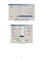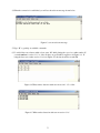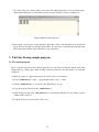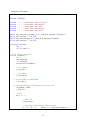
1
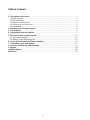
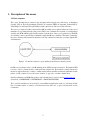
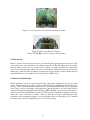
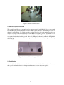
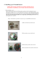
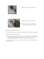
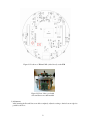
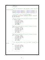
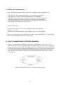
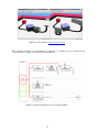
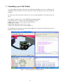
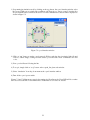
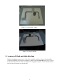
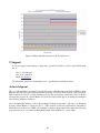
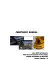
e-puck Ground Sensors
User’s Manual
(Version 21NOV07)
AAI Canada, Inc.
Ottawa, Canada
Table of Contents
1. Description of the sensor .......................................................................................................... 3
1.1 Basic structure ........................................................................................................................ 3
1.2 Line following ........................................................................................................................ 4
1.3 Surface or fall detection.......................................................................................................... 4
1.4 Surface gray-level detection ................................................................................................... 5
1.5 Localization ............................................................................................................................ 5
2. Installing e-puck Ground Sensors............................................................................................ 6
3. Test Program ............................................................................................................................. 9
4. Adjusting the detected position................................................................................................ 9
5. The Line Tracing sample program ........................................................................................ 12
5.1 The sample program ............................................................................................................ 12
5.2 Making a Line Following track ........................................................................................... 15
6. e-puck Ground Sensors in Webots simulator........................................................................ 15
7. Controlling e-puck with Webots............................................................................................. 17
8. Accuracy of black and white detection.................................................................................. 19
9. Support...................................................................................................................................... 20
Acknowledgment.......................................................................................................................... 20
References ..................................................................................................................................... 21
1. Description of the sensor
1.1 Basic structure
The e-puck Ground Sensors extension was designed and developed at the Laboratory of Intelligent
Systems (LIS) at École Polytechnique Fédérale de Lausanne (EPFL) in Lausanne, Switzerland by
Adam Klaptocz and Jean-Christophe Zufferey under supervision of Professor Dario Floreano.
The sensor is comprised of three active infrared (IR) proximity sensors placed in the front of the e-puck
miniature robot pointing directly at the ground. These sensor elements are mounted on a small printed
circuit board (PCB) which is placed in the vertical slot at the front of the e-puck’s plastic base. The PCB
also includes a microcontroller that continually samples the IR sensor elements. The values obtained by
the sensor elements and formatted by the microcontroller can then be read by the e-puck through the I2C
serial interface.
Figure 1.1 Connection between e-puck and the Ground Sensors extension board
One IR sensor element consists of an IR-emitting diode (LED) and a phototransistor. The infrared LED
is used to emit a constant amount of infrared beam, whereas the phototransistor simply detects the
amount of signal reflected by a surface. A white surface reflects much more infrared signal than a black
surface, as will a surface closer to the sensor element, as opposed to one that is farther away.
Detailed schematics and PCB Gerber files for the Ground Sensors can be found at www.e-puck.org.
(Download -> HARDWARE -> EXTENSIONS -> GROUND SENSORS)
The e-puck Ground Sensors can be used for several different applications such as 1) following a black
line on a white surface, 2) surface or fall detection below the robot, 3) gray scale detection, and 4)
localization.
Figure 1.2 A close-up view of the e-puck Ground Sensors module
Figure 1.3 Three active IR sensor elements,
Vishay’s TCNT1000 are spaced out along a horizontal line
1.2 Line tracing
Because of their location near the front of the e-puck and the lateral spacing between the 3 sensors, they
can be easily used to trace a black line on an otherwise white surface. The line simply needs to be smaller
than the distance between the two external sensors (12mm). A simple algorithm can command the
motors in a way that keeps the middle sensor above the black line, while the external sensors detect the
white space to either side. This algorithm is currently being used in a student exercise in the Bio-Inspired
Adaptive Machines course taught by Prof. Dario Floreano at EPFL [1] [2].
1.3 Surface or fall detection
The Ground Sensors can also be used to detect the edge of the surface on which the e-puck is run, such as
a table. The ground below the edge of a table top reflects much less light than the table directly below
the robot. This is especially useful in case there are no solid boundaries defining the robot’s experiment
arena. Figure 1.4 shows an example of this application of the Ground Sensors as used by Chris Cianci’s
experiment at the Swarm-Intelligent Systems Group of EPFL. Multiple e-pucks are run on the surface of
a table for specific swarm intelligence research [3]. The four edges of the table are marked by black tape
which tells e-puck a boundary is reached. Since no walls are involved in delineating the arena,
experiments can be run without having to be concerned with reflection of IR signals e-puck’s standard
proximity sensors emit, thus simplifying e-puck’s on board processing.
Figure 1.4 Surface or fall detection
1.4 Surface gray-level detection
The e-puck Ground Sensors is currently used for a student exercise in the Mobile Robots course taught
by Jean-Christophe Zufferey and Dario Floreano at EPFL [4], as a device to differentiate gray levels on
an arena’s surface (Figure 1.5). In this case, the e-puck moves along a bar code and the ground sensors
are used as an input to the measurement model in a Markov localization process. Very similar sensors
are00. used many times in the field of Evolutionary Robotics by Prof. Floreano. Black or gray areas
were painted on an otherwise white ground. The robot (a Khepera at the time) could easily distinguish in
which region of the environment it was, using the intensity value returned by the ground detecting
sensors [5] [6].
Figure 1.5 Arena used for surface gray-level detection
1.5 Localization
A series of black and white patterns can be drawn on the surface of the robot’s experimental arena so
that e-puck’s on-board software can interpret such patterns to localize its present position.
2. Installing e-puck Ground Sensors
Caution: The warranty is void if the e-puck and/or associated parts are
disassembled, or modified by user in a manner other than shown below.
1) Disassemble the e-puck
Remove the battery from the bottom. Dismount the extension board from the plastic body, as
described below. Make sure not to remove the wheels from the motor axles during installation of the
Ground Sensors. In case you do remove the wheels, pay extra attention when replacing and tightening
the wheels. The built-in link gears in the motors are very fragile, and they may break if tightened too
much. When fastening the wheels with the nuts, use light torque, while making sure it is not too loose,
allowing the motor to spin free.
<Steps to dismount the top extension board, and e-puck’s main PCB from the chassis>
Remove the battery from the bottom.
Unscrew three screws circled in red.
Dismount the speaker extension board.
Unscrew the three hex standoffs circled in red.
Remove plastic ring from the plastic body
Dismount the PCB from the plastic body
Remove the motor connector from JM1
(large red rectangle in Figure 2.1 in Page 8)
2) Installation of the Ground Sensors module
Connect the connector for Ground Sensors module at JB0 (small red oval in Figure 2.1 in Page 8).
Re-connect the motor connector at JM1.
Insert the Ground Sensors module in the vertical slot at the front of the e-puck’s plastic base.
When installing the module, make sure the face of the 3 active IR sensor elements points
downward and the module’s CPU is mounted to face outward as shown in Figure 2.2.
Use tweezers if necessary and extra care when working with the connectors of the Ground Sensors
module and the motor.
Figure 2.1 Positions of JB0 and JM1 (circled in red) on the PCB
Figure 2.2 Front of the e-puck with
a Ground Sensors module installed
3) Adjustment:
After inserting the Ground Sensors module completely, adjust its seating so that its bottom edge sits
parallel to the floor.
4) Reassembly:
After the adjustment, put everything back together.
3. Test Program
Test program, “advance_sercom” will enable you to read the detected values from the sensor elements
of Ground Sensors.
1) Download the e-puck-svn-snapshot from
http://www.e-puck.org/index.php?option=com_remository&Itemid=71&func=select&id=7
If above link does not work, go to www.e-puck.org, then DOWNLOAD
SOFTWARE
LIBRARY
2) Unzip and load sercom.hex onto the e-puck
3) Download TeraTerm (free of charge) from http://ttssh2.sourceforge.jp/ or HyperTerminal (payment
required) from http://www.hilgraeve.com/htpe/index.html and load it onto your PC which has a
Bluetooth function. If you are using Windows 95/NT4.0/98/98 SE/ME, Windows 2000 or XP,
HyperTerminal program is included as part of the operating system.
4. Adjusting the detected position
To determine the best position of the reflective active IR sensor elements, we describe the procedure
using Tera Term as an example.
1) Turn on your e-puck, and start TeraTerm on your PC. Make sure to register your e-puck as a
Bluetooth detection tool on your PC before starting.
2) On the ‘New connection’ screen, choose ‘Serial’ and the COM port number e-puck assigns. Click
‘OK’. Verify if the orange LED of the e-puck turns on.
3) Click ‘Setup’ from the menu bar, and then ‘Serial port’. Confirm that the settings are the same as
shown below. Click ‘OK’.
Figure 4.1 New connection with Tera Term
Figure 4.2 Serial port setup
4) When the connection is established, you will see the welcome message shown below.
Figure 4.3 sercom welcome message
5) Type “H” to get help on available commands.
6) To verify if the sensor detects white colour, enter “M” while placing the e-puck on a white surface. If
your sercom.hex is version 1.1.5 or older, all data you get should be negative as in Figure 4.4. If
using the latest sercom.hex version 1.1.6 as in Figure 4.5, the data should be around 950.
Figure 4.4 White surface detection with sercom version 1.1.5 or older
Figure 4.5 White surface detection with sercom version 1.1.6
7) To verify if the sensor detects black colour, enter “M” while placing the e-puck on a black surface.
Printed black-ink may not be detectable. All data you get should be positive as in Figure 4.6.
Figure 4.6 Black surface detection
8) If the values you get are not as they should be, adjust the position of the Ground Sensors module and
repeat the above test until you get appropriate values. It is necessary to maintain approximately 1mm
between the object and the sensor elements for proper detection.
5. The Line Tracing sample program
5.1 The sample program
By choosing the trace-line mode in the program, the robot can follow a black line drawn on the white
background (e.g., white paper), while avoiding obstacles found in its way and return to its track after
disruption.
A sample program for a simple line tracing is shown below for your reference.
1) Create “runlinetracer.c” in the “...\program\demo\demo_swis_1” folder.
2) Add the “runlinetracer.c” you created to the “DemoSwis1” project
3) Copy the program code below into “runlinetracer.c”
4) Add CALL processing of the “run_linetracer()” to the branch method process according to selector
number in the “main_c.c”
5) Compile above project, and load it to the e-puck
<runlinetracer.c Program>
’
5.2 Making a track for line tracing
Draw a black line on the white surface. Some tips for making the track are described below.
a) If using paper, white slick paper suitable for colour printing is recommended.
b) If using a pen to draw lines, black permanent marker is recommended.
c) Black lines printed in grayscale on plain papers may not be detectable by the sensor.
d) If using a printer, high resolution colour print on slick paper is recommended.
e) Avoid over printing on the same paper because it may cause printers to malfunction.
f) The thickness of the line must be about 18 mm.
When the track is ready,
1) Set the rotary switch of your e-puck to the number assigned for the line trace.
2) Turn on your e-puck.
3) Place your e-puck on the black line, and it should be able to follow the black line.
If it does not operate well, set the acceptance value ‘100’ to smaller than 100 in the “1_buffer[*]>100”
line to detect and determine black colour of the program.
6. e-puck Ground Sensors in Webots simulator
Webots is a standard 3D robot simulator developed by Dr. Olivier Michel of Cyberbotics S.à r.l
(www.cyberbotics.com). The e-puck_line controller program contains the source code for a simple line
tracing system which, as an exercise, can be improved upon to obtain the behavior demonstrated in the
e-puck_line_demo.wbt demo. In this demo the simulated e-puck robot is able to follow a black line, but
also to leave the line if it encounters an obstacle placed on the line it is tracing. The e-puck would
wall-follow the obstacle until it circumvents it and reaches the line on the other side of the obstacle.
(See Figure 6.1).
Figure 6.1 Trace-line and Follow-obstacle modes in the program
Figure 6.2 3D simulation (www.cyberbotics.com)
The controller in Webots uses Subsumption Architecture to simulate the above mentioned line
following behavior. Figure 6.3 shows the software structure.
Figure 6.3 Software architecture for following line (EPFL)
7. Controlling e-puck with Webots
e-puck has a Bluetooth interface allowing it to communicate with Webots. In order to use Bluetooth to
communicate remotely with a real e-puck, make sure you have already paired your e-puck with your
computer.
To run the above line-follow demo remotely on a real e-puck through Webots, follow the steps shown
below.
1) Load the bootloader to the e-puck using ICD2 programmer/debugger.
2) Load firmware 1.1.5 or later to the e-puck using tiny bootloader.
3) Place your e-puck on a surface with a line and obstacle(s).
4) Turn on your e-puck.
5) Run Webots application version 5.1.13 or later
6) Open e-puck_line_demo.wbt as shown in Figure 7.1.
Once the Bluetooth connection is properly setup, the Bluetooth connection must appear in the second
popup menu of the control window.
Figure 7.1 Line following demo running in Webots
1) Stop running in simulation mode by clicking on the stop button. On e-puck interface window select
the correct COM port associated with your Bluetooth. Then choose “remote control” from the first
drop down menu. Once connected, the version of serial communication software will be displayed as
shown in Figure 7.2.
Figure 7.2 e-puck interface window
2) Click on “run” button to run the e-puck remotely. Webots reads the data (proximity, light, Ground
Sensors, camera image) coming from the actual e-puck and sends motor commands to the real
robot.
3) Your e-puck will start following the line
4) To stop it, simply click on “stop” button on the e-puck_line_demo.wbt window.
5) Select “simulation” from drop down menu at the e-puck interface window.
6) Turn off the e-puck power switch.
Figures 7.3 and 7.4 illustrate an e-puck robot running in follow-line mode. Front LED will be on when
the robot follows the line. A side LED will be on when the robot follows an obstacle.
Figure 7.3 e-puck follows obstacle
Figure 7.4 e-puck follows line
8. Accuracy of black and white detection
With the sercom.hex program version 1.1.5 or later, e-puck Ground Sensors detects black and white
colour very accurately as shown below in Figure 8.1. Please note that sercom.hex version 1.1.5 is used
for this test and the values for white colour detection in the graph are negative. Accurate detection makes
line following performance smooth and stable.
Figure 8.1 Black and white detection by the Ground Sensors
9. Support
If you need support in introducing or using AAI’s e-puck Ground Sensors, please contact AAI Canada,
Inc. at:
Tel: + 1 613 839 6161
Fax: +1 613 839 6616
Email: [email protected]
We will answer questions concerning the sensor’s specifications, installation, and use.
Acknowledgment
The e-puck Ground Sensors was developed at the Laboratory of Intelligent Systems (LIS) of EPFL by Adam
Klaptocz and Jean-Christophe Zufferey under the leadership of Professor Dario Floreano, http://lis.epfl.ch.
They contributed to Section 1 of this document as well as the development of the initial version of the line
following list program. Dr. Olivier Michel of Cyberbotics SA provided support in running and testing the
line following simulation in Webots.
Drs. Jean-Christophe Zufferey of École Polytechnique Fédérale de Lausanne’s Laboratory of Intelligent
Systems, Olivier Michel of Cyberbotics S.à r.l. , Gilles Caprari of GCtronic, and Francesco Mondada of
Mobile Robotics Laboratory of EPFL, all contributed to improve this document. The sample line following
program shown in 5.1 was written by Masayuki Karasaki of Kodai HiTec Co., Ltd. in Japan.
References
[1]
[2]
[3]
[4]
[5]
Bio-Inspired Adaptive Machines course at EPFL: http://moodle.epfl.ch/course/view.php?id=216
Line following exercice at EPFL: http://moodle.epfl.ch/mod/resource/view.php?id=13709
Chris Cianci’s home page at EPFL: http://www5.epfl.ch/swis/page1339.html
Mobile Robots course at EPFL: http://moodle.epfl.ch/course/view.php?id=261
Floreano, D. and Mondada, F. (1996) Evolution of Homing Navigation in a Real Mobile Robot. IEEE
Transactions on Systems, Man, and Cybernetics--Part B: Cybernetics, 26(3), 396-407.
[6] Floreano, D. and Urzelai, J. (2000) Evolutionary Robots with on-line self-organization and behavioral
fitness. Neural Networks, 13, 431-443.