1
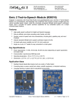
NIK HEF
NATIONAL INSTITUTE FOR NUCLEAR AND HIGH ENERGY PHYSICS
ETR XX
ALCAPONE0/1 control chip
TECHNICAL DOCUMENT
LHC / ALICE / Inner Tracker System / Silicon Strip Detector /
EndCap modules
31 March 2003
Project no: 43000
Ruud Kluit, Jan David Schipper, Vladimir
Gromov, Paul Timmer
email: [email protected]
[email protected] (logic)
[email protected] (supply)
[email protected] (LVDS)
Abstract:
This control chip is designed to control the detector front-end electronics on the hybrids
connected to the double-sided Silicon Strip Detectors. The electronics at both sides of the
detector module operate at different bias potentials. The main functions are power
regulation and signal distribution (buffering). The chip itself is programmable via the IEEE
1149.1 (JTAG Boundary Scan Test) protocol.
The ALCAPONE has integrated features to be able to use AC-coupled signal transfer in
order to cross the bias potentials.
The chip is designed in a 0.25µm CMOS process. By using “gate-around” layout
techniques, the chip is radiation tolerant.
NIKHEF, DEPARTMENT OF
ELECTRONIC TECHNOLOGY
P.O.box 41882, NL 1009 DB AMSTERDAM
ALICE/ITS/SSD/EndCapModules
NIKHEF Amsterdam.R.Kluit,
8-7-2003
Contents
Contents ......................................................................................................................................................... 2
List of figures:................................................................................................................................................ 3
Changes in ALCAPONE1 ................................................................................................................................. 3
1
Introduction ........................................................................................................................................... 4
2
Functional description .......................................................................................................................... 4
2.1
LVDS and CMOS buffers/repeaters ........................................................................................... 4
2.1.1
Low Power LVDS AC input.............................................................................................. 5
2.1.2
LVDS driver with disable function.................................................................................... 5
2.1.3
CMOS AC input ................................................................................................................ 5
2.1.4
CMOS output..................................................................................................................... 5
2.2
Readout and Token (delays) ........................................................................................................ 5
2.3
Power regulator ............................................................................................................................ 6
2.3.1
Shunt regulator................................................................................................................... 6
2.3.2
Power supply regulator ...................................................................................................... 7
2.4
Adc ................................................................................................................................................. 8
2.5
Error Handling ............................................................................................................................. 8
2.6
JTAG logic....................................................................................................................................... 8
2.6.1
Instruction register ............................................................................................................. 9
2.6.2
IdCode................................................................................................................................ 9
2.6.3
Bypass................................................................................................................................ 9
2.6.4
Extest ................................................................................................................................. 9
2.6.5
INTEST .............................................................................................................................. 10
2.6.6
SAMPLE/PRELOAD ............................................................................................................ 11
2.6.7
ENDCAPSTATUS................................................................................................................ 11
2.6.8
POWERCONTROL .............................................................................................................. 12
2.6.9
DELAYCONTROL .............................................................................................................. 12
2.6.10
CHIPCOUNT ...................................................................................................................... 13
2.6.11
POWERREFERENCE ........................................................................................................... 13
2.6.12
ADC .................................................................................................................................. 13
2.6.13
ADCINPUT ........................................................................................................................ 13
2.6.14
ERRORMASK .................................................................................................................... 13
2.6.15
RESET ............................................................................................................................... 14
2.7
3
ALCAPONE
ALCAPONE
reset functions .......................................................................................................... 14
Pin descriptions.................................................................................................................. 15
3.1
LVDS receivers & drivers pins for AC coupling ..................................................................... 15
3.2
JTAG signal pins ........................................................................................................................ 15
3.3
Power supply pins....................................................................................................................... 15
3.4
Miscellaneous pins ...................................................................................................................... 16
3.5
Test Pads (internal pads in chip area) ...................................................................................... 16
3.6
Specials ........................................................................................................................................ 16
3.6.1
ALCAPONE0: ..................................................................................................................... 16
3.6.2
ALCAPONE1: ..................................................................................................................... 17
4
Connections by functional position in EndCap:................................................................................. 18
2of 28
ALICE/ITS/SSD/EndCapModules
NIKHEF Amsterdam.R.Kluit,
8-7-2003
5
Bugs: .................................................................................................................................................... 19
6
ALCAPONE
Test description ................................................................................................................. 20
6.1
Supply & Shunt test: .................................................................................................................. 20
1. De ‘Shuntregulator’. ..................................................................................................................... 20
6.1.1
2. De 1.25V referentiespanning. (RefOut). ...................................................................... 20
6.1.2
3. De ‘Supplyregulator’. .................................................................................................. 21
6.2
Test time calculation................................................................................................................... 24
7
References: .......................................................................................................................................... 24
8
Appendix .............................................................................................................................................. 24
ALCAPONE1
ALCAPONE0
ALCAPONE0
ALCAPONE0
ALCAPONE1
top schematic............................................................................................................................. 25
bond diagram in PLCC84 ......................................................................................................... 26
Pads and probe numbers ........................................................................................................... 27
layout......................................................................................................................................... 28
layout......................................................................................................................................... 28
List of figures:
Figure 1 ALCAPONE1 schematic symbol_____________________________________________________ 4
Figure 2 LVDS receiver for AC-coupling diagram ____________________________________________ 5
Figure 3 Timing diagram of the token readout _______________________________________________ 6
Figure 4 Token readout scheme. __________________________________________________________ 6
Figure 5 External Power supply components ________________________________________________ 7
Figure 6 ADC block diagram _____________________________________________________________ 8
Figure 7 ALCAPONE1 pins ______________________________________________________________ 17
Figure 9 Adc input range ______________________________________________________________ 19
Figure 10 testschema voor 1. en 2. _______________________________________________________ 20
Figure 11 testschema voor 3A, C en D ____________________________________________________ 21
Figure 12 testschema voor 3 B. __________________________________________________________ 22
Figure 13 testschema voor E. en F. en G. __________________________________________________ 23
Changes in ALCAPONE1
In the ALCAPONE1, ADC ‘TestMode’ is added. ................................................................................................ 8
In the ALCAPONE1, the Status [1] bit is Power status, and Status [0] is the Error sum. ................................. 9
ALCAPONE1: Version number = 0001. ............................................................................................................ 9
In ALCAPONE1, one Input pin is added, LVDS_CMOS.................................................................................. 10
In ALCAPONE0, the DAC bits are inverted. This is solved in ALCAPONE1. ..................................................... 11
In ALCAPONE1, the ENDCAPSTATUS register has 4 additional bits:................................................................ 11
In ALCAPONE1, two bits are added to the POWERCONTROL register. ............................................................. 12
In ALCAPONE1, one bit is added in the DELAYCONTROL register. .................................................................. 12
In ALCAPONE1, the ADC value is correct. ..................................................................................................... 13
In ALCAPONE1, the ADC input selection is correct. ...................................................................................... 13
In ALCAPONE1, all error status bits are active ‘1’. The mask bits are ‘1’ when masked............................... 13
In ALCAPONE1, the JTAG chain remains closed when the RESET instruction is selected. ............................. 14
In ALCAPONE1, the ADC logic is reset by _ResetAC. .................................................................................... 14
In ALCAPONE1, the JTAG LVDS/CMOS input selection is made with the LVDS_CMOS input. ..................... 17
3of 28
ALICE/ITS/SSD/EndCapModules
NIKHEF Amsterdam.R.Kluit,
8-7-2003
1 Introduction
This ASIC (Application Specific Integrated Circuit) is designed to control
the Front-end chips on the detector hybrids of the ALICE Silicon Strip
Detector Inner Tracker and is called ALCAPONE, “ALice Control And
POwer NExus”. The front-end chip is the HAL25 [1], designed by
LEPSI/IRES in Strasbourg.
This chip requires JTAG control signals for the adjustment of internal registers (e.g. bias). In addition timed signals for sample/hold and the readout
are required.
These signals must be distributed through the system (End Cap Module
[2]), and therefore locally buffered. In addition, local control and monitor
functions close to the front-end are required. This includes a power regulator and ADC for monitoring. Error checking and failure “recovery” functions are also required.
Figure 1 ALCAPONE1 schematic symbol
2 Functional description
The ALCAPONE design contains a number of functional blocks:
• LVDS and CMOS buffers/repeaters with AC coupled inputs
• Front-End readout token control
• Power regulator with Latch-up protection and (shunt) regulator for local power
• ADC for monitoring functions
These blocks will be described separately. The Logic and de ADC share the same Power input (Vdd). The
(shunt-) regulator for local power and the Power regulator have each a separate power input on the
ALCAPONE. A system overview is described in “Design of ladder EndCap electronics” [2].
2.1
LVDS and CMOS buffers/repeaters
A number of signals are just feed through the ALCAPONE chip. These are Clk, Hold, FastClr and Test.
These signals are received via a Low Power LVDS receiver with positive feedback for AC coupling. The
Fast clear (FastClr) signal is also used internal to reset the front-end readout control. This clears the readout
cycle during readout.
The Token output can be delayed from the input. This depends to which side of the detector module the
token must be sent. The delay is programmable via the JTAG bus.
The 10MHz CLK that must be distributed inside the ECM use LVDS signals. The JTAG signals to the ECM
are using LVDS levels, but once received they are distributed with CMOS levels inside the ECM and to the
front-end modules. Look in the ALCAPONE Pin descriptions to find which signals are only buffered.
4of 28
ALICE/ITS/SSD/EndCapModules
NIKHEF Amsterdam.R.Kluit,
8-7-2003
2.1.1
Low Power LVDS AC input
These LVDS receivers have been optimized to work with 10MHz signals
(tested up to 50MHz) and have low
power consumption (~550uA) [3]. The
circuit is also provided with a disable
control input. In the situation where the
receiver is not needed, it will be disabled to save power.
The receiver is supplied with a positive
feedback circuit (level adapter in
Figure 2) and has a hysteresis of
±25mV.
Figure 2 LVDS receiver for AC-coupling diagram
This feedback circuit delivers the DC levels of correct LVDS (~0.9 & 1.3V) to the receiver input (via a
high impedance circuit) to ensure that the receiver works well when the inputs are AC coupled with 47pF
capacitors. A reset signal ensures that the total circuit can be reset to the required initial state. This is necessary when AC-coupled signals are used, after power is switched on.
2.1.2
LVDS driver with disable function
Once the signals are received, they are directly connected to LVDS output drivers. These drivers are modified drivers from the cmos6sf25PadLib from RAL/CERN. The drivers deliver ~3.6mA through 100Ω. The
modification is that a disable function is added, where the outputs become high impedant when the circuit
is disabled. This is necessary for the Latch-up protection method, when the power for the hybrids is
switched off, no current should flow through the signal connections.
2.1.3
CMOS AC input
The CMOS input circuit is basically a standard cell from the cmos6sf25Pad library. The difference is a
positive feedback via a ±50kΩ resistor. This is necessary to receive AC coupled signals. In addition, a
RESET function is added to determine the initial state after the power is switched on. Low active inputs are
RESET to ‘High’. Since these circuits do not dissipate power when they are not used, there is no disable
function.
2.1.4
CMOS output
The buffered CMOS outputs are slightly modified. A disable function is added in such a way that the outputs have high impedance when the drivers are disabled. This is for the Latch-up protection.
Most outputs can drive 8mA and some have slew rate limited output stages. Outputs that have to drive
more inputs have a 20mA output drive capability.
2.2
Readout and Token (delays)
The readout control for the front-end chip, the HAL25, is done using 4 signals:
• The HOLD, this signal activates the sampling of the input amplifier value of the HAL25 (sample
and hold).
This signal only needs to be buffered. It is not used inside the ALCAPONE
• The CLK activates the logic for the readout. It is only available during the readout cycle. The
ALCAPONE requires 4 CLK cycles before TokenIn, and 4 cycles after the ReturnToken.
The CLK signal is buffered by the ALCAPONE, and used to generate the delayed token signal.
• This is followed by a Token; this signal determines when a specific data sample is multiplexed to
the output of the HAL25 chip. The Token is sent first to one side of the detector module, and delayed to the second side of the module.
The ALCAPONE generates the delay based on a fixed number of CLK cycles, dependant of the
number of HAL25 chips to be read out. This number is programmable.
• To clear an on going readout cycle the FastClear signal must be activated (low active).
This signal is used by the ALCAPONE to clear the internal token readout sequence.
5of 28
ALICE/ITS/SSD/EndCapModules
•
NIKHEF Amsterdam.R.Kluit,
8-7-2003
The Test signal is used to simulate a hit in the analogue front-end of the HAL25. The Hold signal
must be delayed from ‘Test’ according to the programmed shaper time of the HAL25 chip.
This signal only needs to be buffered. It is not used inside the ALCAPONE
The CLK, HOLD and FastClear signals can be
sent to both sides of a detector module hybrid at
the same time. However, to make sure that the
two sides are readout sequentially, the token is
first sent to one side. A delayed (delay as long as
one module readout) token is sent to the other
module side. The delay can be programmed in
steps of 128 CLK cycles, from 0 to 6 steps
(maximum number of chips on a hybrid.) Once a
hybrid is completely readout, it returns the token
(TokenCheck). This is checked by the
ALCAPONE. An internal delay is used to synchronize the hybrid return token with the internal
token.
Token (1) input
BufferEnable
(1) output
Token (2) input
Token (3) input
Token (3) output
P-side
SelectSwitch (3)
output P-side
TokenCheck (3)
Input P-side
Token (3) output
N-side
SelectSwitch (3)
output N-side
TokenCheck (3)
Input N-side
Figure 3 Timing diagram of the token readout
The token signal is sampled by the CLK at the rising edge, and the token output is released when the CLK
goes low. If the returned token does not appear at the right moment in the ALCAPONE, an error will be generated. Errors are described later in chapter “Error Handling”, page 8.
The readout signals in the EndCap are visualized in Figure 3 and Figure 4. First, the signals are received in
the ALCAPONE (1) at GND level. Then they are
sent to each detector side and there again buffered
Maxim al 7
Detectors.
by (2). Then the signals reach the ALCAPONE (3)
that is connected to the hybrids with the HAL25
Alcap one
Alcap one
Alcap one
(1)
(2)
(3)
chips. In these chips, the delay must be generated,
6 x HAL25
such that each detector side of a module is readout
P -sid e
sequentially. This chip also controls the analogue
Alabuf
Analog
Output
multiplexer in the ALABUF chip (SelectSwitch).
The corresponding analogue channel is activated
during readout.
N-sid e
Gnd
The first ALCAPONE in the ECM will switch on the
Alcap one
Alcap one
6 x HAL25
(2)
(3)
analogue buffer chip as soon as the token is received. The signal BufEnable, is active during the
Maxim al 7
programmed CHIPCOUNT + the ReadoutTime time
Detectors.
values.
Toke n
Toke n
To ke n
To ke n
B uffer
Ena bl e
Sel ec t Swit ch
An al og
o ut
Sel ec t Swit ch
To ke n
An al og
out
To ke n
Toke n
Figure 4 Token readout scheme.
The FastClear signal will RESET the delays, but nothing else. A readout cycle can be aborted, and after release of the signal, the chip is ready to start a new readout cycle.
2.3
Power regulator
A Power supply regulator in the chip is necessary to create latch-up protection for the electronics succeeding the ALCAPONE chips. This power “block” consists of two parts, the shunt regulator and the power supply regulator.
2.3.1
Shunt regulator
This circuit is used to generate the correct supply voltage for the power regulator circuit. It consists of a
Bandgap reference with buffer and a shunt regulator circuit. This whole circuit can be supplied from a 3 to
6Volt power supply (via a 180Ω resistor) and it delivers always 2.5V for the power regulator circuit.
Specifications:
Value
Tolerance
VshuntRef
2.52V
30 mV
Max. Shunt current
XxxmA
1mA
6of 28
ALICE/ITS/SSD/EndCapModules
Min. Shunt current
NIKHEF Amsterdam.R.Kluit,
8-7-2003
XxxmA
1mA
2.3.2
Power supply regulator
The regulator is able to regulate the power for 1 to 15 ALCAPONE chips, or for a HAL25 hybrid. This corresponds to ±150mA and ±1A. The circuit is controlled via JTAG and an
external signal SuppOn. This signal determines if the regulator should
switch on after the power is switched on, or not. In this always on mode,
the shunt regulator must power the power supply circuit.
Again, a Bandgap reference circuit is used to generate a reference voltage
for the regulator. To adjust the output voltage, an 8-bit DAC is impleCurrent Detect
mented to modify the reference for the output voltage
Measure
The regulator is switched off when the output current exceeds a limit.
Output
This limit is determined by the value of the current sense resistor, R14 in
Figure 5. When the voltage over this resistor exceeds 19mV (±0.1V), the
power is switched off. It can be switched on again via JTAG, or in case,
that SuppOn is “high”, by switching off and on the external voltage.
Figure 5 External Power supply components
During the power-up of the power supply of the ALCAPONE chip, the following sequence occurs:
1. Until the input power voltage reaches “Vin min.”, the start-up circuit will keep the output off.
2. After this, the Bandgap reference becomes stable, the output is switched on to “Vout-min.”, and
the POnRESET is held active by the start-up circuit. During this time, the over-current protection is
disabled and capacitive load can be charged.
3. The ALCAPONE is now switched on (Power DAC=0~2V), and after POnRESET is finished the default value for the power-DAC is loaded, and the output goes to about 2.5V.
4. Now the regulator circuit is in normal operating mode and sensing the output current. The powerDAC value can be modified via the JTAG port.
In ALCAPONE1, every time a change is made to the DAC value, the over-current protection is disabled
for about 30µs. This is done to prevent the power to be switched off due to an over-current of charging load
capacitors.
Specifications:
Value
Tolerance
Vin min
2.1V
200mV
Vin max.
2.7V
10mV
Vout min.
1.9V
100mV
Vout max.
2.9V
100mV
Vout default
2.52V
100mV
Vdropout min
300mV
50mV
Over current timer
34µs
10µs
Startup timer
320µs
50µs
Switch sense limit
19mV
0.5mV
Change timer
30µs
5us
7of 28
ALICE/ITS/SSD/EndCapModules
NIKHEF Amsterdam.R.Kluit,
8-7-2003
switch
inputs
2.4
Adc
For monitoring purposed is an 8-bit successive approximation ADC (Figure 6) implemented in the chip. The
input multiplexer has 4 inputs. This is followed by a sample and hold circuit. This is a “switch” and a 2pF
capacitor with a buffer. The voltage has the ALCAPONE “gnd” input as ground reference. The ADC logic is
clocked from an oscillator that needs an external
Reset
RC network (10k & 10nF for ~30kHz). Instead, a
defined clock can be connected to the “OscIn”
Testmode
Clock A
osc.
input.
Hold
B
The conversion time is the clock period multiplied
B
A
by 20. From this clock, two non-overlapping sigsample
comparator
B
nals are generated to operate the switches.
SAR
DataOut
The SAR logic determines the correct DAC value
logic
that corresponds with the input voltage. The
A
8-bit
‘Hold’ signal is to prevent the result register to be
Vref
DAC
read and written at the same time, the read action
is blocked.
Figure 6 ADC block diagram
Specifications:
Range min
Range max
Linearity error
Current out
Value
0V
2V
1%
9.96µA
Tolerance
+50mV
50mV
.5 %
.1µA
Input 3 is provided with a current source output of 10µA. This can be to connect a NTC of 100k to monitor
the temperature.
In the ALCAPONE1, ADC ‘TestMode’ is added.
In ‘TestMode, the DAC value is counting from 255 to 0 continuously and the resulting voltage can be verified at one of the selected analog inputs (not 3). In normal operation, the ADC continuously digitizes the
selected input, and the result can be read out via JTAG. The analogue range is from 0 to 2 Volts (0-255).
2.5
Error Handling
Some error situations can be monitored and flagged
• Supply switched off due to over current:
PowerStatusLatch is ‘1’ if the error has occurred. PowerStatus is ‘1’ if the error is still there.
• Return token from hybrid is not received:
TokenError is ‘1’ if a token did not return at the expected moment.
• Parity of all control registers is changed (bit flip due to radiation).
All bits in POWERCONTROL, DELAYCONTROL, CHIPCOUNT, POWERREF, and ERRORMASK are
used in the parity check. If a bit flips during normal operation, (e.g. due to radiation) it is detected.
• External error from detector P- or N side received:
If one of both inputs recognizes an error, the ErrP/Nside bit is ‘1’. The ErrN/P side bit represents
that an error has been detected.
If one of these errors is recognized, it will be flagged. The flag must be RESET manually via the status register with bit ResetControl. All flags are now cleared.
JTAG logic
2.6
Via this logic, all ALCAPONE functions can be controlled. The logic consists of a TAP state machine with
the mandatory IEEE 1049 JTAG registers and functions. Extra registers have been added for control functions of the chip. If “IEEE JTAG” is mentioned in the table header, the instruction behaves according to the
IEEE 1049.1 standard.
The JTAG communication can occur via CMOS- or LVDS signals. The LVDS signals are used if the
ALCAPONE receives the signals over a long distance and the CMOS signals inside the ALICE EndCap module and to the hybrid. Via the LVDS_CMOS input, the selection is made (see chapter Specials, 3.6)
8of 28
ALICE/ITS/SSD/EndCapModules
NIKHEF Amsterdam.R.Kluit,
8-7-2003
2.6.1
Instruction register
The JTAG instruction register has four bits that are decoded to the following instructions:
1. Extest
0000
0001
2. SAMPLE/PRELOAD
3. IdCode
0010
0011
4. INTEST
5. ENDCAPSTATUS
0100
6. POWERCONTROL
0101
7. DELAYCONTROL
0110
8. CHIPCOUNT
0111
9. POWERREFERENCE
1000
10. ADC
1001
11. ADCINPUT
1010
12. ERRORMASK
1011
1100
13. RESET
14. Bypass
1111
The Instructions go together with data registers, although INTEST, EXTEST and SAMPLE/PRELOAD share the
one Boundary-Scantest register.
The input and output cells, which have a BST register can be found in page 15, ALCAPONE Pin descriptions
BYPASS and RESET have a register of 0 (zero) length.
Reading the instruction register will result in: [status1, status0, 0, 1]. The status bits are defined as ‘0’.
In the ALCAPONE1, the Status1 bit is Power status, and Status0 is the Error sum.
2.6.2
IdCode
This register holds a pRESET number this is 1000000001, and can only be read.
IDCODE
0010
IEEE JTAG
Bits [1:0]
01
R
Bits [5:2]
Version Number [3:0],
R
0000, 0001
Bits [9:6]
Chip ID [3:0], 0001
R
A RESET of the JTAG logic will set the IDCODE instruction in the instruction register. Therefore, after
RESET, (or Power On) the IDCODE can be read out and the JTAG chain can be determined.
ALCAPONE1: Version number = 0001.
2.6.3
Bypass
The BYPASS Instruction is a mandatory JTAG instruction and has no real register. The instruction puts the
chip in a transparent mode for JTAG communication.
BYPASS
1111
IEEE JTAG
2.6.4
Extest
This Instruction is used to test interconnections between chips. It puts all output cells in active mode and
the EXTEST register content is placed in the BST cells to the output drivers. The situation of the input cells
is sampled in to the EXTEST register and can be read out.
EXTEST
0000
IEEE JTAG
Bit [1:0]
01
R
Bit [2] ALCAPONE1
LVDS_CMOS in
R
Bit [2], [3]
Clk out
R/W
Bit [3], [4]
Hold out
R/W
Bit [4], [5]
FastClear out
R/W
Bit [5], [6]
Test out
R/W
Bit [6], [7]
Token out
R/W
Bit [7], [8]
TokenCh in
R/W
Bit [8], [9]
ErrNside in
R/W
9of 28
ALICE/ITS/SSD/EndCapModules
NIKHEF Amsterdam.R.Kluit,
8-7-2003
Bit [9], [10]
ErrPside in
R/W
Bit [10], [11]
SelectSwitch out
R/W
Bit [11], [12]
BufEnable out
R/W
Bit [12], [13]
_POnRESET out
R
Bit [13], [14]
SuppOn in
R/W
Bit [14], [15]
_RESETAC in
R
Bit [15], [16]
Error CMOS out
R/W
Bit [16], [17]
Error LVDS out
R/W
Bit [17], [18]
Token in
R/W
Bit [18], [19]
Test in
R/W
Bit [19], [20]
FastClear in
R/W
Bit [20], [21]
Hold in
R/W
Bit [21], [22]
Clk in
R/W
The EXTEXT register bit _PonRESET is made read-only, this is because in some positions of the
ALCAPONE0 on the ECM, the _POnRESET is connected to _RESETAC. An EXTEST write would cause an
error in this situation
In ALCAPONE1, one Input pin is added, LVDS_CMOS.
This pin is the first pin in the list, so it becomes Bit [2]. All other Bits shift one position. This is in the INTEST, EXTEST and SAMPLE/PRELOAD register If it is ‘1’ the LVDS JTAG inputs are used, else the CMOS.
2.6.5
INTEST
With this instruction, internal functions can be tested. In the ALCAPONE0, the direct connections between
the input and output can be checked.
In addition, the token delay can be checked. By asserting a token, followed by enough TCK clock cycles
according to the programmed delay, the TokenOut is latched internal. The latched token can be read out via
the INTEST instruction and asserting a FastClr signal via the same register can clear the latched token. In
this way, the various delay settings can be tested via JTAG. In addition, the activation of BufEnable and
SelectSwitch can be checked this way.
IEEE JTAG
INTEST
0011
Bit [1:0]
01
R
Bit [2] ALCAPONE1
LVDS_CMOS in
R
Bit [2], [3]
Clk out
R
Bit [3], [4]
Hold out
R
Bit [4], [5]
FastClear out
R
Bit [5], [6]
Test out
R
Bit [6], [7]
Token out
R
Bit [7], [8]
TokenCh in
R/W
Bit [8], [9]
ErrNside in
R/W
Bit [9], [10]
ErrPside in
R/W
Bit [10], [11]
SelectSwitch out
R
Bit [11], [12]
BufEnable out
R
Bit [12], [13]
_POnRESET out
R
Bit [13], [14]
SuppOn in
R/W
Bit [14], [15]
_RESETAC in
R
Bit [15], [16]
Error CMOS out
R
Bit [16], [17]
Error LVDS out
R
Bit [17], [18]
Token in
R/W
Bit [18], [19]
Test in
R/W
Bit [19], [20]
FastClear in
R/W
Bit [20], [21]
Hold in
R/W
Bit [21], [22]
Clk in
R/W
No INTEST function can be performed with the _ResetAC pin. This would cause an error.
10of 28
ALICE/ITS/SSD/EndCapModules
NIKHEF Amsterdam.R.Kluit,
8-7-2003
2.6.6
SAMPLE/PRELOAD
This register is used to sample the present input or output state of the I/O cells to which the BST registers
are connected. The PRELOAD is used to set the registers before an INTEST instruction. Therefore, the content of this register is the same as the INTEST register.
2.6.7
ENDCAPSTATUS
The actual chip status can be checked.
ENDCAPSTATUS
0100
Bit [1:0]
Bit [2]
Bit [3]
Bit [4]
Bit [5]
Bit [6]
Bit [7]
Bit [8]
Bit [9]
Bit [10]
Bit [18:11]
Bit [22:19]
Bit [25:23]
Bit [28:26]
Bit [29]
Bit [30]
Bit [31]
Bit [32]
Bit [33]
Bit [34]
Bit [35]
Bit [36]
Bit [37]
1
Control Read, default
Control Write
01
PowerOn, 0
PowerStatus, 0
PowerStatusLatch, 0
SuppOn, ext.1
PowerMask, 1
DelayOn, 0
TokenError, 0
TokenERRORMASK, 1
HALTestMode, 0
DAC [7:0], 95hex
ADC_Input [3:0], 0
WaitTime [2:0], 6
ReadoutTime [2:0], 6
_ErrPside, 0
ErrPsideLatched, 0
P_Mask, 1
_ErrNside, 0
ErrNsideLatched, 0
N_Mask, 1
ParityError, 0
ParityErrorLatched, 0
ParityERRORMASK, 1
X
ResetLatches
HALTestMode
X
X
X
X
X
X
X
X
X
X
X
X
X
X
X
X
X
X
X
X
:This bit is hardwired, so the initial value is determined by the external connection.
By writing a ‘1’ to the ResetLatches bit, all the Latched error bits will be RESET. This occurs at the time of
writing, so the bit does not need to be reset. The PowerStatus bits are the same as in the POWERCONTROL
register.
The HALTestMode bit enables the user to read the analog output of the front-end (Transparent mode). It
will activate BufEnable and SelectSwitch. In this way, one analogue detector channel can be monitored.
In ALCAPONE0, the DAC bits are inverted. This is solved in ALCAPONE1.
In ALCAPONE1, the ENDCAPSTATUS register has 4 additional bits:
ENDCAPSTATUS
Control Read, default
Control Write
0100
Bit [1:0]
01
X
Bit [2]
PowerOn, 0
RESETLatches
Bit [3] ALCAPONE1
JTAGOn, 0
HALTestMode
Bit [4]
PowerStatus, 0
TestModeADC
Bit [5]
PowerStatusLatch, 0
X
Bit [6]
SuppOn, ext.
X
Bit [7] ALCAPONE1
LVDS_CMOS, ext1
X
Bit [8]
PowerMask, 1
X
Bit [9]
DelayOn, 0
X
Bit [10] ALCAPONE1
TokenFeedThrough, 0
X
Bit [11]
TokenError, 0
X
11of 28
ALICE/ITS/SSD/EndCapModules
Bit [12]
Bit [13]
Bit [21:14]
Bit [22] ALCAPONE1
Bit [26:23]
Bit [29:27]
Bit [32:30]
Bit [33]
Bit [34]
Bit [35]
Bit [36]
Bit [37]
Bit [38]
Bit [39]
Bit [40]
Bit [41]
1
NIKHEF Amsterdam.R.Kluit,
8-7-2003
TokenErrorMask, 0
HALTestMode, 0
DAC [7:0], 95hex
TestModeADC, 0
Adc_Input [3:0], 0
WaitTime [2:0], 6
ReadoutTime [2:0], 6
_ErrPside, 0
ErrPsideLatched, 0
P_Mask, 1
_ErrNside, 0
ErrNsideLatched, 0
N_Mask, 1
ParityError, 0
ParityErrorLatched, 0
ParityErrorMask, 1
X
X
X
X
X
X
X
X
X
X
X
X
X
X
X
X
:This bit is hardwired, so the initial value is determined by the external connection.
2.6.8
POWERCONTROL
The power regulator can be controlled via this register. By default Power is Off, Reset is ‘0’.
POWERCONTROL
Control Read, default
Control Write
0101
Bit [1:0]
01
X
Bit [2]
StatusLatch, 0
X
Bit [3]
PowerStatus, 0
ResetPowerStatusLatch.
Bit [4]
PowerOn, 0
PowerOn
Bit [5] ALCAPONE1
JTAG_ON, 0
JTAG_ON
Bit [6] ALCAPONE1
SuppOn, 0
X
Once the power is on and ok, the PowerStatus bit will be ‘1’. If, as result of over current, the power is
switched off, the PowerStatusLatch bit will be set. This means that the error is latched. Writing a ‘1’ to the
ResetPowerStatusLatch bit will reset it. Only the according bit will be reset.
If the Power is switched off, the JTAG TDOo-TDIo connection is made inside the ALCAPONE to bypass the
un-powered hybrid.
When the power is on, the JTAG chain is automatically switched on to the devices behind the chip
In ALCAPONE1, two bits are added to the POWERCONTROL register.
When the power is on, the JTAG TDOo-TDIo connection can still be programmed via this register by the
JTAGOn bit. The control bit is ‘0’ after power-on, and should be made ‘1’ to reach JTAG devices behind
the chip. The bit is reset by TRSTB. This can help to reduce the JTAG chain when some parts do not need to
be programmed.
2.6.9
DELAYCONTROL
The delay for the token signals can be switched on and off via this register. Default is ‘0’, off.
The result can be read back. In case the delay is ‘off’, the TokenOut signal is still 2 Clock cycles delayed.
Delay “off” gives the same result as delay “on”, and ReadoutTime=0 in CHIPCOUNT.
DELAYCONTROL
Control Read, default
Control Write
0110
Bit [1:0]
01
X
Bit [2]
DelayOn, 0
DelayOn
Bit [3] ALCAPONE1
TokenFeedThrough, 0
TokenFeedThrough
In ALCAPONE1, one bit is added in the DELAYCONTROL register.
It determines if the token is connected directly to the output or not (no delay). This must be selected in the
chips in the EndCap that only buffer and distribute the control signals.
12of 28
ALICE/ITS/SSD/EndCapModules
NIKHEF Amsterdam.R.Kluit,
8-7-2003
2.6.10 CHIPCOUNT
In here, the WaitTime and the ReadoutTime can be programmed. The WaitTime specifies the number of
chips, which are readout before a token will be sent. The ReadoutTime specifies the number of chips to be
readout. This setting is necessary for the return token (from the hybrids) to be checked.
Default values ‘6’.
CHIPCOUNT 0111
Control Read, default
Control Write
Bit [1:0]
01
X
Bit [4:2]
WaitTime [2:0], 6
WaitTime [2:0]
Bit [7:5]
ReadoutTime [2:0], 6
ReadoutTime [2:0]
2.6.11 POWERREFERENCE
The power supply circuit reference voltage can be set using this register. Values from 0 to 255 can be used.
The analogue result is 1.031V to 1.384V. This results in an output voltage of ~ 2.07V to 2.78V.
Default is 149 (~2.52V output).
POWERREF.
Control Read, default
Control Write
1000
Bit [1:0]
01
X
Bit [9:2]
DAC [7:0], 95hex
DAC [7:0]
2.6.12 ADC
Via this register the result of the 8-bit ADC can be read. First, one of the 4 inputs must be selected with the
ADCINPUT register. In ALCAPONE0 the bits are swapped [0:7]=[7:0] and inverted.
In ALCAPONE1, the ADC value is correct.
ADC 1001
Control Read, default
Control Write
Bit [1:0]
01
X
Bit [9:2]
ADC [7:0], xx
X
2.6.13 ADCINPUT
This register determines which of the 4 inputs is selected for the ADC. Default is ‘0’.
Input 3 has a current source of 9.96µA connected for NTC measurements.
In ALCAPONE0, if one selects an input, the result is that just that bit is NOT selected, but the other three are
connected together, and connected to the ADC.
In ALCAPONE1, the ADC input selection is correct.
ADCINPUT 1010
Control Read, default
Control Write
Bit [1:0]
01
X
Bit [3:2]
ADCInput [1:0], 0
ADCINPUT [1:0]
2.6.14 ERRORMASK
A ‘1’ in the mask means that a received error will be OR’ed with the others to the ERROR output, while a
‘0’ will block the particular error.
By default, all errors are enabled (mask bits are ‘1’).
ERRORMASK 1011
Control Read, default
ControlWrite
Bit [1:0]
01
X
Bit [2]
PowerStatusLatch, 1
PowerStatusLatch
Bit [3]
TokenErrorLatched, 1
TokenError
Bit [4]
ParityErrorLatched, 1
ParityErrorLatched
Bit [5]
_ErrPsideLatched, 1
ErrPsideLatched
Bit [6]
_ErrNsideLatched, 1
ErrNsideLatched
In ALCAPONE1, all error status bits are active ‘1’. The mask bits are ‘1’ when masked.
The bits are inverted with respect to the ALCAPONE0, but it more obvious this way. The default values are
therefore ‘0’ in the ALCAPONE1.
13of 28
ALICE/ITS/SSD/EndCapModules
NIKHEF Amsterdam.R.Kluit,
8-7-2003
2.6.15 RESET
By writing this instruction, a JTAG Reset signal is generated when a following UpdateDR occurs. This
means that a write action of zero bits must be performed after the instruction is set.
This reset will reset all error latches, and load the default values to all registers.
RESET 1100
Control Read Control Write
No bits
In ALCAPONE1, the JTAG chain remains closed when the RESET instruction is selected.
In alcapone0, the JTAG chain is interrupted after the selection of this instruction. The internal TDI-TDO
connection is not there.
ALCAPONE reset functions
2.7
The chip has different reset input functions, as well as a Reset output.
• _RESETAC input (active low).
This is the PowerOn reset input of the ALCAPONE, it will initialize the following:
o The JTAG controller is set to Run_Test/Idle
o The registers are loaded with the default values
o The ADC logic is reset and will start if the oscillator runs
o All input circuits that can be used with AC-coupling are set to the correct initial state.
• TRSTB JTAG reset input (active low).
This signal will set the JTAG controller in the Test_Logic_Reset state. No register values are
changed, only the controller goes to the defined state.
In ALCAPONE1, it will reset the JTAGOn bit.
• Reset via the JTAG register.
This will reset all JTAG registers to the default values. It goes without changing the JTAG controller state. This means that the communication is not interrupted.
• _POnReset output (active low)
The _POnReset output is only valid when the power supply circuit is used. After power on, the
output is low (active). Once the output voltage has reached the minimum level (~1.9V), but is stable, the signal becomes inactive (high). Now the value of the POWERREFERENCE register is connected to the DAC, and the output will “go” to the required voltage.
In the case of self-powering (SuppOn is ‘1’), this reset output can be connected to the _ResetAC
input to initialize the chip itself.
In ALCAPONE1, the ADC logic is reset by _ResetAC.
In ALCAPONE0, ADC was reset by TRSTB, so after the power was switched on the user had to assert a
TRSTB to start the ADC.
14of 28
ALICE/ITS/SSD/EndCapModules
NIKHEF Amsterdam.R.Kluit,
8-7-2003
3 ALCAPONE Pin descriptions
Note that the maximum voltage on each input may not exceed 2.7V. Regular Vdd is 2.5V.
The CMOS input/output signal levels are 0 to Vdd, the LVDS levels are ~1V to ~1.4V.
The CMOS switch level is ~ ½ Vdd. For LVDS, the switch level =~1.2V.
3.1
LVDS receivers & drivers pins for AC coupling
Signal
BST
Direction
Description
ClkN & ClkP0
Y
In
Readout clock in
ClkNo & ClkPo
Y
Out1
Readout clock out, direct from input to output
0
HoldN & HoldP
Y
In
Sample and Hold for front-end
HoldNo & HoldPo
Y
Out1
Sample and Hold to front-end, direct from input to output
0
FastClN & FastClP
Y
In
FastClear for front-end (active low), direct from input to
output
FastClNo & FastClPo
Y
Out1
FastClear to front-end, direct from input to output
TestN & TestP0
Y
In
Test timing signal for front-end
TestNo & TestPo
Y
Out1
Test timing signal to front-end, direct from input to output
TokenN & TokenP0
Y
In
Token to start Readout of front-end
TokenNo & TokenPo
Y
Out1
Token to start Readout of front-end, delayed according to
the side of the detector
ErrorN & ErrorP
Y
Out
EndCap Error signal to FEROM
0. Only the signal receivers have been adapted for AC coupled signals
1. These outputs are disabled if Power supply is OFF.
3.2
JTAG signal pins
Signal
TCKN & TCKP2
TMSN & TMS2
TDIN & TDIP2
TRSTBN & TRSTBP2
TDON & TDOP2
TCK
TMS
TDI
TRST
TDO
TCKo
TMSo
TDIo
TRSTBo
Dir.
In
In
In
In
Out
In
In
In
In
Out
Out1
Out1
In
Out1
Description
Clock in from FEROM
TestModeSelect in from FEROM
TestDataIn in from FEROM
TestResetTBar in from FEROM
TestDataOut to FEROM
Internal EndCap input signal TCK (also for AC)
Internal EndCap input signal TMS (also for AC)
Internal EndCap input signal TDI (also for AC)
Internal EndCap input signal TRST (also for AC)
Internal EndCap output signal TDO, 8mA SLR
Buffered internal EndCap signal TCK, 8mA
Buffered internal EndCap signal TMS, 8mA
Buffered internal EndCap signal TDI (also for AC)
Buffered internal EndCap signal TRSTB (active low),
8mA
TDOo
Out1
CMOS
Internal EndCap signal TDO, 8mA
2. The LVDS receivers are the only Low Power versions in the ALCAPONE0. In ALCAPONE1 all
LVDS receivers are the Low Power versions.
Power supply pins
Signal
BST
Dir
ShuntRes
N
In
SuppVdd
N
Out
( = vdda! )
SuppOn3
Y
In
Type
LVDS
LVDS
LVDS
LVDS
LVDS
CMOS
CMOS
CMOS
CMOS
CMOS
CMOS
CMOS
CMOS
CMOS
3.3
Type
Power
Power
CMOS
Description
Connection for 180Ω resistor for shunt-regulator power
Connection of Vdd out for Power Supply Circuit,
2.5V ± 200mV (Max.)
Input to determine if power supply must be on after PowerOn (‘H’= on, internal pull-down)
15of 28
ALICE/ITS/SSD/EndCapModules
_POnRESET3
Y
Out
NIKHEF Amsterdam.R.Kluit,
8-7-2003
CMOS
PowerOn RESET out (Active Low during power-on
~250µs), 8mA
DriveOut
N
Out
Analogue Drive of power transistor for power supply (max. 140µA)
CurrDet
N
In
Analogue Current detection input of power supply circuit
Vmeas
N
In
Analogue Measure Voltage input for power supply circuit
RefOut
N
Out
Analogue Reference voltage out (1.25V) for ALABUF and HAL25
analogue output (max. 100uA)
Gnd! & vdd!
N
Power
Power for all circuits but the power supply circuit + it’s
DAC, and reference circuits.
3: SuppVdd powers the BST cells for these pins.
3.4
Miscellaneous pins
Signal
BST
_ResetAC
N
Dir
In
Type
CMOS
BuffEn
Y
Out
CMOS
ErrPSide
ErrNSide
SelectSwitch
Y
Y
Y
In
In
Out
CMOS
CMOS
CMOS
TokenChP & TokenChN
ErrorC
Y
In
LVDS
Y
Out
CMOS
Adc<0:2>
Adc<3>
N
N
In
In
Analogue
Analogue
OscIn
OscOut
N
N
In
Out
CMOShyst.
CMOS
Description
Resets the AC coupled input circuits and is the
PowerOn reset input for the logic (‘L’=Reset)
Enable signal for analogue buffer on SupplyCards,
20mA SRL
Error input from the Pside (also for AC)
Error input from the Pside (also for AC)
Select signal for analogue multiplexer (‘H’=Select),
8mA SRL
Token check input for end of readout
3.5
Test Pads (internal pads in chip area)
Signal
Dir.
Value
BandRef
Out
1.155 V
Vsupp
Out
0.9-1.3V
DacBias
Out
1.6V
VrefOut
Out
1.25V
ADCdata<0:7>
Out
CMOS open drain
Error signal out, EndCap internal error flag
(‘L’=error, wired OR function), 20mA open drain
AdcInput to monitor analogue values
AdcInput to 100k NTC (NTC connects to gnd!)
Input is connected to 9.96A current source.
Connect to RC load, input with hysteresis
Add RC load (R=10k,C=1nF for ~30kHz)
Description
Voltage of BandGap reference
Reference for power supply circuit
Reference for the DAC’s and the NTC current
Reference for Power supply circuit
ADC data (1mA)
3.6
Specials
ALCAPONE0:
3.6.1
• “SuppOn” defines whether the supply circuit is always on after Power-On or not. This is only the
case on the Interface Card. This signal also defines that some of the LVDS receivers and drivers
will be enabled or not. See table below.
Signal name
In/Out
SuppOn “1”
SuppOn “0”
TCK_P/TCK_N
In
Enabled
Disabled
TDI_P/TDI_N
In
Enabled
Disabled
TMS_P/TMS_N
In
Enabled
Disabled
TRST_P/TRST_N
In
Enabled
Disabled
TDO_P/TDO_N
Out
Enabled
Disabled
TokenChP/TokenchN
In
Disabled
Enabled
ErrorP/ErrorN
Out
Enabled
Disabled
16of 28
ALICE/ITS/SSD/EndCapModules
•
NIKHEF Amsterdam.R.Kluit,
8-7-2003
“ResetAC” is used to set the AC coupled inputs into a defined state. This signal also is used as
Power-On-Reset for the control logic inside the ALCAPONE. With this signal, all registers can be
initialized.
ALCAPONE1:
3.6.2
The signals SuppOn and the LVDS/CMOS selection for the JTAG inputs are defined differently in the ALCAPONE1. This is because of the “second” chip in the EndCap module; the power supply circuit should
switch on automatically, but for JTAG the CMOS signals must be used and not the LVDS signals.
In ALCAPONE1, the JTAG LVDS/CMOS input selection is made with the LVDS_CMOS input.
•
“SuppOn” defines whether the supply circuit is always on after Power-On or not. This is only
the case on the Interface Card. This signals also defines that some of the LVDS receivers and
drivers will be enabled or not. See table below.
Signal name
In/Out
SuppOn “H”
SuppOn “L”
TokenChP/TokenchN
In
Disabled
Enabled
ErrorP/ErrorN
Out
Enabled
Disabled
oscout
oscin
vss
vdd
adc3
adc2
adc1
adc0
vss
LVDS_CMOS
The LVDS_CMOS input defines whether the LVDS or the CMOS I/O’s are used for the JTAG
communication. LVDS_CMOS=‘H’ means LVDS, and ‘L’ means CMOS.
Signal name
In/Out LVDS_CMOS “H”
LVDS_CMOS “L”
TCK_P/TCK_N
In
Enabled
Disabled
TDI_P/TDI_N
In
Enabled
Disabled
TMS_P/TMS_N
In
Enabled
Disabled
TRST_P/TRST_N
In
Enabled
Disabled
TDO_P/TDO_N
Out
Enabled
Disabled
pin 72 is vdd in ALCAPONE0
62
61
60
59
58
57
56
55
54
53
52
51
50
49
48
47
46
45
44
43
42
41
40
39
38
37
adc7
adc6
adc5
adc4
adc3
adc2
adc0
1
2
3
4
5
6
7
8
9
10
11
12
13
14
15
16
17
18
19
20
21
22
23
24
25
26
adc1
72 71 70 69 68 67 66 65 64 63
84 83 82 81 80 79 78 77
1.25v_ref
bandref
dacbias
vsupp
73 74 75 76
vdd power pad
clkno
gnd power pad
clkpo
supp power pad
holdno
125 um
holdpo
pitch
fastclno
pad size 95x95 um
fastclpo
chip size 2x4 mm
testno
testpo
tokenno
tokenpo
tokenchn
tokenchp
errnside
errpside
selectswitch
buffen
tcko
tmso
tdoo
tdio
trsto
vdd
vss
refout
suppmeas
suppcurrdet
suppout
_ponreset
suppon
supppower
suppshuntres
trst
trst_p
trst_n
27 28 29 30 31 32 33 34 35 36
vss
clkn
clkp
holdn
holdp
fastcln
fastclp
testn
testp
tokenn
tokenp
errorn
errorp
_errorc
_resetac
tck_n
tck_p
tck
tms_n
tms_p
tms
tdi_n
tdi_p
tdi
tdo_n
tdo_p
tdo
vdd
•
21.78 um
365 um
Figure 7 ALCAPONE1 pins
17of 28
ALICE/ITS/SSD/EndCapModules
NIKHEF Amsterdam.R.Kluit,
8-7-2003
4 Connections by functional position in EndCap:
The ALCAPONE chip is used in 3 different functional positions in the EndCap:
1. Interface on GND level, buffer between EndCap and data-acquisition and -control.
2. AC coupling to P- or N-side, coupling from GND level to detector bias level to 14 hybrid controllers.
3. Buffer to detector hybrid, the actual controller and buffer for one of the 14 hybrids.
Depending on the position, the following chip connections are made:
1. -SuppOn to Vdd: This defines that the regulator is always on and cannot be controlled via JTAG. It is
used to power the chip itself, and the 7 ALABUF chips inside the EndCap (2.5V).
-LVDS_CMOS=’H’: JTAG signals use LVDS I/O’s on GND level. CMOS inputs left open.
-The chip is powered by it self from the control power at GND level.
2. -SuppOn to Vdd: The regulator is used to power itself and the ALCAPONE chips on the Supply Cards.
-LVDS_CMOS=’L’: JTAG signals use CMOS I/O’s on detector bias level (AC coupling), LVDS inputs are not enabled.
-The chip is powered by itself from P- or N-side control power at detector bias level.
3. -SuppOn not connected=(‘L’) (gnd): The supply circuit must be controlled via JTAG.
-LVDS_CMOS=’L’: JTAG signals use CMOS I/O’s on detector bias level but direct connected to the
previously mentioned ALCAPONE. The LVDS inputs are switched off.
-The chip is powered by the ALCAPONE in 2.
In all cases the _ResetAC is used to reset the AC coupled inputs, not connected AC compatible inputs are
also set to a defined state.
18of 28
ALICE/ITS/SSD/EndCapModules
NIKHEF Amsterdam.R.Kluit,
8-7-2003
5 Bugs & “features”:
2.
RESET for the ADC is _POnReset internal from
power supply circuit. This means that the
power supply must be on and functional before
the ADC can work. This is not the preferred
behavior and it is changed to the Reset_AC input.
ADC range not correct. Reference of Bandgap
cell is in reality lower that in simulation. By
manually increasing the voltage at the test pad
the range can be corrected. The bias circuit is
changed to create a better ADC reference.
2,22
250
2,2
200
ADC counts
1.
Measured ADC data
300
2,1
2
150
1,8
1,6
1,4
100
1,2
1
0,8
50
0,6
0,4
0,2
0
0
0
0,5
1
1,5
2
Vin [V]
Figure 8 Adc input range
3.
4.
5.
6.
7.
8.
9.
10.
11.
12.
13.
14.
As result of the previous point, the POWERREFERENCE is also a bit out of range, although the default programmed required output voltage of the regulator is ok (~2.57V). The bias circuit is
changed.
The LVDS P- and N outputs for the CLK, Token, FastClear, Hold and Test are inverted connected. Output pad cells are mirrored to solve this.
On some chip’s we see a bounce on _POnReset. This makes the logic to automatically switch off
the power circuit. The bounce can be a result of the slow original signal from the supply circuit.
This is solved by adding a buffer with hysteresis to the circuit to generate the _POnReset.
The power supply oscillates when connected to the ALCAPONE Vdd itself. A “large” capacitance is
found between the ALCAPONE Vdd and the bias for the power supply reference bias. This is improved by adding a separate bias circuit for the ALCAPONE and the supply circuit.
The OR function in the LVDS/AC_CMOS inputs (JTAG) can block the correct input signal. Now
a multiplexer is implemented and when in SuppOn mode, the LVDS inputs are selected and otherwise the AC_CMOS inputs are selected.
The AC_CMOS input did not work reliable. By adding an external resistor of 20Ω to 1kΩ, the circuit behaves correct (it creates hysteresis). Now a 400Ω resistor is integrated in the chip.
The SuppOn signal must be high on the Interface card ALCAPONE chips. The first one receives the
JTAG signals via LVDS. However, the other two via CMOS signals using AC-coupling. In the
latter case, SuppOn is high but the CMOS JTAG inputs must be used instead of the LVDS inputs.
This requires an additional mode for the input selection. Solved with extra LVDS_CMOS input.
The Token signal must be synchronous with the falling edge of the ALCAPONE CLK signal. Now it
is with the rising edge, and the signal is not sampled (rising edge) with the succeeding ALCAPONE
chip.
The FastClr input signal is active low, assumed was active high. The input cell has changed and
the output pins are switched. The internal FastClri signal is active high. This is the value read by
the BST registers.
In case delay is “off”, TokenOut must be TokenIn without any delay. The delay was 1 clock cycle
and this must be solved. A token feed-through switch (controlled via JTAG) will be added.
The errorLatched flags do not work. This is caused by the design software, which did not recognize wrong connections in the layout of the chip. Now this is known, we can manually find these
errors and correct them. With the latest software version, the errors are detected.
When the RESET instruction was selected, the JTAG chain was interrupted. Since there is no data
register for this instruction, it was not multiplexed internal. Solved in ALCAPONE1.
Measured values
Vshuntreg
Vout
Overcurrent Timer
Startup Timer
I max (R=76mOhm)
Nominal
2,53 V
2,54 V
34 us
320 us
250 mA
Deviation
20 mV
30 mV
3 us
25 us
35 mA
19of 28
2,5
ALICE/ITS/SSD/EndCapModules
6
ALCAPONE
NIKHEF Amsterdam.R.Kluit,
8-7-2003
Test description
Always start with _ResetAC! This is the power on reset for the AC coupled input circuits,
the ADC, and the logic in the chip.
6.1
Supply & Shunt test:
1. De ‘Shuntregulator’.
Controleer of de spanning op de aansluiting ‘SuppShuntRes’ 2.5V +/- 25mV is. Als deze met een serieweerstand van 180 Ohm gesloten op een oplopende voedingsspanning van 3 tot 6 V. Deze voedingsspanning wordt in bedrijf ook gebruikt om de vermogenstransistor die door de supplyregulator wordt aangestuurd, te voeden. Deze voedingsspanning staat dan op 3V.
Vdd :
2.5V
gnd
Supply tests
schematic(s)
Extern Power in :
sweep 3-6V
= Extern Power in
220 Ohm
External
Supply
components
No
load
meet spanning
1.25V
2.5V
gnd
controleer de
spanning bij
SuppPower is
gnd open, en wanneer
deze is aangesloten
op SuppShuntRes.
10k
10n
gnd
Figure 9 testschema voor 1. en 2.
2. De 1.25V referentiespanning. (RefOut).
Deze referentiespanning wordt gebruikt als ‘common-mode’ spanning voor de analoge HAL25 output op
de hybrid. Dit circuit wordt gevoed door de VDD (2.5V). Controle of deze spanning 1.25V +/_-50mV is.
Voor verdere tests is VDD niet meer noodzakelijk.
20of 28
ALICE/ITS/SSD/EndCapModules
3.
A.
NIKHEF Amsterdam.R.Kluit,
8-7-2003
De ‘Supplyregulator’.
De ‘Supply regulator’ heeft twee opstart modes: remote on/off en auto-start.
De remote on/off wordt intern door de’ JTAG’ controller gestuurd. In de auto-start mode moet de
‘SuppOn’ ingang “hoog” zijn. In de praktijk worden dan de ‘SuppPower’, de ‘SuppShuntRes’ en
de ‘SuppOn’ doorverbonden.
Voor controle van het opstarten en de opstarttimer in de regulator is 2.5V voedingsspanning nodig
op de ‘SuppPower’.
Na het aanbieden van 2.5V op de ‘SuppOn’ zal de regulator opstarten. Ongeveer 300uSec. later zal
2.5 V op de ‘POnRESET’ staan. Controle of deze tijd tussen de 250uSec. en de 350uSec.
Vdd :
2.5V
gnd
Supply tests
schematic(s)
oscilloscoop
TCK
meet tijd en signaal
TMS
TDI
Extern Power 3V
check output,
default value (after
power_on or reset)
and range
_TRST
3V
TDO
gnd
gnd
Power in :
2.5V
Supply
Output
100E
External
Supply
components
gnd
10k
10n
Switch on “Power in” on
SuppShuntRes and SuppPower
and SuppOn to chech if supply
will switch on.
gnd
Figure 10 testschema voor 3A, C en D
B.
Voor controle van de undervoltageprotector de ‘SuppPower’ en de ‘SuppOn’ met de voedingsspanning verbinden. Deze voedingsspanning in ± 0.2ms opregelen.
Controle of de regulator pas boven een aangeboden spanning van 2.1V +/- 50mV opstart. Controle
of de regulator uitgaat als de aangeboden spanning lager is dan 2.1V +/-50mV.
21of 28
ALICE/ITS/SSD/EndCapModules
Vdd :
2.5V
NIKHEF Amsterdam.R.Kluit,
8-7-2003
gnd
Supply tests
schematic(s)
Extern Power 3V
check
outputvoltage
and _POnReset
3V
gnd
gnd
Power in :
sweep 0-2.7-0V
Supply
Output
100E
External
Supply
components
gnd
10k
10n
Sweep “Power in” on SuppPower and SuppOn
Figure 11 testschema voor 3 B.
C.
Voor de controle of de regulator aan en uit kan worden gezet door de ‘JTAG” controller is het nodig
dat ‘SuppOn’ niet met ‘SuppPower’ is doorverbonden. Als SuppPower “laag” (interne pull down)
is, is de regulator in de remote on/off mode. Controleer of de regulator met behulp van de ‘JTAG”
controller aan en uit te zetten is. Dit kan pas nadat de ‘JTAG’ logica een RESET van de regulator
heeft gekregen. Deze RESET is ‘_POnRESET’ en is dan doorverbonden met ‘_RESETAC’.
D.
Voor controle van het bereik van de uitgangsspanning van de regulator is het nodig dat m.b.v.
‘JTAG’ de DAC voor de regulator wordt ingesteld. De voorinstelling is zodanig dat de uitgangsspanning bij opstarten ± 2.5V bedraagt. Dit kan pas nadat de ‘JTAG’ inputs een RESET van de regulator heeft gekregen. Deze RESET is de ‘_POnRESET’ aan ‘_RESETAC’.
Controleer of de uitgangsspanning is in te stellen tussen 2V +/- 25mV en 2.8V +/- 25mV en alle
DAC stappen (1 bit = ± 1,5 mV).
E.
Voor controle van de maximale stroom kan de vorige meting gebruikt worden. Met een oplopende
‘loadcurrent ‘zal de regulator op een bepaald moment de uitgangsspanning afschakelen. De maximale stroom is ongeveer 330mA. Als de regulator door ‘overcurrent’ is afgeschakeld, blijft deze in
afgeschakelde toestand ook al wordt de load losgekoppeld. Om de regulator weer te kunnen opstarten moet deze door de ‘JTAG’ controller uit en weer aan worden gezet of de voedingsspanning van
de regulator (SuppPower) moet uit en weer aan worden gezet.
De maximale stroom is niet afhankelijk van de ingestelde uitgangsspanning.
Controle van die 330mA +/- 30mA. Tijdens deze meting kan de ‘load regulation’ worden gemeten
door de uitgansspanning te meten als functie van de uitgansstroom.
Controleer of de uitgangsspanning niet meer dan 5mV zakt.
Controleer of het AC component niet meer dan 10mV bedraagt.
22of 28
ALICE/ITS/SSD/EndCapModules
Vdd :
2.5V
NIKHEF Amsterdam.R.Kluit,
8-7-2003
Supply tests
schematic(s)
gnd
100E
check high
impedance
output state
1k
100E
1k
100E
1k
100E
1k
0.5V
measure current
should be ~0
100E
1k
gnd
oscilloscoop
TCK
meet tijd en signaal
TMS
TDI
1k
1k
Extern Power 3V
1k
_TRST
1k
1k
TDO
Power in :
2.5V
External
Supply
components
Supply
Output
controleer
spanning
Programmable
load
gnd
gnd
gnd
10k
10n
gnd
Figure 12 testschema voor E. en F. en 6.2 B.
F.
6.2
Voor controle van de ‘over current timer’ kan ook de vorige meting gebruikt worden. Het is dan alleen noodzakelijk dat de maximale stroom overschreden wordt zolang de tijd van de ‘start-up timer’ verstreken is. De tijd tussen het verschijnen van de ‘_POnRESET’ en het zelfstandig afschakelen van de uitgangsspanning is de tijd die bepaald wordt door de overcurrent-timer. Deze is ongeveer 30µs.
Een andere manier om de ‘overcurrent-timer’ te testen is om na ongeveer 400uSec. een ‘loadcurrent’ af te nemen die hoger is dan de maximale stroom. (500mA). De regulator zal deze stroom ongeveer 30µs leveren en dan uitschakelen. Controleer of deze tijd tussen de 25µ en de 35µs ligt.
Receiver & Buffer test
A. Controleer de doorgaande buffers en drivers (LVDS en CMOS), en controleer de LVDS_CMOS
selectie van de JTAG inputs m.b.v. de LVDS_CMOS input pin.
B. In de chip wordt het ‘POnRESET’ signaal van de regulator gebruikt als ‘disable’ signaal voor een
aantal LVDS buffers en CMOS buffers. (Zie 3.1 en 3.2 ) De betreffende LVDS buffers zijn ‘ClkPo’ en ‘ClkNo’, ‘HoldPo’ en’ HoldNo’, ‘FastClPo’ en ‘FastClNo’, ‘TestPo’ en ‘TestNo, ‘TokenPo’ en ‘TokenNo’.
De betreffende CMOS buffers zijn ‘TCKo’,’ TMSo’,’TDOo’,’ TRSTBo’ en ‘_PonRESET’.
Controle of deze buffers in hoog-ohmige toestand zijn als de regulator “uit” staat en of deze buffers “actief” zijn als de regulator “aan” staat (zie Figure 12).
23of 28
ALICE/ITS/SSD/EndCapModules
NIKHEF Amsterdam.R.Kluit,
8-7-2003
6.3
ADC test
A. Oscilator test: 10k Resistor and 10nF cap to gnd => Vl= 0.4V, Vh=1.9V, freq. = ~3.1kHz
ADC clocked: op Osc in: 10-100kHz check ADC output met 0.5 en 1.5V.
B. ADC test: Zet het ADC testmode bit (JTAG AlcaponeStatusRegister) en de DAC van de ADC zal nu
continu aftellen (check ramp met scope). Deze spanning kan gemeten worden aan een input die m.b.v.
het ADC input register is geselecteerd. Niet input 3 want daar zit een stroom output aan. De inputs 0,1
en 2 controleren. Met 100k aan input 3 de ADC uitlezen. Meet ook 2 spanningen voor iedere input
(bv. 0.5 en 1.5V)
6.4
JTAG test
A. Controleer verbinding met JTAG. Lees alle bits, schrijf naar alles en controleer of dit goed gaat volgens de beschrijving van alle registers.
B. Controleer of the reset functies werken, zie 2.7.
C. Controleer of m.b.v. de Extest instructie de aangeboden signalen goed de chip bereiken. En doe hetzelfde met Extest of alles er goed uitkomt.
D. Doe m.b.v. INTEST een controle van de Token controle logica.
6.5
Readout test
Controleer de Token Out delays met alle mogelijke waarden. Controleer hierbij ook SelectSwitch en en
BufEnable volgens Readout and Token (delays) op pag. 5
6.6
Test time calculation
Number of IC's
ALABUF
ALCAPONE
ALCAPONE's for LHC-
EndCaps
144
IntCard
1
SuppCard
7
sub. tot.
7
31
0
3
1
4
1008
4464
504
2232
1008
4464
2520
11160
500
250
500
1250
500
spare [%] yield [%]
50
60
prod. Information:
nodig:
nr of ALABUF
nr of ALCAPONE
2520
12410
2500
13000
required
eng. Run prod. Run
1400
4344
520
12480
Tijd inclusief wafer handling.
ALABUF test
Test periode
Test duur
Test tijd per chip
4
20
2
weken
dagen van 8 uur (6 eff.)
minuten en
120
39
uur
seconden
ALCAPONE test
Test periode
Test duur
Test tijd per chip
8
40
1
weken
dagen van 8 uur (6 eff.)
minuten en
240
6
uur
seconden
file size per ALABUF
file size per ALCAPONE
700 kB
200 kB
ALABUF2
ALCAPONE1
eng. run
prod. run
957 2969,531 MB
104
2437,5 MB
7 References
[1] HAL25 Hardened ALICE front-end chip in 0.25u CMOS technology. User manual.
[2] Design of ladder EndCap electronics for the ALICE ITS SSD.
[3] Progress report on development of the Low Power LVDS Receiver in 0.25u CMOS technology for
the ALICE Silicon Strip Detector (SSD). V. Gromov ([email protected]), R. Kluit, ET
NIKHEF, Amsterdam, 20 January 2003.
8 Appendix
24of 28
ALICE/ITS/SSD/EndCapModules
NIKHEF Amsterdam.R.Kluit,
8-7-2003
Appendix 1 ALCAPONE1 top schematic
25of 28
ALICE/ITS/SSD/EndCapModules
NIKHEF Amsterdam.R.Kluit,
8-7-2003
Appendix 2 ALCAPONE0 bond diagram in PLCC84
26of 28
ALICE/ITS/SSD/EndCapModules
NIKHEF Amsterdam.R.Kluit,
8-7-2003
Appendix 3 ALCAPONE0 Pads and probe numbers
B30
A31
B31
A32
B32
A33
B33
A34
B34
vss
adc0
adc1
adc2
adc3
vdd
vss
oscin
oscout
LVDS_CMOS A30
NIKHEF_ALCAPONE1 pins
pin 72 was vdd on ALCAPONE0
A16
B15
A15
B14
A14
B13
A13
B12
adc6
adc7
adc5
adc4
adc2
adc3
adc0
76
75
74
73
1.25v_ref
bandref
dacbias
vsupp
clkno
clkpo
holdno
holdpo
fastclno
fastclpo
testno
testpo
tokenno
tokenpo
tokenchn
tokenchp
errnside
errpside
selp_n
buffen
tcko
tmso
tdoo
tdio
trsto
vdd
vss
refout
suppmeas
suppcurrdet
B41
A42
B42
A43
probecard pin nr.
testpad
not probed
probe pad
origin corner
125
pitch
um
pad size
95x95 um
chip size
2x4 mm
B43
A44
B44
A45
B45
A46
vdd power pad
gnd power pad
supp power pad
BA6
A47
B47
A48
B48
A49
B49
A50
B50
A51
B51
A52
B52
A53
B53
A54
27 28 29 30 31 32 33 34 35 36
all corners symetric
suppout
B16
A63
A17
B53
B17
suppon
_ponreset
A18
A64
B18
supppower
A19
B64
B19
suppshuntres
A20
A1
B20
B1
A21
trst_p
trst
B21
A2
A22
trst_n
B22
B2
A23
62
61
60
59
58
57
56
55
54
53
52
51
50
49
48
47
46
45
44
43
42
41
40
39
38
37
84 83 82 81 80 79 78 77
vss
B23
1
2
3
4
5
6
7
8
9
10
11
12
13
14
15
16
17
18
19
20
21
22
23
24
25
26
vdd
A24
clkb
clkp
holdn
holdp
fastcln
fastclp
testn
testp
tokenn
tokenp
errorn
errorp
_errorc
_resetac
tck_n
tck_p
tck
tms_n
tms_p
tms
tdi_n
tdi_p
tdi
tdo_n
tdo_p
tdo
A3
B24
B3
A25
adc1
72 71 70 69 68 67 66 65 64 63
21.78 um
365 um
27of 28
B58,A58
edge sensor
ALICE/ITS/SSD/EndCapModules
NIKHEF Amsterdam.R.Kluit,
8-7-2003
Appendix 4 ALCAPONE0 layout
Appendix 5 ALCAPONE1 layout
28of 28