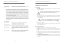
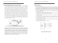
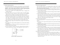
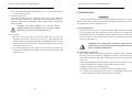
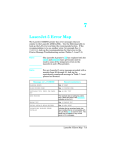
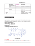
1
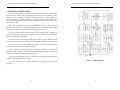
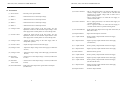
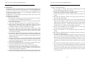
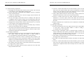
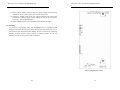
IPS 2303, 3303, 4303 Series USER MANUAL
IPS 2303, 3303, 4303 Series USER MANUAL
SAFETY TERMS AND SYMBOLS
SECTION
PAGE
1.
INTRODUCTION........……………………………………………. 1
2.
SPECIFICATIONS………………………………………..………. 2
2-1 General…………………………………………………………. 2
2-2 Operation Mode……………………………………………….. 2
2-3 Constant Voltage Operation…………………………………... 2
2-4 Constant Current Operation………………………………….. 3
2-5 Tracking Mode………………………………………………… 3
2-6 Meter………………………………………….………………... 3
2-7 CH3 Output Specification……………………………………... 3
2-8 CH4 Output Specification……………………………………... 3
2-9 Insulation………………………………………………………. 3
3.
THEORY OF OPERATION..…………………………………….. 4
4.
PANEL CONTROLS AND INDICATORS...........………………. 6
4-1 Front Panel…………………………………………………….. 8
4-2 Real Panel………………………………………….…………... 10
5.
OPERATION INSTRUCTIONS…………………….…………… 11
5-1 Precautions……..…………………………………….………... 11
5-2 Setting Current Limit…………………………………………. 11
5-3 Constant Voltage/ Constant Current Characteristics..……… 12
5-4 Operation Mode……………………………………………….. 13
6.
MAINTENANCE…......……………………………………...……. 19
6-1 Fuse Replacement……………………………………………… 19
6-2 Line Voltage Conversion………………………………………. 19
6-3 Adjustments……………………………………………………. 20
6-4 Cleaning………………………………………………………... 24
Please take a moment to review these safety terms and symbols, which may
appear in this manual or on Equipment. This may prevent injury or harm to
users, or damage to equipment.
WARNING. Warning statements identify conditions or practices
that could result in injury or loss of life.
CAUTION. Caution statements identify conditions or practices that
could result in damage to this instrument or other equipment.
DANGER! High Voltage
ATTENTION! refer to Manual
Protective Conductor Terminal
(ground) Earth Terminal
Frame or Chassis Terminal
i
ii
IPS 2303, 3303, 4303 Series USER MANUAL
IPS 2303, 3303, 4303 Series USER MANUAL
FOR UNITED KINGDOM ONLY
1. INTRODUCTION
NOTE: This lead/appliance must only be wired by competent persons
WARNING: THIS APPLIANCE MUST BE EARTHED
IMPORTANT: The wires in this lead are coloured in accordance with
the following code:
Green/ Yellow: Earth
Blue:
Neutral
Brown:
Live(Phase)
As the colours of the wires in main leads may not correspond with the colours
marking identified in your plug/appliance, proceed as follows:
The wire which is coloured Green & Yellow must be connected to the Earth terminal
marked with the letter E or by the earth symbol
or coloured Green or Green &
Yellow.
The wire which is coloured Blue must be connected to the terminal which is marked
with the letter N or coloured Blue or Black.
The wire which is coloured Brown must be connected to the terminal marked with
the letter L or P or coloured Brown or Red.
If in doubt, consult the instructions provided with the equipment, the supplier or a
competent electrician.
This cable/appliance should be protected by a suitably rated and approved HBC
mains fuse: refer to the rating information on the equipment and/or user instructions
for details. As a guide, cable of 0.75mm² should be protected by a 3A
or 5A fuse. Larger conductors would normally require 13A types, depending on the
connection method used.
Any moulded mains connector that requires removal / replacement must be
destroyed by removal of any fuse & fuse carrier and disposed of immediately, as a
plug with bared wires is hazardous if a engaged in live socket. Any re-wiring must be
carried out in accordance with the information detailed on this label.
iii
The regulated DC power supply series is designed to be used in applications such as
powering operational amplifiers, push-pull stages, logic circuits and systems where plus and
minus voltages are required to track with an insignificant error. To provide operating
convenience, the IPS-4303 has four independent power supplies (while the IPS-2303 has two
and IPS-3303 has three) housed in a single package.
The IPS-4303 consists of four identical, independent, adjustable DC power supplies
(while two for the IPS-2303 and three for IPS-3303). A front panel switch selects one of three
operation modes of independent, series and parallel. In the independent mode, the output
voltage and current of each supply are controlled separately, and each supply is isolated up to
300V from output to chassis or output to output. In the tracking mode, both outputs are
automatically connected in series or parallel, and the controls of the left supply adjust the
magnitudes of both the positive and negative output voltages. Because the outputs are
connected in a tracking configuration, any internal disturbance in the master supply (such as
drift or ripple) will cause an equal change in the outputs of both the supplies.
Each power supply (except CH3 for the IPS-3303 and CH4 for the IPS-4303) is a
completely transistorized, well-regulated, constant voltage/constant current supply that will
provide full rated output voltage at the maximum output current or can be continuously
adjusted throughout the output range. The front panel current controls can be used to establish
the output current limit (overload or short circuit) when the supply is used as a constant
voltage source (independent or tracking modes) and the voltage controls can be used to
establish the voltage limit (ceiling) when the supply is used as a constant current source
(independent mode only). The supply will automatically cross over from constant voltage to
constant current operation (current limited operation in the tracking mode). Each power
supply (CH1~CH4) has its own front panel meter that can measure output voltage or current.
One power supply may be used as a CH1 supply controlling, one CH2 supplies furnishing
various voltage or current for a system. When operate with the front panel mode switch in the
tracking position, the instrument is automatically internally connected in auto-tracking
configuration.
For audio production line use, the continuous or dynamic load can be internally selected.
When the connector (J111&J309) is connected to “ON” position the unit is suitable for audio
power Amplifier application (Normal setting to “OFF” position).
1
IPS 2303, 3303, 4303 Series USER MANUAL
2. SPECIFICATIONS
2-1. General
Main Supply (switch selectable)
Operation Environment
Storage Temperature & Humidity
Accessories
: 100V/120V/220V ± 10%(230V +10%~-6%) 50/60Hz.
: Indoor use.
Altitude up to 2000m.
Ambient temperature 0℃ to 40℃.
Relative humidity 80% (maximum).
Installation category II.
Pollution degree 2.
: -10℃ to 70℃.70% (maximum).
: Operation Manual ×1.
Table 2-1:
Model
IPS-2303
IPS-3303
IPS-4303
OUTPUT
Independent
0~30V×2
0~3A×2
0~30V×2
0~3A×2
0~30V×2
0~3A×2
Dimensions
Weight (kg)
2-2. Operation Mode
(1) Independent
(2) Series
(3)
2-3.
(1)
(2)
Series
60V
3A
60V
3A
60V
3A
Para
30V
6A
30V
6A
30V
6A
REPLACEMENT FUSE
RATED INPUT TEST LEADS
TYPE(20×5mmHBC)
100V/120V 220V/230V WATTS VA
(QTY)
T6A
T3.15A
350
450
2
250V
250V
T6.3A
T3.15A
420
550
3
250V
250V
T6.3A
T3.15A
420
550
4
250V
250V
: 255(W) ×145(H) ×265(D) m/m
: 7.0 kg.
: Two independent outputs and
CH3: 2.2~5.2V output for IPS-4303,
Fixed 5V for IPS-3303,
CH4: 8~15V output for IPS-4303.
Output from 0 to rated voltage and 0 to rated current.
: Output from 0 to rated voltage at rated current each.
: Output from 0 to twice rated voltage at rated current.
: Output from 0 to twice rated current at rated volts.
Parallel
Constant Voltage Operation
Output voltage range
: 0 to rated voltage, continuously adjustable.
Regulation
: Line regulation≦0.01% + 3mV.
: Load regulation≦0.01%+3mV(rated current≦3A).
: Load regulation≦0.02%+5mV (rated current>3A).
(3) Recovery time
: ≦100μs (50% load change, minimum load 0.5A ).
(4) Ripple & Noise
: ≦1mVrms (5Hz-1MHz ).
(5) Temperature coefficient
: ≦300ppm/℃.
2
IPS 2303, 3303, 4303 Series USER MANUAL
2-4. Constant Current Operation
(1) Output current range
: 0 to rated current continuously adjustable.
(2) Regulation
: Line regulation≦0.2% + 3mA.
: Load regulation≦0.2% +3mA.
(3) Ripple current
: ≦3mArms.
2-5. Tracking Operation
(1) Parallel Operation
Regulation
: Line regulation≦0.01% + 3mV.
: Load regulation≦0.01%+3mV (rating current≦3A).
≦0.02%+5mV (rating current >3A).
(2) Series Operation
Regulation
: Line regulation≦0.01%+5mV.
: Load regulation≦300mV.
A. Positive and Negative supply (Fig 5-4) CH2 tracking error ≦0.5%+10mV of the
CH1 (No load, with load add load regulation≦300mV)
B. Single supply (Fig. 5-3)
2-6. Meter
A. Display A
: 3 digits panel meter×2 (0.5” Red LED display).
Display V
: 3 digits panel meter × 2 (0.5” Green LED display).
B. Accuracy
: OUTPUT ON±(0.5% of rdg + 2 digits)
: OUTPUT OFF±(0.5% of rdg + 8 digits)(not for IPS-2303)
C. Voltmeter
: 99.9V full scale.
D. Ammeter
: 9.99A full scale.
2-7. CH3 Output Specifications
(1) Regulation
: Line regulation≦5mV, load regulation≦15mV.
(2) Ripple & Noise
: ≦2mVrms.
(3) Output Voltage range
: IPS-4303: 2.2~5.2V±8% continuous adjustment.
IPS-3303 fixed 5V±8% continuous adjustment.
(4) Output current
: 3A for IPS-3303, 1A for IPS-4303.
2-8. CH4 Output Specifications
(1) Regulation
: Line regulation≦5mV, load regulation≦10mV.
(2) Ripple & Noise
: ≦2mVrms.
(3) Output Voltage range
: IPS-4303: 8~15V±8% continuous adjustment.
(4) Output current
: 1A
2-9. Insulation
Between chassis and output terminal : 20MΩ or above (DC 500V).
Between chassis and AC cord
: 30MΩ or above (DC 500V).
3
IPS 2303, 3303, 4303 Series USER MANUAL
IPS 2303, 3303, 4303 Series USER MANUAL
3. THEORY OF OPERATION
The power supply consists of an AC input circuit and transformer; a bias supply
consisting of an rectifier, filter, pre-regulator and reference voltage source; a main
regulator circuit consisting of the main rectifier and filter, a series regulator, a
current comparator, a voltage comparator, a reference voltage amplifier and a relay
control circuit. The circuit element consists of integrated circuit U101, U102, U103,
U104, U105, U108.
The circuit arrangement is shown as block diagram in Fig. 3-1. The circuitry is
discussed with reference to the block diagram function description. Single phase
input power is applied to the transformer through the input circuit.
Auxiliary rectifier D1021~1024 provides a bias voltage which is filtered by
capacitor C103 and C104 for the pre-regulator. U101, U108 provides a regulator
voltage for the active components.
The main rectifier is a full wave bridge that provides the power which is filtered
by capacitor C1021, then regulated via a series regulator and delivered to the output.
U105 acts as a current limiter. When the output current is over predetermined
value, U105 is activated and reduces the output.
U102 provides a reference voltage for U103 and U105. U103 is an inverting
amplifier. U104 compares a reference voltage and feedback voltage, drives Q103
and Q104, which then calibrate the output voltage.
Q113 is activated when the unit is overloaded. It controls the current magnitude
of Q103, which limits the output current.
The relay control circuit provides limited power dissipation in the series
regulator.
4
Figure 3-1 Block Diagram
5
IPS 2303, 3303, 4303 Series USER MANUAL
IPS 2303, 3303, 4303 Series USER MANUAL
4. PANEL CONTROLS AND INDICATORS
Fig. 4-1 Front Panel
6
Fig. 4-2 Real Panel
7
IPS 2303, 3303, 4303 Series USER MANUAL
4-1. Front Panel
(1) Power switch
: Turns the power input ON/OFF
(2) Meter V
: Indicates the CH1 or CH3 output voltage.
(3) Meter A
: Indicates the CH1 or CH3 output current.
(4) Meter V
: Indicates the CH2 or CH4 output voltage.
(5) Meter A
: Indicates the CH2 or CH4 output current.
(6) Voltage Control
: Adjusts the output voltage of the CH1 supply. Also the
adjustment control for the maximum output voltage of the
CH2 supply when in either parallel or series tracking mode.
(7) Current Control
: Adjusts the output current of the CH1 supply, Also the
adjustment control for the maximum output current of the
CH2 supply when in either parallel or series tracking mode.
IPS 2303, 3303, 4303 Series USER MANUAL
(15) CV&CC Indicator
: The CV light (green LED) is on when the CH1 supply is in
constant voltage mode, or when both the CH1 and CH2
supplies are in constant voltage mode in either series or
parallel tracking mode.
: The CC light (red LED) is on when the CH1 supply is in
constant current mode.
(16) CV&CC Indicator
: The CV light (green LED) is on when the CH2 supply is in
constant voltage mode.
: The CC light (red LED) is on when the CH2 supply is in
constant current mode or in parallel tracking mode.
(17) Overload Indicator : Lights when CH4 output load is larger than rated value (not
IPS-2303 & 3303).
(18) Output Indicator
: Lights when the output is turned on.
(19) + output terminal
: Positive polarity output terminal for the CH3 supply
(not IPS-2303).
(8) Voltage Control
: Adjusts the output voltage of the CH2 supply when in
independent operation.
(20) - output terminal
: Negative polarity output terminal for the CH3 supply
(not IPS-2303).
(9) Current Control
: Adjusts the output current of the CH2 supply.
(21) + output terminal
: Positive polarity output terminal for the CH1 supply.
(10) Voltage Control
: Adjusts the output voltage of the CH3 supply (not IPS-2303
& 3303).
(22) - output terminal
: Negative polarity output terminal for the CH1 supply.
(11) Voltage Control
: Adjusts the output voltage of the CH4 supply (not IPS-2303
& 3303).
(23) GND terminal
: Earth and chassis ground.
(24) + output terminal
: Positive polarity output terminal for the CH2 supply.
(25) - output terminal
: Negative polarity output terminal for the CH2 supply.
(26) + output terminal
: Positive polarity output terminal for the CH4 supply
(not IPS-2303 & 3303).
(27) - output terminal
: Negative polarity output terminal for the CH4 supply
(not IPS-2303 & 3303).
(28) Output switches
: Turns the output ON/OFF.
(12) CH1/CH3
select switch
: Selects CH1 or CH3 output voltage or current (not IPS-2303
& 3303).
(13) CH2/CH4
select switch
: Selects CH2 or CH4 output voltage or current (not IPS-2303
& 3303).
(14) Overload Indicator : Lights when CH3 output load is greater than rated output
(not IPS-2303).
8
9
IPS 2303, 3303, 4303 Series USER MANUAL
(29) TRACKING
& Mode Switches
(30)
Two push-button switches that select Independent mode, series
tracking mode, or parallel tracking mode as follows:
a. When both switches are disengaged (out), the unit is in the Independent mode and
the CH1 and CH2 power supplies are completely independent from each other.
b. When the left switch is engaged (in) and the right switch is disengaged (out), the
unit is in the series Tracking mode. Maximum voltage of both supplies is set using
the CH1 VOLTAGE controls (voltage at output terminals of the CH2 supply
tracks the voltage at the output terminals of the CH1 SUPPLY). Also, in this mode
of operation, the positive terminal (Red) of the CH2 supply is connected to the
negative terminal (Black) of the CH1 supply to allow the two supplies to be used
as a 0 to double rated voltage supply.
c. When both switches are engaged (in), the unit is in the Parallel Tracking mode.
The control of both CH1 and CH2 supplies are internally linked and the maximum
current and voltage for both channels are set using the CH1 controls. The CH1 and
CH2 output can be used as two individual (but tracking) power supplies, or just the
CH1 output can be used as a 0 to rated voltage supply with a 0 to double rated
current capability.
(32) Power socket
: Contains the 20 x 5 mm HBC fuse of the appropriate
rating, depending on the line voltage selected.
: IEC inlet socket to connect to the power cable.
(33) AC selector switch : Used to select operation from 100, 120, 220 or 230VAC,
&
50/60Hz line voltage in conjunction with (34) HI-LO switch.
(34) HI-LO switch
: HI position selects high voltage range (120, 230V AC inputs),
LO position selects low voltage range (100, 220V AC
inputs).
(35) Cooling Fan
5. OPERATION INSTRUCTION
5-1. Precaution
(1) AC input
AC input should be within the range of line voltage ± 10% (230V
+10%~-6%) 50/60Hz.
WANING. To avoid electrical shock, the power cord protective
grounding conductor must be connected to ground.
(2) Installation
Avoid using the supply in a place where ambient temperature exceeds 40℃.
The fan grille at the rear of the supply must have sufficient space to allow air
to flow unimpeded.
CAUTION. To avoid damaging the power supply, do not use
it in a place where ambient temperature exceeds 40℃.
4-2. Real Panel
(31) Fuse holder
IPS 2303, 3303, 4303 Series USER MANUAL
: Provides forced ventilation for the internal components, to
prevent output stage from overheating and improves the
stability of the output due to temperature changes.
10
(3) Output voltage overshoot
Voltage at the output terminals never exceeds the preset value when the
power is turned on or off.
5-2. Setting Current Limit
(1) Determine the maximum safe current for the device to be powered.
(2) Temporarily short the (+) and (-) terminals of the power supply together with a test
lead.
(3) Rotate the VOLTAGE control away from zero sufficiently for the CC indicator to
light.
(4) et the meter selection switch to “A” position to select the current metering mode.
(5) Adjust the CURRENT control for the desired current limit. Read the current value
on the Ammeter.
(6) The current limit (overload protection) has now been preset. Do not change the
CURRENT control setting after this step.
(7) Remove the short between the (+) and (-) terminals and connect for constant voltage
operation.
11
IPS 2303, 3303, 4303 Series USER MANUAL
5-3. Constant Voltage/Constant Current Characteristics
The operating principle of these Power Supplies is a of constant
voltage/constant current type, with automatic crossover from one mode to the
other. This permits continuous transition from constant current to constant
voltage modes in response to load changes. The intersection point of the
constant voltage and constant current modes is known as the crossover point.
Fig. 5-1 shows the relationship between this crossover point and the load.
For example, if the load is such that the power supply is operating in the
constant voltage mode, a regulated output voltage is provided. The output
voltage remains constant as the load increases, up until the point where the
preset current limit is reached. At that point, the output current becomes
constant and the output voltage drops in proportion to further increases in load.
The crossover point is indicated by the front panel LED indicators. The
crossover point is reached when the CV (Green LED) indicator goes off and the
CC (Red LED) indicator comes on.
Fig. 5-1 Constant Voltage/Constant Current Characteristic
Similarly, crossover from the constant current to the constant voltage mode
automatically occurs from a decrease in load. A good example of this would be
seen when charging a 12 volt battery. Initially, the open circuit voltage of the
power supply may be preset for 13.8 volts. A low battery will place a heavy
load on the supply and it will operate in the constant current mode, which may
be adjusted for a 1 amp charging rate. As the battery becomes charged, and its
voltage approaches 13.8 volts, its load decreases to the point where it no longer
demands the full 1 amp charging rate. This is the crossover point where the
power supply goes into the constant voltage mode.
12
IPS 2303, 3303, 4303 Series USER MANUAL
5-4. Operation Mode
(1) Independent Operation
The “CH1” and “CH2” supplies each provides a 0 to rated voltage output at up
to rated current. This procedure covers the use of the CH1 and CH2 supplies,
only when they are used independently from each other. When used in the
independent operating mode, the operation controls of the two power supplies
are completely independent and either supply can be used individually or both
can be used simultaneously.
A. Disengage both Tracking mode switches (both switches out) so that the
power supply is in the independent operating mode.
B. Adjust “Voltage” control and “Current” control to the desired output
voltage and current.
C. Turn off the power supply and the equipment whilst making connections..
D. Connect the positive connection of the device being powered to the red (+)
terminal of the power supply.
E. Connect the negative connection of the device being powered to the black (-)
terminal of the power supply.
F. Fig.5-2 illustrates the connection procedure.
Power
Supply
Fig. 5-2 Independent Operation
13
IPS 2303, 3303, 4303 Series USER MANUAL
(2) Series Tracking Operation
When the series tracking mode of operation is selected, the position (Red)
terminal of the CH2 supply output is internally connected to the negative
(black) terminal of the CH1 supply.
In series tracking mode, the maximum output voltage of both CH1 and CH2
supplies can be simultaneously varied with one control. The maximum CH2
supply voltage is automatically set to the same as the CH1 supply by using the
CH1 VOLTAGE controls.
A. Set the power supplies to the Tracking series mode by engaging the left
Tracking switch and release the right Tracking switch.
IPS 2303, 3303, 4303 Series USER MANUAL
rotated fully clockwise and the CH2 CURRENT control can be used to adjust
the maximum current value. Because current through the two supplies must be
equal when they are being used in series, the lowest CURRENT control
setting will set the maximum output current.
C. Adjust the output voltage to the desired level by using the CH1 VOLTAGE
controls.
D. Turn off the power supply and the equipment whilst making connections.
E. If “single supply” operation is required, this allows the power supply to be
used at twice the voltage and rated current simply by using the negative
(black) terminal of the CH2 supply and the positive (red) terminal of the
CH1 supply, the configuration as shown in Fig. 5-3.
WARNING. Voltages greater than 60V DC present a lethal shock
hazard to the user. Take care when connecting power supplies in
series to achieve voltages higher than 60V DC total, or 60V DC
between any connection and earth ground.
Note:
Power
Simultaneous metering of both current and voltage can be obtained in this
mode of operation by setting one of the displays for current metering and one
for voltage metering. In this case, the output voltage (across the two supplies)
is actually double the displayed value. For example, if the CH1 display is set
for voltage metering and the CH2 display for current metering, the output
voltage across the CH1 positive (red) terminal and the CH2 negative (black)
terminal would be double the reading on the CH1 LED Display (since both
supplies are providing the same voltage). The actual output current would be
the value read from the CH2 LED Display (since the two supplies are
connected in series, current flowing through each supply must be equal).
B. Set the CH2 CURRENT control to the full clockwise position. The
maximum current is set by using the CH1 CURRENT control. Follow the
instructions for “Setting Current Limit” (select “CH1” or “CH2” supply
independently by using the CH1 CURRENT control).
Note:
Because the supplies are being used in series, either CURRENT control can be
used to set maximum current. If desired, the CH1 CURRENT control can be
Supply
14
Fig. 5-3 Single Supply
F. If the chassis or common of the equipment being powered is separated from
both the positive and negative power input connections, the output of the
CH2 (negative) supply tracks the output of the CH1 (positive) supply,. The
configuration is shown in Fig. 5-4.
Power
Supply
Fig. 5-4 Positive and Negative Supply
15
IPS 2303, 3303, 4303 Series USER MANUAL
IPS 2303, 3303, 4303 Series USER MANUAL
(3) Parallel Tracking Operation
In the parallel tracking mode of operation, both supplies are connected together
(in parallel). This allows for a rated voltage supply with double the rated current
capability. Only the CH1 output terminals are used for parallel tracking
operation. In the parallel tracking mode, the CH2 supply output voltage and
current track the CH1 supply output voltage and current.
A.Set the power supplies to the Tracking Parallel mode by engaging both
Tracking switches.
B.The output voltage will now be read from the CH1 VOLTAGE display.
Output current is exactly double the value read from the CH1 CURRENT
display (because each supply is providing the same amount of current).
C.Because both voltage and current of the CH2 supply track the CH1 supply, the
maximum current and voltage are set by using the CH1 controls. Using the
CH1 supply output terminals, follow the instructions for “Setting Current
Limit” (Section 5-2). Remember that the actual current output at the CH1
supply output terminals is double the reading on the CH2 indicator meter.
D.Adjust the output voltage to the desired level by using the CH1 VOLTAGE
controls.
E. Turn off the power supply and the equipment to be powered whilst making
connections.
F. Connect the positive connection of the device being powered to the red (+)
terminal of the CH1 power supply.
G. Connect the negative connection of the device being powered to the black (-)
terminal of the CH1 power supply. The configuration is shown as Fig. 5-5:
(4) CH3 Power Supply Operation
The CH3 supply provides a 2.2~5.2V(IPS-4303) DC output with a 3 amps
(IPS-3303) and 1 amp (IPS-4303) current capacity. The supply is ideal for us
with TTL circuits (IPS-3303 5V Fixed).
A. Turn off the power supply and the equipment whilst making connections.
B. Connect the positive connection of the device being powered to the red (+)
terminal of the CH3 supply.
C. Connect the negative connection of the device being powered to the black (-)
terminal of the CH3 supply.
D. If the red OVERLOAD indicator lights, an excessive load has been placed
on the supply. This will cause the output voltage and current to drop and
inhibit the proper operation of the CH3 supply. To correct this situation, the
load on the supply must be decreased so that no more than 3 amps
(IPS-3303), or 1amp (IPS-4303) of current is drawn.
(5) CH4 Power Supply Operation
The CH4 supply provides a 8~15V(IPS-4303) DC output with a 1 amp current
capacity.
A.Turn off the power supply and the equipment to be powered whilst making
connections.
B. Connect the positive connection of the device being powered to the red (+)
terminal of the CH4 supply.
C. Connect the negative connection of the device being powered to the black (-)
terminal of the CH4 supply.
D. If the red OVERLOAD indicator lights, an excessive load has been placed
on the supply. This will cause the voltage and current to drop and inhibit
proper operation of the CH4 supply. Under this situation, the load on the
supply must be decreased so that no more than 1 amps of current is drawn.
(6) Dynamic Load Operation & Application
A. When select to the dynamic load position, the peak current available is 1.7
times the rated current. This feature is only intended for audio circuits of
amplifiers and audio production lines. Change the position of wafers J111
of CH1 and J309 of CH2 from “OFF” to “ON”. Please refer to Fig.6-1:
Adjustment Location.
Power
Supply
Fig. 5-5 Parallel Tracking Operation
16
17
IPS 2303, 3303, 4303 Series USER MANUAL
B. For other application and testing (Safety or CE. etc.), the selectors must be
set at the “OFF” position
(7) Output ON/OFF Action
The output ON/OFF action is controlled with a single control. When the
output switch is pushed on, the single output turns on and output LED is lit.
While the output switch is pushed off, or the tracking switch is on, the output
will be disabled.
IPS 2303, 3303, 4303 Series USER MANUAL
6. MAINTENANCE
WARNING
The following instructions are for use by qualified personnel only. To avoid
electrical shock, do no perform any servicing other than the operation instruction of
this manual unless you are qualified to do so.
CAUTION: The output terminals are for use only with the
equipment which has no accessible live parts. The output terminals
should not be connected to any hazardous live parts.
(8) Fan Control
1) The fan of the power supply will not work upon power on until the
temperature of the heat sink rises up to 32℃±5℃ after adding load to
output terminal. The more the temperature of the heat sink rises, the more
the rolling speed of the fan gets fast. The fastest rolling speed is when the
temperature reaches to 70℃.
2) To avoid damaging the power supply, if the fan fails to work when the
temperature reached to the appropriate value, turn off the instrument and
check the cause.
18
6-1. Fuse Replacement
If the fuse blows, the CV or CC indicators will not light and the power supply
will not operate. The fuse should not normally fail unless a problem has
developed in the unit. Try to determine and correct the cause, then replace only
with a fuse of the correct rating and type. The fuse is located on the rear panel
(see Fig.4-2 & Table 2-1).
WARNING: For continued fire protection, replace the fuse
with 250V fuse of the specified type and rating only. Disconnect
power cord before replacing fuse.
6-2. Line Voltage Conversion
The primary winding of the power transformer is tapped to permit operation
from 100, 120, 220, or 230VAC, 50/60Hz line voltage. Conversion from one
line voltage to another is achieved by changing the AC selector switch as shown
in Fig. 4-2.
The rear panel identifies the line voltage to which the unit was factory set. To
convert to a different line voltage, perform the following procedure:
(1) Make sure the power cord is unplugged.
(2) Change the AC selector switch to the desired line voltage position.
(3) A change in line voltage may also require a corresponding change of fuse
value. Install the correct fuse value as listed on rear panel.
19
IPS 2303, 3303, 4303 Series USER MANUAL
6-3. Adjustments
This unit was accurately adjusted at the factory before shipment. Readjustment is
recommended only if repairs have been made in a circuit affecting adjustment
accuracy, or if you have a reason to believe the unit is out of adjustment. The
recommended calibration device is a 4+1/2 digit digital multimeter with an
accuracy of ±0.1% DCV or better
If readjustment is required, use the following procedure. The location of the
adjustments is shown in Fig. 6-1.
(1) Independent Adjustment
A. Disengage both Tracking mode switches (both switches out) so that the
power supply is in the independent operating mode.
B. Connect the multimeter to measure the DC voltage at the output terminals
of the CH1 (CH2) supply.
C. Set the CH1 (CH2) VOLTAGE control to maximum (fully clockwise).
D. Adjust trimmer potentiometer (VR101 CH1,VR301 CH2) on the circuit
board (located on the right side of the supply) for a reading as close to
rated output voltage ×1.05 (on the multimeter) as possible.
E. Set output on. Adjust the trimmer potentiometer (VR801 CH2, VR201
CH1) from the CH1 (CH2) on the voltage indicator circuit board (located
on the meter or A/D converter board) for a reading of rated output voltage
×1.05 on the CH1 (CH2).
F. Set output off. Adjust trimmer potentiometer (VR802 CH2, VR202 CH1)
from the CH1 (CH2)on the voltage indicator circuit board (located on the
meter or A/D converter board) for a reading of rated voltage on the CH1
(CH2)(not IPS-2303)
G. Connect the multimeter across the CH1 (CH2) SUPPLY output terminals
to read the output current (so that the meter causes a short circuit across
the terminals) and adjust the CH1 (CH2) CURRENT control so that rated
amps is read on the multimeter.
H. Set output on and adjust the trimmer potentiometer (VR901 CH2, VR701
CH1) so that the CH1(CH2) meter also reads rated amps.
I. Rotate the CH1(CH2) current control fully clockwise (maximum).
J. Adjust VR103 on the CH1 (VR303 CH2)supply circuit board (located on
the right side of the supply) to obtain an output current of rated amps ×
1.05 (read on the meter or LED display).
K. Set output off and adjust the trimmer potentiometer (VR903 CH2, VR703
CH1) so that the CH1(CH2) meter also reads rated amps (not IPS-2303).
20
IPS 2303, 3303, 4303 Series USER MANUAL
(2) Series Tracking Adjustment
A. Set the supply to Tracking series mode by engaging the left Tracking
switch and releasing the right tracking switch.
B. Set the CH2 CURRENT control to midrange and set the CH1 supply
voltage controls to minimum (fully counterclockwise).
C. Connect the multimeter to the CH1 SUPPLY outputs and measure the
voltage.
D.Disconnect the multimeter from the CH1 supply outputs and connect it
across the CH2 supply outputs.
E. Adjust trimmer potentiometer VR306 on the circuit board (located on the
right side of the supply) to obtain the exact same reading for the CH2
supply output as was preset at the CH1 supply output (e.g., if the minimum
CH1 supply output voltage is –10.00mV adjust VR306 to obtain an output
voltage as close to -10.00mV at the CH2 supply as possible).
F. Set the CH2 CURRENT control to midrange and set the CH1 supply
voltage controls to maximum (fully clockwise).
G. Connect the multimeter to the CH1supply outputs and measure the
voltage.
H. Disconnect the multimeter from the CH1supply outputs and connect it
across the CH2 supply outputs.
I. Set output on by adjusting VR501 (located at the left of the lower front
panel circuit board, VOLTAGE/CURRENT CONTROL potentiometer
board) until the voltage read from the multimeter is the same as it was
across the CH1 output terminals. Return the multimeter to the CH1 output
terminals and verify that the output voltage is identical. If not, repeat this
step.
J. Set output off by adjusting VR804 (located at the left of the lower front
panel circuit board, VOLTAGE/CURRENT CONTROL potentiometer
board) until the voltage read from the multimeter is the same as it was
across the CH1 output terminals. Return the multimeter to the CH1 output
terminals and verify that the output voltage is identical. If not, repeat this
step (not IPS-2303).
21
IPS 2303, 3303, 4303 Series USER MANUAL
(3) Parallel Tracking Adjustment
A. Disengage both Tracking mode switches (both switches out) so that the
power supply is in the independent operating mode.
B. Set the CH1 supply VOLTAGE and CURRENT controls to minimum
(fully counterclockwise).
C. Connect the multimeter across the CH1 supply output terminals and
measure the output current.
D. Set the CH1 supply VOLTAGE control to midrange and adjust the
CURRENT control to obtain an output current of rating amps (read on the
multimeter). Do not change the CURRENT control setting after this step.
E. Engaged both Tracking mode switches (both switches in), so that the
power supply is in the parallel operating mode.
F. Set the CH2 supply CURRENT control to maximum (fully clockwise)
and set the VOLTAGE control to midrange.
G. Set output on and adjust the trimmer potentiometer VR502 on the circuit
board (located on the right side of the supply) to obtain an output current
of double the rated amps on the multimeter.
(4) CH3 Supply Adjustment
A. Connect the multimeter across the output terminals of the CH3 supply to
read output voltage and adjust the VR403 to obtain reading of
2.2~5.2V(IPS-4303) and fixed 5V(IPS-3303) on the multimeter.
B. Set the supply VOLTAGE control to maximum (fully clockwise). Set
output off and adjust trimmer potentiometer VR203 on the CH3 voltage
indicator circuit board (located on the meter or A/D converter board) for a
reading of rated voltage on the CH3 (invalid for IPS-3303).
C. Turn VR401 on the main master circuit board (located on the right side of
the supply) fully counterclockwise.
D. Set output on and adjust VR702 so that the CH3 meter also reads rated
amps (invalid for IPS-3303).
22
IPS 2303, 3303, 4303 Series USER MANUAL
E. Connect a variable load (load must be rated to handle a power of at least
30W) across the output terminals and connect the multimeter to read the
output current, then adjust the load on the multimeter to show an output
current at 3.25A for IPS-3303 and 1.20A for IPS-4303.
F. Slowly adjust VR402 clockwise until the output voltage (read from the
multimeter) drops 5mV to 6mV (start of current limit point).
G. Connect a variable load across the output terminals and connect the
multimeter to read the output current, then adjust the load on the
multimeter to show an output current at 3.15A for IPS-3303 and 1.10A for
IPS-4303.
H. Adjust VR402 until the 3A (IPS-3303) and 1A (IPS-4303) OVERLOAD
indicator light.
(5) CH4 Supply Adjustment
A. Connect the multimeter across the output terminals of the CH4 SUPPLY
to read output voltage and adjust VR603 to obtain a reading of
8~15V(IPS-4303) on the multimeter.
B. Set the supply VOLTAGE control to maximum (fully clockwise), set
output off and adjust the trimmer potentiometer VR803 from the CH4
voltage indicator circuit board (located on the meter or A/D converter
board) for a reading of rated output voltage on CH4.
C. Turn VR601 on the main master circuit board (located on the right side of
the supply) fully counterclockwise.
D. Set output on by adjusting VR902 so that the CH4 meter also reads rating
amps.
E. Connect a variable load (load must be rated to handle a power of at least
30W) across the output terminals and connect the multimeter to read the
output current. Adjust the load to show an output current of 1.20A on the
multimeter.
23
IPS 2303, 3303, 4303 Series USER MANUAL
IPS 2303, 3303, 4303 Series USER MANUAL
F. Slowly adjust VR602 clockwise until the output voltage (read from the
multimeter) drops to 5mV~6mV (start current limit point).
G. Connect a variable load across the output terminals and connect the
multimeter to read the output current. Adjust the load to show an output
current at 1.10A on the multimeter.
H. Adjust VR602 until the 1.10A OVERLOAD indicator just lights.
6-4. Cleaning
To clean the power supply, use a soft cloth dampened in a solution of mild
detergent and water. Do not spray cleaner directly onto the instrument, since it
may leak into the cabinet and cause damage. Do not use chemicals containing
benzine, benzene, toluene, xylene, acetone, or similar solvents. Do not use
abrasive cleaners on any portion of the instrument.
Fig. 6-1. Adjustment Location
24
25