1
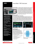
72-7570
DUAL 60V 20A POWER FLEX POWER SUPPLY
INSTRUCTION MANUAL
Tenma 72-7570 Instruction manual
Table of Contents
Specification
1
Safety
3
EMC
4
Installation
5
Connections
5
Operation
6
Maintenance
8
Specification
General specifications apply for the temperature range 5°C to 40°C. Accuracy specifications
apply for the temperature range 18°C to 28°C after 1 hour warm-up with no load and calibration at
23°C. Typical specifications are determined by design and are not guaranteed.
OUTPUT SPECIFICATIONS
Voltage Range:
0V to 60V
Current Range:
0A to 20A
Power Range:
Up to 420W
Output Voltage Setting:
By coarse and fine controls.
Output Current Setting:
By single logarithmic control.
Operating Mode:
Constant voltage or constant current with automatic cross-over
provided that the power demanded stays within the power envelope,
see graph. Outside of this envelope the output becomes unregulated.
72 - 7570
POWER ENVELOPE
www.tenma.com
1
Tenma 72-7570 Instruction manual
Output Switch:
Electronic. Preset voltage and current displayed when off.
Output Terminals:
Universal 4mm safety binding posts on 19mm (0·75”) pitch. 30A max.
Sensing:
Switchable between local and remote. Spring-loaded push terminals
for remote connection.
Output Protection:
Forward protection by Over-Voltage Protection (OVP) trip; maximum
voltage that should be applied to the terminals is 70V.
Reverse protection by diode clamp for reverse currents up to 3A.
Over-temperature Protection:
The output will be tripped off if a fault causes the internal temperature
to rise excessively.
OVP Range:
10% to 110% of maximum output voltage set by front panel screwdriver
adjustment.
Line Regulation:
Change in output for a 10% line change <0.01% of maximum output.
Load Regulation:
Change in output for any load change within PowerFlex envelope,
remote sense connected, <0.05% of maximum output.
Ripple & Noise
(20MHz bandwidth):
4mVrms max; typically <2mVrms, <10mV pk-pk, at maximum load, CV
mode.
Transient Load Response:
<250us to within 50mV of set level for a 5% to 95% load change.
Temperature Coefficient:
Typically <100ppm/°C
Status Indication:
Output on lamp.
Constant voltage mode lamp.
Constant current mode lamp.
Unregulated (power limit) lamp
Trip message on display.
METER SPECIFICATIONS
Meter Types:
Dual 4 digit meters with 12.5mm (0.5") LEDs. Reading rate 4 Hz.
Meter Resolutions:
10mV, 10mA
Meter Accuracies:
Voltage 0.1% of reading ± 2 digits,
Current 0.3% of reading ± 2 digits
GENERAL
AC Input:
110V – 240V AC ± 10%, 50/60Hz. Installation Category II.
Power Consumption:
1250VA max.
Operating Range:
+5ºC to +40ºC, 20% to 80% RH.
Storage Range:
−40ºC to + 70ºC.
Environmental:
Indoor use at altitudes up to 2000m, Pollution Degree 2.
Safety:
Complies with EN61010-1.
EMC:
Complies with EN61326.
Size:
210 x 130 x 375mm (WxHxD) half rack width x 3U height (optional rack
mounting kit available).
Weight:
6kg
2
www.tenma.com
Tenma 72-7570 Instruction manual
Safety
This power supply is a Safety Class I instrument according to IEC classification and has been
designed to meet the requirements of EN61010-1 (Safety Requirements for Electrical Equipment
for Measurement, Control and Laboratory Use). It is an Installation Category II instrument
intended for operation from a normal single phase supply.
This instrument has been tested in accordance with EN61010-1 and has been supplied in a safe
condition. This instruction manual contains some information and warnings which have to be
followed by the user to ensure safe operation and to retain the instrument in a safe condition.
This instrument has been designed for indoor use in a Pollution Degree 2 environment in the
temperature range 5°C to 40°C, 20% - 80% RH (non-condensing). It may occasionally be
subjected to temperatures between +5°C and –10°C without degradation of its safety. Do not
operate while condensation is present.
Use of this instrument in a manner not specified by these instructions may impair the safety
protection provided. Do not operate the instrument outside its rated supply voltages or
environmental range.
WARNING! THIS INSTRUMENT MUST BE EARTHED
Any interruption of the mains earth conductor inside or outside the instrument will make the
instrument dangerous. Intentional interruption is prohibited. The protective action must not be
negated by the use of an extension cord without a protective conductor.
When the instrument is connected to its supply, terminals may be live and opening the covers or
removal of parts (except those to which access can be gained by hand) is likely to expose live
parts. The apparatus shall be disconnected from all voltage sources before it is opened for any
adjustment, replacement, maintenance or repair. Capacitors inside the power supply may still be
charged even if the power supply has been disconnected from all voltage sources but will be
safely discharged about 10 minutes after switching off power.
Any adjustment, maintenance and repair of the opened instrument under voltage shall be avoided
as far as possible and, if inevitable, shall be carried out only by a skilled person who is aware of
the hazard involved.
If the instrument is clearly defective, has been subject to mechanical damage, excessive moisture
or chemical corrosion the safety protection may be impaired and the apparatus should be
withdrawn from use and returned for checking and repair.
Make sure that only fuses with the required rated current and of the specified type are used for
replacement. The use of makeshift fuses and the short-circuiting of fuse holders is prohibited.
Do not wet the instrument when cleaning it.
The following symbols are used on the instrument and in this manual:Earth (ground) terminal.
Instrument in STAND-BY
l
mains supply ON.
alternating current (ac)
www.tenma.com
3
Tenma 72-7570 Instruction manual
EMC
This instrument has been designed to meet the requirements of the EMC Directive 2004/108/EC.
Compliance was demonstrated by meeting the test limits of the following standards:
Emissions
EN61326-1 (2006) EMC product standard for Electrical Equipment for Measurement, Control and
Laboratory Use. Test limits used were:
a)
b)
c)
Radiated: Class B
Conducted: Class B
Harmonics: EN61000-3-2 (2000) Class A; the instrument is Class A by product category
Immunity
EN61326-1 (2006) EMC product standard for Electrical Equipment for Measurement, Control and
Laboratory Use.
Test methods, limits and performance achieved are shown below (requirement shown in
brackets):
a)
EN61000-4-2 (1995) Electrostatic Discharge : 4kV air, 4kV contact, Performance A (B).
b)
EN61000-4-3 (2006) Electromagnetic Field:
3V/m, 80% AM at 1kHz, 80MHz – 1GHz: Performance A (A) and
1.4GHz to 2GHz: Performance A (A); 1V/m, 2.0GHz to 2.7GHz: Performance A (A).
c)
EN61000-4-11 (2004) Voltage Interrupt:
½-cycle, 0%: Peformance A (B); 1 cycle, 0%: Performance B (B);
25 cycles, 70%: Performance A (C); 250 cycles, 0%: Performance B (C).
d)
EN61000-4-4 (2004) Fast Transient, 1kV peak (AC line), 0·5kV peak (DC Outputs),
Performance B (B).
e)
EN61000-4-5 (2006) Surge, 0·5kV (line to line), 1kV (line to ground), Performance B (B).
f)
EN61000-4-6 (2007) Conducted RF, 3V, 80% AM at 1kHz (AC line only; DC Output
connections <3m, therefore not tested), Performance A (A).
According to EN61326-1 the definitions of performance criteria are:
Performance criterion A: ‘During test normal performance within the specification limits.’
Performance criterion B: ‘During test, temporary degradation, or loss of function or
performance which is self-recovering’.
Performance criterion C: ‘During test, temporary degradation, or loss of function or
performance which requires operator intervention or system reset occurs.’
Where Performance B is stated it is because DC Output regulation, or V & I measurement
accuracy, may deviate beyond Specification limits under the test conditions. However, the
possible deviations are still small and unlikely to be a problem in practice.
Note that if operation in a high RF field is unavoidable it is good practice to connect the PSU to
the target system using screened leads which have been passed (together) through an absorbing
ferrite sleeve fitted close to the PSU terminals.
Cautions
To ensure continued compliance with the EMC directive observe the following precautions:
a) after opening the case for any reason ensure that all signal and ground connections are
remade correctly and that case screws are correctly refitted and tightened.
b) In the event of part replacement becoming necessary, only use components of an identical
type, see the Service Manual.
4
www.tenma.com
Tenma 72-7570 Instruction manual
Installation
Mains Operating Voltage
This instrument has a universal input range and will operate from a nominal 115V or 230V mains
supply without adjustment. Check that the local supply meets the AC Input requirement given in
the Specification.
Mains Lead
Connect the instrument to the AC supply using the mains lead provided. Should a mains plug be
required for a different mains outlet socket, a suitably rated and approved mains lead set should
be used which is fitted with the required wall plug and an IEC60320 C13 connector for the
instrument end. To determine the minimum current rating of the lead-set for the intended AC
supply, refer to the power rating information on the equipment or in the Specification.
WARNING! THIS INSTRUMENT MUST BE EARTHED.
Any interruption of the mains earth conductor inside or outside the instrument will make the
instrument dangerous. Intentional interruption is prohibited.
Ventilation
The power supply is cooled by an intelligent multi-speed fan which vents at the rear. Take care
not to restrict the air inlets at top, bottom and side panels or the exit at the rear. In rack-mounted
situations allow adequate space around the instrument and/or use a fan tray for forced cooling.
Mounting
This instrument is suitable both for bench use and rack mounting. It is delivered with feet for
bench mounting. The front feet include a tilt mechanism for optimal panel angle.
A rack kit for mounting one or two of these Half-width 3U high units in a 19” rack is available from
the Manufacturers or their overseas agents.
Connections
All connections are made from the front panel.
The load should be connected to the positive (red) and negative (black) terminals marked
OUTPUT. The OUTPUT terminals are rated at 30A.
Remote sense connections to the load, if required, are made from the positive (+) and
negative (−) SENSE terminals. Switch the LOCAL/REMOTE switch to REMOTE when remote
sensing is required. Switch back to LOCAL when remote sensing is not in use.
The terminal marked
is connected to the chassis and safety earth ground.
www.tenma.com
5
Tenma 72-7570 Instruction manual
Operation
The operation of both outputs is identical; the following description applies to both.
Switching On
The power switch, located at the bottom left of the front panel, switches between standby ( )
and on ( l ). In standby the auxiliary power circuit remains connected and consumes ~6 Watts.
To fully disconnect from the AC supply unplug the mains cord from the back of the instrument or
switch off at the AC supply outlet; make sure that the means of disconnection is readily
accessible. Disconnect from the AC supply when not in use.
Setting Up the Output
With the POWER switch on ( l ) and the OUTPUT switch off the output voltage and current limit
can be accurately preset using the VOLTAGE and CURRENT controls; the upper meter shows
the set voltage and the lower meter shows the set maximum current.
When the OUTPUT switch is switched on, the OUTPUT ON lamp and the CV (constant voltage)
lamp light; the upper meter continues to show the set voltage but the lower meter now shows the
actual load current.
Constant Voltage
The output voltage is adjusted using the coarse and fine VOLTAGE control; the CURRENT
control sets the maximum current that can be supplied.
The CV lamp lights to show constant voltage mode.
Constant Current
If the load resistance is low enough such that, at the output voltage set, a current greater than the
current limit setting would flow, the power supply will automatically move into constant current
operation. The current output is adjusted by the CURRENT control and the VOLTAGE controls
set the maximum voltage that can be generated.
The CI lamp lights to show constant current mode.
Instantaneous Current Output
The current limit control can be set to limit the continuous output current to levels down to 10mA.
However, in common with all precision bench power supplies, a capacitor is connected across the
output to maintain stability and good transient response. This capacitor charges to the output
voltage and short-circuiting of the output will produce a current pulse as the capacitor discharges
which is independent of the current limit setting.
Power Limit
The maximum output at different voltage settings is limited by the power envelope illustrated
below:
72 - 7570
POWER ENVELOPE
6
www.tenma.com
Tenma 72-7570 Instruction manual
The power envelope is set to give 62V/7A, 42V/10A and 20V/20A under all supply conditions
(both outputs loaded); at lower output voltages the output power is restricted by the 20A current
maximum.
When the power limit is exceeded, the status indication will change from CV or CI to UNREG. For
example, if the supply is set to 20V, with the current limit at maximum, and is connected to a 2Ω
load, 10 Amps will flow and the supply will be in CV mode. As the voltage across the load is
increased, the power into the load increases until, at about 29V, the power limit is exceeded and
the supply changes from CV to UNREG.
Connection to the Load
The load should be connected to the positive (red) and negative (black) OUTPUT terminals. Both
are fully floating and either can be connected to ground.
Remote Sensing
The unit has a very low output impedance, but this is inevitably increased by the resistance of the
connecting leads. At high currents this can result in significant differences between the indicated
source voltage and the actual load voltage (two 5mΩ connecting leads will drop 0.2V at 20 Amps,
for instance). This problem can be minimised by using short, thick, connecting leads, but where
necessary it can be completely overcome by using the remote sense facility.
This requires the sense terminals to be connected to the output at the load instead of at the
source; insert wires into the spring-loaded SENSE terminals and connect directly to the load.
Switch the LOCAL/REMOTE switch to REMOTE. To avoid instability and transient response
problems, care must be taken to ensure good coupling between each output and sense lead. This
can be done either by twisting the leads together or by using coaxially screened cable (sense
through the inner). An electrolytic capacitor directly across the load connection point may also be
beneficial.
The voltage drop in each output lead must not exceed 0.5 Volts.
Switch the LOCAL/REMOTE switch back to LOCAL when remote sensing is not in use.
Series or Parallel connection with other units
The outputs of the power supply are fully floating and may be used in series with other power
supply units to generate high DC voltages up to 300V DC.
WARNING! Such voltages are exceedingly hazardous and great care should be taken to shield
the output terminals for such use. On no account should the output terminals be touched when
the unit is switched on under such use. All connections to the terminals must be made with the
power switched off on all units.
It should be noted that the unit can only source current and cannot sink it, thus units cannot be
series connected in anti-phase.
The unit can be connected in parallel with others to produce higher currents. Where several units
are connected in parallel, the output voltage will be equal to that of the unit with the highest output
voltage setting until the current drawn exceeds its current limit setting, upon which the output will
fall to that of the next highest setting, and so on. In constant current mode, units can be
connected in parallel to provide a current equal to the sum of the current limit settings.
Note that the output terminals are rated at 30A maximum; if two or more outputs are operated in
parallel to source higher currents than this the junction should be made at a separate point, not
one of the terminals.
Protection
Overvoltage protection (OVP) is fully variable within the range 10% to 110% of the supply's
maximum output level. The OVP limit is set via the screwdriver adjustable SET OVP preset
potentiometer, accessible through a hole in the front panel. Rotating the preset clockwise
increases the limit, which can be read directly on the user display by pressing the button beneath
the preset. If the voltage on the output exceeds the set OVP for any reason, including an
externally forced voltage, the output will be tripped off.
The output will also be tripped off if an attempt is made to draw power from the sense wires.
www.tenma.com
7
Tenma 72-7570 Instruction manual
When the output is tripped the OUTPUT lamp will still be ON but the displays will show ‘OP trip’
and the UNREG lamp will also light. Turn the output off; the trip message should be replaced with
the normal preset V and I readings. When the cause of the trip has been removed the output can
be switched on again.
Even with the output off the load is still connected to the power supply output stage. Do not apply
external voltages in excess of 70V to the power supply terminals or damage may result.
The output is protected from reverse voltages by a diode; the continuous reverse current must not
exceed 3 Amps, although transients can be much higher.
Over-temperature Protection
Sensors on both the secondary heatsinks will detect over-temperature due to blocked air flow, fan
failure or other circuit fault. Over-temperature will shut down the output (the display will read 0
Volts and 0 Amps if the output is ON) though the output ON lamp will remain lit. The output will
remain shut down even after the heatsinks have cooled down. When the cause of the overtemperature has been removed and the heatsinks have cooled to normal working temperatures
the output can be reset by turning the POWER switch to stand-by (
) then on ( l ) again.
Maintenance
For service repair and calibration please contact your local Tenma distributor or go to
www.tenma.com
Fuse
The correct fuse type for this instrument is:
15 Amp 250V HBC time-lag, 1¼” x ¼”
Make sure that only fuses of the required rated current and specified type are used for
replacement. The use of makeshift fuses and the short-circuiting of fuse-holders is prohibited.
To replace the fuse, first disconnect the instrument from the AC supply. Remove the 6 cover
securing screws and lift off the cover. Replace the fuse with one of the correct type and refit the
cover.
Note that the main function of the fuse is to make the instrument safe and limit damage in the
event of failure of one of the switching devices. If a fuse fails it is therefore very likely that the
replacement will also blow, because the supply has developed a fault; in such circumstances the
instrument will need to be returned to the manufacturer for service.
Cleaning
If the PSU requires cleaning use a cloth that is only lightly dampened with water or a mild
detergent. Polish the display window with a soft dry cloth.
WARNING! TO AVOID ELECTRIC SHOCK, OR DAMAGE TO THE PSU, NEVER ALLOW
WATER TO GET INSIDE THE CASE. TO AVOID DAMAGE TO THE CASE OR DISPLAY
WINDOW NEVER CLEAN WITH SOLVENTS.
8
www.tenma.com
TEST EQUIPMENT
405 Pioneer Blvd.
Springboro, Ohio 45066
Book Part No. 48511-0820 Issue 3