1
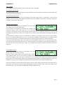
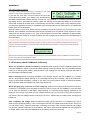
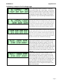
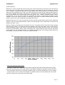
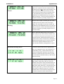
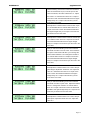
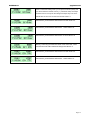
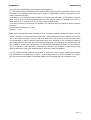
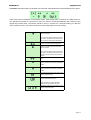
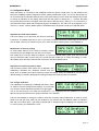
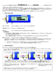
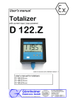
CellMeter-8
ep-plane.com
Thank you for purchasing the CellMeter-8. The CellMeter-8 allows you to check the individual cell voltages of a 2cell8cell LiPo (lithium polymer) battery. The CellMeter-8 individually measures & diagnoses the cell voltages of the multiple
cells, the result is displayed on the large liquid crystal screen.
The CellMeter-8 replaces all of the tedious measurement and calculations required in the past to determine the overall
voltage of the LiPo pack and the individual cell voltages that determine the balance of the LiPo pack.
The CellMeter-8 now makes it possible to determine and verify the detailed state of the LiPo battery.
A balanced battery provides a safer environment when flying. If you know that your cell balance is out you can address
the issue.
The prevention of deteriorating cells over time, will improve the efficiency and stability of the LiPo battery.
1.
CellMeter-8 Applications
1
2
3
LiPo Balance Connector ~ 2-8Cell LiPo
LCD (Liquid Chrystal Display) ~ the battery information is displayed on the LCD screen
Menu Button ~ changes the display between different display readouts. The button also allows
for numeric input in the thrust calculator.
PC Serial connector ~ allows for the connection of a serial cable to a computer. (Not yet implemented). Check website for software updates. http://www.ep-plane.com/cm
4
2.
Basic Use Method
When you connect the balance lead to the Cellmeter-8 you must ensure that both the Ground pin’s for the
balance connector and the Cellmeter-8 go together. Different Balance leads have different wiring configurations and some are coloured (like the samples BELOW).
The Cellmeter-8 has 2.54mm pin intervals. If the connector on you battery does not fit do not force the connector obtain a suitable adaptor lead from your hobby shop.
The LiPo battery balance connector is connected to the “LiPo Balance Connector” on the CellMeter-8
Page 1
CellMeter-8
1.
2.
3.
4.
ep-plane.com
The balance connector of the battery pack is connected
to the LiPo connector of CellMeter-8. The ground pin (the
lowest voltage reference point on the balance connector
0V) connects to the ground pin marked on the CellMeter.
You should hear a short sound, “[stepped beep]” the CellMeter-8 starts, the title picture as in the
top right figure is indicated instantly. If the CellMeter-8 does not start, check the connection of the
battery and the polarity of the balance connector is around the right way. The Total voltage in the
battery pack of an over discharged battery cannot start a
CellMeter-8 if the voltage has fallen below 5V.
After the initial boot up screen as described above the
CellMeter will beep respectively and display the numExample 3 Cell LiPo
ber of cells in the LiPo pack. For example if the LiPo is
a 3 cell pack, the symbols will indicate the number of
cell and you will hear a “blip” 3 times. Please verify by the number indicated on the LCD screen to
the number of actual cells of the battery pack. When the CellMeter displays an incorrect cell count,
you need to verify whether the first connector of the balance connector is connected to the first
position in the Cell Meter. Alternatively there may be a of fault in the battery balance lead or cell
malfunction.
If when you initiate the Cellmeter you are not presented with the main page as in the figure below.
You can return to this page by cycling through the screens by using the menu button.
Serial Pack Voltage
Remaining volts gauge
Remaining amount fuel gauge
The remaining amount gauge gives you a graphical
bar graph display of the status of the battery by graph
and the balance of the cells by graph. When the batCell balance gauge
The number of serial Cells
tery is fully charged the graph extends to “F” on the
Remaining Gauge page example
right hand side of the LCD. As in the example you can
see that the battery is about 50% used. If your battery shows only 1 bar you must charge the battery before
you use it. Each Graphical bar on the Volts gauge refers to about 10% of the overall battery voltage. There
are times when differences occur between the remaining amount and the actual remaining amount. These
difference can be associated with the quality and use of the battery and its cells. A battery that has always
been charged with a reputable balancer is likely to reproduce accurate readings on the CellMeter. A battery
that has had a hard life full discharge and recharge with no balance charging is more likely to have discrepancies between actual and shown results.
Cell balance gauge
The Cell balance gauge measures the difference between all cells that are connected to the CellMeter.
The difference is shown graphically between the cell that is showing the highest cell voltage to the cell that
is showing the lowest cell voltage (largest cell voltage difference) indicated on the graph. When the cell voltages read equal, the bar extends all the way to the right (O). This indicates that the cells are all balanced to
a satisfactory level. When the cells have a difference in voltage the bar shortens and indicates towards the
left (X). The gauge indices are equivalent to 10mV / bar. In order to maintain long lasting battery life if the
balance gauge does not show a satisfactory cell balance then a cell balancer should be applied to the pack
before use. A good cell balancer can be purchased from your local hobby store. If the cell balance indication is low after the battery has been used this can be normal and charging should occur with a balance
charger.
Page 2
CellMeter-8
ep-plane.com
Serial voltage
Pack voltage of the whole battery (total voltage of all cell) is indicated
The number of serial cells
The total number of cells in the battery pack is indicated (3S as indicated in the picture 3 serial cells). This
is the same as the cell quantity.
About the warning function
When there is an abnormality in the cell voltage of the battery pack which is connected, or when the cell
imbalance becomes large (the balance has deteriorated), the CellMeter will display a warning message as
indicated, and an alarm will sounds.
Cell low voltage warning
The Cell Low Voltage Warning is indicated in the case where
the voltage of each cell is under 3.00V.
A LiPo battery cell requires the individual cell voltage to be
maintained above 3.00V. When the cell is not under load
(nothing is connected), and the voltage for the cell has fallen into an overdischarge state, the warning will
be displayed and the alarm will sound. The alarm will continue in this state until the cell voltage rises above
3.00V.
It is important for longevity of your LiPo batteries to maintain a cell voltage over 3.00V even when the battery is in a model and the throttle is on full. If you have the CellMeter connected to the LiPo battery and do
this test on the ground in a controlled environment you will see what the battery is doing under load.
If the cell voltage falls below 3.00V in this test then this indicates the battery is in an over discharge state.
The discharge current which drawn from the cells is too high for this battery. In this case the airplane you
need to look at the power setup of the model. e.g., propeller load could be lowered, would be a good starting point.
Overvoltage warning
The Overcharge Voltage Warning is indicated in the case
where voltage of each cell is too high.
Most LiPo battery pack products in the market have an upper
limit voltage for each cell of 4.20V. Most overvoltage occurs
during the charging cycle. Even then we should try not to exceed 4.25V. when a cell exceeds 4.30V collapse of the cell function starts, when a cell reaches this point ignition / combustion (fire) can occur. The
CellMeter-8 is factory set to trigger the Overvoltage Warning when the cell voltage exceeds 4.24V.
Some LiPo batteries on the market may be able to exceed 4.30V. Always enquire with the manufacturer or
at the place of purchase to ensure that the specifications of the LiPo battery pack. If this is the case for your
LiPo battery then you may wish to increase the warning voltage to 4.35V.
Page 3
CellMeter-8
ep-plane.com
Cell voltage balance warning
The Cell Voltage Balance Warning is indicated in the case
where the cell voltage balance has deteriorated.
If you test the LiPo after a use but before the pack has
cooled down and settled, your reading may be affected as
the balance deteriorates naturally through a cycled run. The CellMeter-8 considering the batteries remaining voltage amount, generates this warning. When this warning occurs allow the battery to cool and then
charge with a balancer and test again. If the Warning occurs when a battery pack is fully charged a balancer should be applied to the pack to re-establish unity across all cells and an even balance. An unbalanced
battery pack can be dangerous.
When the battery check ends, please remove the balance connector from the LiPo connector of the CellMeter-8. If the CellMeter and the battey pack are left connected for a long period of time the there is a possibility that over discharging may occur. (The consumed electric current of the CellMeter-8 is approximately
3mA, but if the pack where for example 1000mAh and was charged fully it would become overdischarge in
about 2 weeks.)
NB: It is possible to make these warning functions invalid. The menu screen shown is activated by holding down the button for 5
seconds, The screen below appears. Clicking the button here, after selecting [No], disable the warning function. Holding down the
button returns to the main menu With this one time warning function disabled, disconnecting and re-connecting the battery resets the CellMeter to the factory default
and the warning function becomes effective again.
3. LiPo battery check CellMeter-8 (reference)
When you purchase a brand-new battery: Immediately after opening it, test the batteries performance
using the CellMeter-8. When an abnormal voltage warning occurs low voltage, there is a possibility that the
battery is an inferior quality battery. Click the button, now showing the cell voltage page and take note of
the cell voltages and balance state.
Before charging: Before connecting the battery to the charger, check it with the CellMeter-8, if it verifies
that an abnormal low voltage warning or an overvoltage warning, this is possibly due to the natural discharge of time whilst the battery is sitting on the shelf. If this occurs either charge or balance the battery
with a reputable balancer/chardger and check again before use.
While charging (only in the case of series charging): When series charging is performed from the main
connectors of the battery pack, the balance terminal is free to connect to the CellMeter-8. This will allow
you to watch the behaviour of the battery whilst charging. It is important whilst charging especially in the
latter half of the charge cycle when the cell voltage becomes high, you will need to verify that the overvoltage warning and cell voltage balance warning do not occur. Please verify the battery after charging and
before use.
After completing the charge: When the batteries voltage reaches 95~100%, it is charged fully? Until it
reaches the overvoltage territory, it isn't overcharged? Has the cell voltage balance been even? And so on
you will need to verify. Several minutes after completing the charge, there are times when the cell voltage
will go down gradually depending upon the battery, after about 10minutes has elapsed from the completion
of charge. Again check using the CellMeter-8 as the reading will be more accurate.
Page 4
CellMeter-8
ep-plane.com
Before the flight: Each time before you fly by habit you should do a battery check verification with the CellMeter-8. This is a good habit to get into as a simple check can save the cost and embarrassment of a
crashed model from the use of a discharged or damaged battery. In addition, using a battery that you know
is fully charged that has decreased naturally between the charge and flight. There is a possibility that the
battery will have deteriorated over time or because it is an older battery.
After the flight: When abnormal voltage warnings occur low voltage warning , over discharge voltage
warning (the current setup is drawing too much power). Post flight you should have a remaining voltage of
about 10%. You should use the remaining battery amount to calculate your next flight times.
Before storing the Battery: If you plan on storing a battery for any reasonable length of time you should
consider the battery charge levels. It is recommended for the Battery to be kept with a 10~20% charge only
in the cells. No more than 50%. This will prevent the battery for over discharging. A new battery off the shelf
from a reputable manufacturer will come with a 50% charge in the battery. If the Battery os less than 10%
charged after a flight then add a small charge before storing. If the battery is fully charged then you can discharge through some battery charger / discharger systems to get the charged state just under 50%.
4. Detailed numerical page
When the button is pressed once from the main page (remaining amount fuel gauge), it changes to the detailed numerical page which can verify the information of the whole battery in summary with detailed values.
The top line shows the serial voltage of the battery at 1mV units, the % indication on the right side of the
screen can verify to 1% units.
On the lower line it shows the cell with the highest voltage on the left and the cell with the lowest voltage to
the right. The voltage difference between the highest cell and the lowest cell is then displayed on the far
right bottom of the display and is accurate to
Remaining amount %
The number of serial cells
Serial voltage
1mV units.
The highest cell voltage
Lowest cell voltage
Cell Voltage differential
Detailed numerical page example
5. Cell voltage page (3 digit (2 decimal point) indication and 4 digit (3 decimal point)
indication)
If you press the button again it changes to the CellMeter-8 voltage page which indicates the individual voltage of all serial cells. On the cell voltage page each serial cell voltage is displayed at 10mV units in a 3 digit
display using 2 decimal places.
Press the button again and you get to the next page where each serial cell voltage is displayed at 1mV
units in a 4 digit display using 3 decimal places. When we verify the cells individual voltage of the LiPo battery, usually it is sufficient in “3 digit indicatory page” of the 10mV unit.
E.g., For the purpose of detailed investigation of the individual cell voltages and the behaviour of the LiPo
battery, perhaps “4 digit indicatory page” is useful.
Page 5
CellMeter-8
ep-plane.com
Whenever the button is clicked, from the “main page” -> the “detailed numerical page” -> the “cell voltage 3
digit indicatory page” -> the “cell voltage 4 digit indicatory page” -> the “main page”… It keeps cycling
through the pages, which ever page in lastly used is the page that is displayed next time the CellMeter-8 is
turn on.
If you are testing a battery with 7 or more cells 7S-8S:
When connecting a battery pack of 7S cells, or more will display on the 4 digit indicatory page only, cell
voltage is indicated but divided into 2 groups. When these are displayed by group this is changed by holding the button down.
Page 6
CellMeter-8
ep-plane.com
Indicatory example of cell voltage page
4S cell, 3 digit page indicatory example of a 4 cell packs.
“The number of serial cells”, “serial voltage”, “the remaining
amount” is indicated in upper row from the left. It shows the
same result as the main page. Individual voltage of each cell
is indicated in the lower position in 3 digits. The numerical
value where the + sign on the left edge is indicates the first
cell.
4S cell, 4 digit page indicatory example of a 4 cell packs. The
information that needs to be displayed for this setup cannot
all be displayed on 1 line, so the first cell voltage is indicated
in place of the remaining voltage % in the upper right side of
the display. In the case of the 2~3 cell pack all cell voltage
are indicated on the lower line and the voltage % remains.
8s cell voltage 3 digit indicatory example of an 8 cell packs.
As with a 5s pack of cells or more, the cell number becomes
more than a row can handle, it reaches the point where both
of the rows are required to be used to indicate all of the cells
voltages. It is recommended to verify this information against
the pack as shown in the “detailed numerical page”.
8s cell voltage 4 digit page indicatory example of 8 cell
packs. When connecting 7 cell or an 8 cell packs, the CellMeter-8 divides all of the cells into 2 groups of 4.The cells
that are at the highest side of the pack closest to the + are
shown and after the cell count will be an (H) indicates the first
4 cell voltages. The indication bars on the display will indicate
4 electric battery bars facing toward 0 direction. When the
button is held, it changes to the indication of the group of the
other side.
8s cell voltage 4 digit page indicatory example of 8 cell
packs. When connecting 7 cell and 8 cell packs, the CellMeter-8 divides all of the cells into 2 groups of 4.The cells
that are at the highest side of the pack closest to the + are
shown and after the cell count will be an (L) indicates the last
3 or 4 cell voltages. The indication bars on the display will
indicate 4 electric battery bars facing toward 0 direction.
When the button is held, it changes to the indication of the
group of the other side.
Page 7
CellMeter-8
ep-plane.com
About the variation of cell voltage
Most of the time you will notice a slight difference between the voltage of the cells in the pack within 10mV (0.01V) .
This becomes more apparent when the pack is under load and has a current running through the cells. This is due to
the variance in capacitance of each cell. The reality is there is no pack that maintains even cell voltage across all
cells under all conditions load or no load from 0%~100% charge. We recommend that the use of a cell balancer be
used when charging to enable the cell voltages to be adjusted to an even level when the pack is fully charged.
When charging a multi cell LiPo battery it is important to always use a balancer and charger or a charger with an inbuilt balancer. There are now many good chargers on the market with built in balancers. Charge times may be longer
using a balancer or a charger with an inbuilt balancer than charging the LiPo with a serial charger only. A balancer or
a charger with inbuilt balancer will continually charge and discharge cells at the end of the main charge cycle to ensure that all cells are equally balanced. If you charge a LiPo only via the serial connector there is a greater risk of
charging the cells to different voltages and causing damage to the cells in the LiPo. A damaged or unbalanced LiPo
is more likely to cause overheating, fire and or damage in or to a model.
If you were to connect the CellMeter-8 as per the diagram below using the CellMeter-8 on the “Cell Voltage Page” you will notice how the individual cells behave under a true load. A good battery will show an
even discharge across all cells under a heavy current load (Discharge).
The image above shows the CellMeter-8 measuring the battery under load. The load is provided by the
speed controller, motor with a propeller and securely fixed to a test station or in a plane.
(The test has been conducted in a controlled environment. Do not attempt to replicate this test without taking due care to secure and
make the test environment safe).
Page 8
CellMeter-8
ep-plane.com
6. Main menu
When you first connect the battery under 7s cells to the CellMeter-8 one of the following pages will be displayed, main page,
the detailed numerical page, the cell voltage 3 digit page or the
cell voltage 4 digit page. To access the Thrust calculator Hold
the button until the image as in the example to the right is displayed. To move the [ ] over the next function press the button. To quickly make a change to the [ ] displayed function hold the button down.
Upper row Alert: This is a one off setting that turns the Alarm off if you are doing diagnostics on a battery
that is triggering the alarm. The Cellmeter-8 will revert back to Alert on when the battery is removed.
You have the choice to turn the Alarm on or off ([Yes] or [No]) to have the Alarm continue while the abnormal voltage is present. The alarm will display a warning message at the time of the cell imbalance. When
[Yes] is selected, the warning message is made with the alarm. Only use the [No] state when you are undergoing diagnostics on a known issue when [No] is selected the warning display and the alarm will
cease. In a state where a cell is over discharged or overcharge the cell is dangerous because the warnings have been stopped. For safety, this setting is not recorded to the CellMeter itself. After removing the
battery pack, connection for the second time the CellMeter restarts.
Lower row ThrustCalc: To activate the Thrust Calc select and hold the button when the [Run] is selected.
If the menu is left up and no button is pressed for 10 seconds a warning beep plays for the last three seconds and the words “cancelled” appear on the screen briefly, the CellMeter-8 resets to the CellMeter main
pages.
7. Thrust portable calculator
With the main menu ThrustCalc: [Run] is selected, byh holding the button down ThrustCalc starts.
Thrust Calc is able to Calculate the following
What can be done with ThrustCalc
(a) propeller revolution rpm (Revolutions Per Minute),
(b) Propeller length,
(c) Propeller pitch
①Thrust from motor
②Brake horsepower (Power)
(d) voltage
(e) Calculated current draw
③Electric power consumption
④Efficiency of the power setup is indicated.
Page 9
CellMeter-8
ep-plane.com
①About thrust:
The CellMeter can estimate the thrust of an aeroplane, there are many variances and some known factors. Lets assume we have an aeroplane and this is its first flight. We know the size of the prop and we
can do a static full throttle rpm check with a tachometer on the ground. We can now add these known
figures into ThrusCalc. By the fact that you can verify thrust it becomes possible, to estimate the general
power of the aeroplane in advance. This will give you more knowledge about your plane and the power
characteristics to make your first flight less challenging and safer, after all you may have other flight characteristics to deal with. This should help you to estimate flight take off distances, recovery from a stall. For
more experienced pilots this will enable them to calculate if the plane is going to be able to hover. It can
show you what changes to the power calculation will be affected by a different size prop.
②About brake horsepower:
Brake horsepower is “the power which is necessary to turn a propeller at a given rpm (propeller has a
known size & pitch). This is indicated in ThrustCalc as a watt value or kilowatt value, but it is “the highest
output and horsepower”. The motors power kW compared with horse power hp is about double. If the
power of a motor in kW is compared with the horsepower of the motor the results are significantly different.
If the watt value of a Motor compared to horse power lets say 1watt. The numerical value which is displayed as power of the motor is 0.00136 times. This has a kilowatt value of 1. Because 36 can convert to
a horsepower value by the fact that it doubles its known watt value at a PS unit, output PS can be compared to the engine and the highest output which is indicated.
In the following case we would like to compare with a hp declared value, and convert with the watt value
×0.00134, or the kilowatt value ×1.34.
(1 W = 0. 136 P S = 0. 134 h p
1 k W = 1. 36 P S = 1. 34 h p
1 P S = 735. 5 W = 0. 7355 k W
1 h p = 745. 7 W= 0. 7457 k W)
③About electric power consumption:
Power is the calculation of Voltage x Current (P=VxI). If there is no voltage present then there are no current (amps) running through the circuit (motor). For a Current to run through a circuit there needs to be a
complete circuit so current can run even if there is no motor present.
Page 10
CellMeter-8
ep-plane.com
④About efficiency:
Efficiency is a ratio of power that is put into the motor versus the amount of power the motor converts into
turning the prop. In an ideal world the motor would achieve 100% efficiency. We know what this is not the
case. In general a smaller say 50g motor will only reproduce about 60% efficiency but a larger motor say
300g can return an efficiency up to 90%. The rest of this energy is turned in heat. When the data sheet for
the motor is available we can do a comparison, it is possible to know the theoretical efficiency values from
there. At full throttle it turns actually power units at the ground, “rpm”, “voltage”, measures “electric current”
simultaneously, by the fact that it inputs into ThrustCalc are known, It now becomes possible to verify
whether or not the two values compare. The efficiency value which ThrustCalc indicates and the general
efficiency value of the motor weight which the graph below shows,
Because some loss occurs even in the electric wire the controller and the like the electric if from theoretical
efficiency value and the general efficiency value in the below graph from the data sheet of the motor the
difference is about +-15%,
Motor Efficiency
When the efficiency indicated by the ThrustCalc-8 is low in comparison with the motor data sheet, perhaps
there are some electric, or mechanical issues somewhere in the power units path / chain, or incorrect propeller size battery voltage. In this case do not fly with this set up, inspect the various parts once more and
look for any abnormalities. “Electric power consumption (W) - brake horsepower (W) = loss (W)” with these
known factors you can calculate the loss, but remember a large portion of the energy has be turned into
heat steadily, in the end can burn out a motor or speed controller. Motor Weight
Thrust Calc Numerical input method
ThrustCalc is divided into 2 pages the thrust brake horsepower page and the electrical efficiency page.
Both allow numerical input in the upper section of the display showing the calculation result in the lower
row of the display. Here the rpm =9,253rpm propeller length =12.0 inch propeller pitch =6.0 inch voltage
=13.60V electric current =45.3A as an example. Try different values so you are familiar with its function
and how it works for the next time you are at the field.
Page 11
CellMeter-8
ep-plane.com
Immediately after starting ThrustCalc the cursor will
appear as an under line under the numerical value of
thousands. (under the 8 in 8000 in this example). If the
Cursor button is pressed for a short interval the cursor will
move to the next numerical value of hundreds and so
on. The values that are set in each location are remembered in the CellMeter8 memory even when the
battery is removed. In order to become proficient with
using the ThrustCalc try practising using the cursor.
When the button is held, ThrustCalc goes into numerical editing mode, the position of the cursor begins
Blinking blinking. The values that are set in each location are
remembered in the CellMeter8 memory even when the
battery is removed. In order to become proficient with
using the ThrustCalc try practising using the cursor to
input some values.
When in Numerical editing mode you can press the
button quickly and you will increase the number count
by 1. (Increment mode) each input increases from 0-9
accept for the Prop, Voltage and Amps they have incremental value of the 0~49. Because we would like to
designate thousand rank of rpm as 9, if the numerical
value which is originally indicated is under 8, it requires several increases by clicking buttons, to get to
9.
Numerical editing menu To edit the numerical value which is originally larger
than 9, or by clicking too much. You can open the numerical editing menu, [-] select with the button and
execute by holding down the button. Now whenever
the button is clicked from the main screen, it is possible to decrease the numerical value by 1 value at time.
(Decrement mode)
You have entered the first numerical value and you are
happy with the valuie and you wish to move to the
hundreds value position. Press and hold the Button for
a couple of seconds you will enter into the numerical
editing menu again. Select the [→] and press and hold
the button again. When you return to the ThrustCalc
main screen you will have moved over 1 unit to the
Hundreds value. Use this method to navigate through
the values to iunput the correct numerical values.
Page 12
CellMeter-8
ep-plane.com
Now the blinking cursor has moved to the numerical
value of hundred rank of rpm, increase up to 9 with
click of the button, this value rotates from 0-1. Adjust
this value to 2. Hold the button down for a couple of
seconds to reach the Numerical Edit Menu and again
straight away for a couple of seconds and you will
move to the next value.
Now adjust the numerical value of the ten rank of rpm
to 5 as described above. Hold the button down for a
couple of seconds to reach the Numerical Edit Menu
and again straight away for a couple of seconds and
you will move to the next value.
Now adjust the numerical value of the unit rank of rpm
to 3. Hold the button down for a couple of seconds to
reach the Numerical Edit Menu and again straight
away for a couple of seconds and you will move to the
next value.
Now you will see the blinking cursor has moved the
numerical unit value to the ten value. This is because
the option in this section will allow you to change the
whole number between 0-49. Change the number to
12. Hold the button down for a couple of seconds to
reach the Numerical Edit Menu and again straight
away for a couple of seconds and you will move to the
next value.
Now adjust the numerical value of 0.1 rank of the propeller length. Adjustment will be from 0-9. Adjust this
value to 0. Hold the button down for a couple of seconds to reach the Numerical Edit Menu and again
straight away for a couple of seconds and you will
move to the next value.
Now you will see the blinking cursor has moved the
numerical unit value to pitch value. Adjustment will be
from 0-9. Change the number to 6. Hold the button
down for a couple of seconds to reach the Numerical
Edit Menu and again straight away for a couple of seconds and you will move to the next value.
Now adjust the numerical value of 0.1 rank of the propeller pitch. Adjustment will be from 0-9. Adjust this
value to 0.
Page 13
CellMeter-8
ep-plane.com
Now you should have the three values as entered into the ThrustCalc on the previous page. The “rpm”
the Propellers “length” and the Propellers “pitch”. These values will be represented on the top row of the
LCD display. On the lower Row of the LCD display you will see the values calculated. Th: 2.0kg
Po:450W. This is what you expect to get as a real value result from a live setup.
Th: (Thrust) numerical value is shown in grams and kilograms. When the value is below 999g it is indicated as a gram value. When the value is higher than 999g it is shown as (k) kilograms and the symbol k
is used.
Po: (out put power) numerical value is shown in Watts and kiloWatts. When the value is below 999W it is
indicated as a Watt value. When the value is higher than 999W it is shown as (k) kilowatt and the symbol
k is used.
If you are only after the thrust and brake horsepower then you are done. You can compare the thrust and
weight of the aeroplane if indicated to the calculated values in ThrustCalc.
If you have the rpm measurement and voltage and electric current, then it is possible to do the efficiency
calculation also.
Reference: You can measure the serial voltage whilst moving the throttle up to full, with the CellMeter-8
connected to the balance port of the LiPo battery. For electric current you can use a DC clamp meter between the battery and the speed controller. Used in conjunction with a WattMeter or other type of measurement tool. You will be able to measure voltage and electric current simultaneously. If you utilise Hyperion’s E-Meter for rpm , voltage and electric current, you will be able to store the values in the e-Meter
memory.
Page 14
CellMeter-8
ep-plane.com
When in Numerical editing mode you can press the button quickly and
you will increase the number count by 1. (Increment mode) each input
increases from 0-9 accept for the Voltage and Amps they have incremental value of the 0~49. Set the tens unit rank value to 1.
Continue as you did before and set the unit rank value to 3.
Continue as you did before and set the .1 rank value to 6.
Continue as you did before and set the .01 rank value to 0.
Now by continuing to utilise the cursor menu move the cursor
over the tens unit value rank and change the value to 4.
Continue as you did before and set the unit rank value to 5.
Continue as you did before and set the .1 rank value to 3.
Page 15
CellMeter-8
ep-plane.com
You have now completed the Input of all values into ThrustCalc.
Pi in the lower position: (InputPower) The numerical value is electric power consumption. When it is below 999W, it is indicated as a watt value, when it is above 1,000W, prefix meaning k is attached, this becomes a kilowatt inscription.
Ef: (Efficiency) The numerical value is efficiency. In regard to the calculation, when efficiency becomes
100% or more, Over is indicated. Because (efficiency over 100% or more is not possible, when Over, is
displayed there is an input error for one or more of the numerical values).
If the data has been input correctly as indicated in the previous pages the following values should be
achieved.
Electric power consumption — 616W
Efficiency — 73%
Note: As for thrust and the brake horsepower which ThrustCalc indicates, because the value is an estimated calculation, the actual thrust may differ from brake horsepower, this may happen because the
pitch is too large or the prop is too long. With a simulation if the rpm is too low this has not been taken
into consideration. In order to obtain the appropriate thrust, it is necessary to use a prop that is inside the
appropriate manufactures range where the propeller designer has specified pitch anti- diamond ratio and
rpm. In addition, actual thrust changes can occur with different atmospheric pressures. As for the simulation of ThrustCalc the APC propeller is optimized as a standard. For propellers of other brand names
there are also some where pitch standards differs, when errors becomes apparent.
You may need to actually measure the propeller as some hub s differ and the measurements change
from manufacturer to manufacturer. (1 inches = approximately 2.54cm) As for the simulation it is not perfect you should be able to obtain a reasonable assessment of the setup that you are wanting to use.
Page 16
CellMeter-8
ep-plane.com
ThrustCalc When the button is held down the numerical value blinkes the numerical editing menu opens. If the cursor menu is left active on the display screen, it will timeout after 10 seconds. If a state where noone operates the button for 10 second or more, the menu is closed automatically and it returns to the
original input mode menu. The buzzer sounds in every 1 seconds for 3 seconds alerting you that the
menu is about to close. You have 3 seconds to react to stop tyhe menu from closing.
Cursor is moved to the next numerical
value to the right. If the cursor is already on the last numerical value in the section it will move to the
next numerical value in the next section.
Cursor is moved to the next input item.
Cursor is moved to the next numerical
value to the left.
If the cursor is already on the last numerical value in the section it will move to the
previous numerical value in the previous
section.
Cursor is moved to the previous input
item.
The numerical value will decrease 1 increment at a time with each click (decrement
mode).
The numerical value will increase 1 increment at a time with each click (increment
mode).
This will reset the value of the cursor highlighted number to zero
Ends numerical editing mode.
Again to enter into numerical editing
mode, the button needs to be held.
ThrustCalc mode ends, and returns to the
battery information page.
Page 17
CellMeter-8
ep-plane.com
8. Configuration Mode
When the battery is connected to the CellMeter-8 while the button is held down. On the release of the
button the CellMeter-8 stats Configuration mode. (setting modification mode). You can by clicking the button scroll through the individual settings and to verify each setting in order. When the setting that you wish
to change is indicated on the display press and hold the button to activate the [ ] (cursors brackets)
around the value that will be changed. Press the button to advance the [ ] value by a +’ve increment of 1.
Hold down the button again and the options page will be displayed. The value can be changed by increments of -1 values, a factory default option is available and an OK option to enter your selected option.
Adjustment of hold time of button
This menu allows you to adjust the click time for the button
to advance. The default hold time is 1sec. If you wish to make the click time 0.5sec input for the ThrustCalc is faster. This may be a better way for you to enter numerical values quicker in the CellMeter-8.
Modification of warning voltage
An Overvoltage warning occurs when the battery voltage
exceeds the pre set voltage level set here in this screen.
Cell voltage such as a LiPo balance problems, if you have a special battery pack which has a limit that
does not exceed 4.300V is used. This is the screen that will enable you to modify this setting. In a standard battery pack where the cells use with 4.240V the standard (default) value.
Adjustment of remaining amount meter
The remaining amount value meter can be adjusted. The
CellMeter-8 calculates the remaining amount from the
value which is added to this value to and the actual cell voltage. When the CellMeter-8 is at the factory
default setting it is 0.000V. Modifying this setting will adjust the remaining amount indication.
Cell voltage calibration
The CellMeter-8 is shipped pre calibrated and there is really
no need for the user to adjust these settings. If you find that
over time the values deteriorate and the errors get bigger.
This is the area that you can make the corrections in. It is suggested that the CellMeter-8 is checked
against a known test device like a quality multimeter / DC voltmeter.
There is the capability to change the offset in each AD converter channel parameter, in order to correct
offset error and gain error these can be modified. If you feel that the Cell Meter-8 needs re calibration
then this can be done upto 1 year after purchase with no charge accept for shipping from ep-plane.com
To confirm pricing for recalibration e-mail.
Page 18
CellMeter-8
ep-plane.com
About Configuration menu
When the numerical value [ ] it is surrounded the menu item you wish to use. .
Note: Please check that the battery has enough battery level to execute the configuration mode before
entering into this mode.
Correction of numerical value is confirmed. Press and
hold the button to execute.
Correction of numerical value is cancelled, resets to
original numerical value. Press and hold the button to
execute.
Correction of numerical value is cancelled, resets to
standard value (factory default). Press
When the [-] is selected hold down the button to reenter the numerical page. You will now be able to
change your numerical value in decreasing values of
1. When in (decrement mode) the condition of [ + ] is
indicated in the menu.
When the [ + ] is selected hold down the button to reenter the numerical page. You will now be able to
change your numerical value in increasing values of 1.
When in (increment mode) the condition of [ - ] is indicated in the menu.
For up to date information on the CellMeter-8. please visit ep-plane.com or email: [email protected]
Page 19