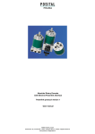
Download absolute inclinometer with device net interface user manual
Transcript
AB SOLUTE I NCLINOMETER W ITH DEVICE NET INT ERFACE
US ER MA NUAL
Version 04/01
UME_ANSD.doc
Contents
Page
1. Introduction......................................................... 1
2. Data Transmission ............................................. 2
2.1. The Object Dictionary...................................... 2
2.2. CAN Identifier Definition .................................. 3
3. Programmable Parameter .................................. 4
4. Operating Mode.................................................. 5
4.1. Polled Mode .................................................... 5
4.2. Change of State Mode..................................... 7
4.3. Saving Parameter............................................ 8
5. Transmission of the actual position .................... 9
6. Installation ........................................................ 10
6.1. Electric connection ........................................ 10
6.2. Settings in the Connection Cap ..................... 11
7. Power On ......................................................... 12
7.1. Operational Status......................................... 12
7.2. Programming................................................. 12
8. Technical Data ................................................. 15
8.1. Electrical Data ............................................... 15
8.2. Mechanical Data............................................ 15
Version 04/01
UME_ANSD.doc
1. Introduction
Absolute inclinometers provide a definite value for
-
Polled Mode
every possible inclinations.
Applications are structural engineering, levelling
-
Change of State
Cyclic Mode
and measuring techniques or inclinations.
The protocol supports the programming of the
The absolute inclinometer has got a maximum
resolution of 45° per each axis. Totally a 2 axis
following additional functions:
Preset value for Axis X
version is available in one housing. A update cycle
time for the inclination is 5 times per second. This
-
Preset value for Axis Y
Out of range measurement detection
depends on the internal measurement principle.
-
Status information
The integrated CAN-Bus interface of the absolute
inclinometer supports all the DeviceNet functions.
The general use of absolute inclinometer with
DeviceNet interface is guaranteed.
The following modes can be programmed and
enabled or disabled:
Version 04/01
page 1 of 16
UME_ANSD.doc
2. Data Transmission
The data transmission in the DeviceNet network is
COB-ID
Message Header
Message Body
realized by message telegrams. Basically, these
telegrams can be divided into the CAN-ID and 8
11 Bit
1 Byte
7 Byte
following bytes as shown in the table below:
2.1. The Object Dictionary
Instance Attribute of the Position Sensor Objects
Class Code:
65 hex
Attribute ID
Access
Name
Data length
Description
65 hex
Get
Number of Attributes
USINT
Number of supported Attributes
66 hex
Get
Attribute
Array of USINT
List of supported Attribute
67 hex
Get
Inclination value
DINT
current inclination
68 hex
Get / Set
Preset Value X-Axis
SINT
setting a defined value
69 hex
Get / Set
Preset Value Y-Axis
SINT
setting a defined value
70 hex
Get / Set
Operating Parameter
BYTE
Out of range
detection
71 hex
Get
Status
BYTE
Status information
Get / Set:
read, write
Version 04/01
page 2 of 16
measurement
UME_ANSD.doc
2.2. CAN Identifier Definition
The inclinometer is a Group 2 Server which uses the Predefined Master/Salve Connection Set.
In the following table a user can see the necessary identifier for communication.
10 9
0
8
7
6
Group 1
5
4
3
2
1 0
Identity
Hex
Usage
Range
Source MAC ID
GROUP 1 Message
000-3ff
Message ID
0
1
1
0
1
Source MAC ID
Slave’s I/O Change of State or Cyclic Message
0
1
1
1
1
Source MAC ID
Slave’s I/O Poll Response or Change of State/Cyclic
Acknowledge Message
1
0
MAC ID
Group 2
GROUP 2 Messages
400 - 5ff
Message
ID
1
0
Destination
ID
MAC 0
1 0
Master’s Change of State or Cyclic Acknowledge
Message
1
0
Source MAC ID
0
1 1
Slave’s Explicit/Unconnected Response Messages
1
0
Destination
MAC 1
0 0
Master’s Explicit Request Message
ID
1
0
Destination
ID
MAC 1
0 1
Master’s I/O Poll Command/Change of State/Cyclic
Message
1
0
Destination
ID
MAC 1
1 0
Group 2 Only Unconnected Explicit Request Message
(reserved)
1
0
Destination
ID
MAC 1
1 1
Duplicate MAC ID Check Messages
Version 04/01
page 3 of 16
UME_ANSD.doc
3. Programmable Parameter
3.1.1. Preset value X-Axis
The preset value is the desired position value,
which should be reached at a certain physical
inclinometer is set to the desired process value by
the parameter preset. The preset value must not
position of the axis. The position value of the
exceed the physical resolution of the sensor.
Attribute ID
Default value
Value range
Data length
68 hex
0 hex
0hex - total measuring range
Signed Integer 16
3.1.2. Preset value Y-Axis
The preset value is the desired position value,
which should be reached at a certain physical
inclinometer is set to the desired process value by
the parameter preset. The preset value must not
position of the axis. The position value of the
exceed the physical resolution of the sensor.
Attribute ID
Default value
Value range
Data length
69 hex
0 hex
0hex - total measuring range
Signed Integer 16
3.1.3. Out of range measurement detection
This feature allows the user to detect an over- or
underrange detection of the measurement value.
When this feature should be activated, the
operating parameter must be configured.
An out of range status is indicated by a status byte
in the I/O connection.
Attribute ID
Default value
Value range
Data length
70 hex
0 hex
0hex - 1hex
BYTE
3.1.4. Status information
This parameter is also transmitted in the I/O
connection. Two flags in the status byte indicates
independently an overrange for each axis.
Attribute ID
Default value
Value range
Data length
71 hex
0 hex
0hex - 3hex
BYTE
Version 04/01
page 4 of 16
UME_ANSD.doc
4. Operating Mode
4.1. Polled Mode
For switching the polled mode on the following
telegrams are needed. Further it is assumed in the
Allocate Master / Slave Connection Set
following example a master MAC ID of 0A hex and
a slave MAC ID of 03 hex.
Allocate Polling
Byte Offset
Bit 7
Bit 6
Bit 5
0
Frag [0]
XID
MAC ID
1
R/R [0]
Service [4B]
Bit 4
Bit 3
Bit 2
Bit 1
Bit 0
Class ID [03]
Instance ID [01]
Allocation Choice [03]
0
0
Allocator MAC ID
CAN Identifier Definition
10
9 8 7 6 5 4 3 2 1 0 Identity
Hex
1
0 Destination MAC 1 1 0 Group 2 Only Unconnected
ID
Message (reserved)
Usage
Range
Explicit
Request
Example:
CAN-ID
Byte 0
Byte 1
Byte 2
Byte 3
Byte 4
Byte 5
41E
0A
4B
03
01
03
0A
Setting the Expected_packet_rate of the Explicit
Message Connection on 0:
CAN Identifier Definition
10
9 8 7 6 5 4 3
2 1 0 Identity
Usage
1
Hex
Range
0 Destination MAC ID 1 0 0 Master’s Explicit Request Message
Version 04/01
page 5 of 16
UME_ANSD.doc
Example:
CAN-ID
Byte 0
Byte 1
Byte 2
Byte 3
Byte 4
Byte 5
Byte 6
41C
0A
10
05
01
09
00
00
Setting the Expected_packet_rate of the Polling
Connection on 0:
Example:
CAN-ID
Byte 0
Byte 1
Byte 2
Byte 3
Byte 4
Byte 5
Byte 6
41C
0A
10
05
02
09
00
00
Release Master / Slave Connection Set
Release Polling
Byte Offset
Bit 7
Bit 6
Bit 5
0
Frag [0]
XID
MAC ID
1
R/R [0]
Service [4C]
Bit 4
Bit 3
Bit 2
Bit 1
Bit 0
Class ID [03]
Instance ID [01]
Release Choice [03]
Example:
CAN-ID
Byte 0
Byte 1
Byte 2
Byte 3
Byte 4
41E
0A
4C
03
01
03
Version 04/01
page 6 of 16
UME_ANSD.doc
4.2. Change of State Mode
The inclinometer is sending without any request
from the host, when the actual process value is
value is not changing. The result is a reduced bus
loading.
changing. No telegram will occur when the position
Allocate Master / Slave Connection Set
1. Allocate COS
Byte Offset
Bit 7
Bit 6
Bit 5
0
Frag [0]
XID
1
R/R [0]
Service [4B]
Bit 4
Bit 3
Bit 2
Bit 1
Bit 0
MAC ID
Class ID [03]
Instance ID [01]
Allocation Choice [51]
0
0
Allocator MAC ID
Example:
CAN-ID
Byte 0
Byte 1
Byte 2
Byte 3
Byte 4
Byte 5
41E
0A
4B
03
01
51
0A
2. Setting Expected_packet_rate of the Explicit
Message Connection on 0:
Example:
CAN-ID
Byte 0
Byte 1
Byte 2
Byte 3
Byte 4
Byte 5
Byte 6
41C
0A
10
05
01
09
00
00
Setting Expected_packet_rate of the Change of
State Connection on 0:
Example:
CAN-ID
Byte 0
Byte 1
Byte 2
Byte 3
Byte 4
Byte 5
Byte 6
41C
0A
10
05
04
09
00
00
Version 04/01
page 7 of 16
UME_ANSD.doc
Release Master / Slave Connection Set
Release COS
Byte Offset
Bit 7
Bit 6
Bit 5
0
Frag [0]
XID
MAC ID
1
R/R [0]
Service [4C]
Bit 4
Bit 3
Bit 2
Bit 1
Bit 0
Class ID [03]
Instance ID [01]
Release Choice [51]
Example:
CAN-ID
Byte 0
Byte 1
Byte 2
Byte 3
Byte 4
41E
0A
4C
03
01
51
4.3. Saving Parameter
The parameter of the inclinometer are saved in a
After successful saving of the parameter the
non-volatile FLASH memory. Because of a limited
number of writing cycles (≈ 1.000), it is useful to
encoder is sending his MAC-ID on the bus. To get
the process value a new allocation of the slave is
transmit the modified parameter in the first step only
in the RAM area. After adjusting and examination
required.
those values should
memory.
be saved in the FLASH
Byte Offset
Bit 7
Bit 6
Bit 5
0
Frag [0]
XID
MAC ID
1
R/R [0]
Service [32]
Bit 4
Bit 3
Bit 2
Bit 1
Bit 0
CAN-ID
Byte 0
Byte 1
Byte 2
Byte 3
41C
0A
32
65
01
Class ID [65]
Instance ID [01]
Example: (MAC-ID Master: 0A hex, MAC-ID Slave:
03 hex)
Version 04/01
page 8 of 16
UME_ANSD.doc
5. Transmission of the actual position
The process value is transmitted according to the
following table.
CAN-ID
process value
X-Axis
Y-Axis
Status
11 Bit
Byte 0
Byte 1
Byte 2
Byte 3
Byte 4
VALUE
27 bis 20
215 bis 28
20bis 27
28bis 215
27 bis 20
Attention: 5°/15° version: resolution 0,001 °, 45°
version: resolution 0,01 °
Status
Bit 7
Bit 6
Bit 5
Bit 4
Bit 3
Bit 2
Bit 1
Bit 0
Flag
0
0
0
0
0
0
Y-Axis Overrange
X-Axis Overrange
Meaning
-
-
-
-
-
-
‘0’ in range
‘0’ in range
‘1’ out of range
‘1’ out of range
‘-’: no meaning, default value
‘0’. Reserved for extensions in future.
Version 04/01
page 9 of 16
UME_ANSD.doc
6. Installation
6.1. Electric connection
The rotary encoder is connected by three cables.
The power supply is achieved with a two-wire
There is a resistor provided in the connection cap,
which must be used as a line termination on the last
connection cable through one PG 9. Each one of
the twisted-pair and shielded bus lines are guided in
device.
and out through two PG 9 on the right side (as seen
on clamps)
Resistor:
Last Device
Device X
57
RT
21
ON
57
21
The
settin
g of
the node number is achieved by 2 turn-switches in
-
G L
78
L
901
23
23
23
78
H G
901
901
78
+
456
456
456
Bd
x10
x1
Clamp
Description
⊥
Ground
+
24 V Supply voltage
-
0 V Supply voltage
CG
CAN Ground
CL
CAN Low
CH
CAN High
CG
CAN Ground
CL
CAN Low
CH
CAN High
Version 04/01
H
the connection cap. Possible addresses lie between
0 and 63 whereby every address can only be used
once. Inside the encoder the defined address is
increased by one. 2 LEDs on the backside of the
connection cap show the operating status of the
encoder.
page 10 of 16
UME_ANSD.doc
6.2. Settings in the Connection Cap
Baudrate in kBit/s
BCD-Drehschalter
BCD coded rotary switches
125
0
250
1
500
2
125
3
reserved
4...9
Bus connection
The connection cap fulfills the function of a Tcoupler. From there the wiring must be done
RT
ON
according to the drawing on the left side. Please
note the assignment of incoming and outgoing bus
signals. An activated bus termination resistor
will lead into a separation of bus in and bus out
+
-
G L
H G
Bus In
Version 04/01
L
H
signals!
Bus Out
page 11 of 16
UME_ANSD.doc
7. Power On
7.1. Operational Status
After power on the inclinometer is sending for twice
times its MAC ID telegram on the bus. Between
Before communication is possible the user must
wait 1 second again after the 2nd MAC-ID check to
each telegram is a defined pause of 1 second. This
behaviour is defined by the DeviceNet protocol.
establish a connection. If the time interval is not
kept the master must try allocation again.
7.2. Programming
If some parameters should not be modified you
could step over this chapter.
The changeable values are written in an italic
spelling.
The following numerical are given in hexadecimal
spelling. In the examples for CAN ID and MAC ID is
Master 0A (hex) and for the slave 03 (hex).
7.2.1. Preset Value for X-Axis
CAN Identifier Definition
10
1
9
0
8
7
6
5
4
3
2
Destination MAC ID
1
Master to Inclinometer:
CAN ID
41C
1
0
0
0
Identity
Hex
Usage
Range
Master’s Explicit Request Message
Set-Parameter
MAC ID
Service Code
Class ID
Instance ID
AttributeID
Byte 0
Byte 1
Byte 2
Byte 3
Byte 4
Byte 5
Byte 6
0A
10
65
01
68
X
X
X: desired Preset Value
Inclinometer to Master:
CAN ID
41B
Version 04/01
Byte 7
Confirmation
MAC ID
Service Code
Byte0
Byte1
0A
90
page 12 of 16
UME_ANSD.doc
7.2.2. Preset Value for Y-Axis
CAN Identifier Definition
10
9
8
7
6
5
4
1
0
Destination MAC ID
3
Master to Inclinometer:
CAN ID
41C
2
1
0
Identity
Usage
Hex
Range
1
0
0
Master’s Explicit Request Message
Set-Parameter
MAC ID
Service Code
Class ID
Instance ID
AttributeID
Byte 0
Byte 1
Byte 2
Byte 3
Byte 4
Byte 5
Byte 6
0A
10
65
01
69
X
X
Byte 7
X: desired Preset Value
Inclinometer to Master:
CAN ID
41B
Confirmation
MAC ID
Service Code
Byte0
Byte1
0A
90
7.2.3. Operating Parameter
Enables the flags in the status byte. In the following table is
listed, which kind of flags can be configured.
Bit 7
Bit 6
Bit 5
Bit 4
Bit 3
Bit 2
Bit 1
Bit 0
0
0
0
0
0
0
0
Overrange Detection for X-/Y-axis
‘0’ no out of range measurement detection activated
‘1’ out of range measurement detection activated
CAN Identifier Definition
10
9
8
1
0
Destination MAC ID
Version 04/01
7
6
5
4
3
2
1
0
Identity
Usage
1
0
0
Master’s Explicit Request Message
page 13 of 16
Hex
Range
UME_ANSD.doc
Master to Inclinometer:
CAN ID
41C
Set-Parameter
MAC ID
Service Code
Class ID
Instance ID
AttributeID
Byte 0
Byte 1
Byte 2
Byte 3
Byte 4
Byte 5
0A
10
65
01
70
X
Byte 6
Byte 7
X: desired Value
Inclinometer to Master:
CAN ID
41B
Confirmation
MAC ID
Service Code
Byte0
Byte1
0A
90
7.2.4. Status Byte
The status byte offers the user very easy detection of alarm
or warning messages. If the inclination sensor is out of range
this is indicated by a flag for each axis. This flag is valid for
under / overflow.
Status
Bit 7
Bit 6
Bit 5
Bit 4
Bit 3
Bit 2
Bit 1
Bit 0
Flag
0
0
0
0
0
0
Y-Axis Overrange
X-Axis Overrange
Meaning
-
-
-
-
-
-
‘0’ in range
‘0’ in range
‘1’ out of range
‘1’ out of range
‘-’: no meaning, default value
‘0’. Reserved for extensions in future.
This information can only be read and is not writeable.
7.2.5. Parameter Saving
Master to Inclinometer:
CAN ID
MAC ID
Byte0
Version 04/01
Set-Parameter
If the transfer has been successful the inclinometer
quotes after 3s with the Duplicate MAC-ID. After
that the master has got to re-allocate the slave.
Service Class
Instance
Code
ID
ID
Byte1
Byte 2
Byte 3
If the transfer is not successful, an error message
will be send. The used service code to save the
32
65
01
parameter set is manufacturer specific.
page 14 of 16
UME_ANSD.doc
8. Technical Data
8.1. Electrical Data
General Layout
according to DIN VDE 0160
Supply Voltage
10 - 30 V DC (absolute limits)
Power Consumption
max. 5 Watt
EMC
electro-magnetical emission according to EN 50 081-2
electro-magnetical compatibility according to EN 50 082-2
Bus connection
galvanically separated by opto-couplings
CAN Transceiver according to ISO/DIS 11898
Resolution
up to 45° degrees
up to 2 axis
Code
Binary
Electrical Lifetime
> 105 h
Baudrate
3 values programmable by 2 rotary-switches
Node Number
programmable by 1 rotary-switch in the connection cap
8.2. Mechanical Data
Housing
Aluminium
Connection
Connection Cap as T-Coupling with clamps
optional: axial connector, D-Sub, 9 pins
Operating temperature
0 ... + 70° C
Storage temperature
-40 ... + 85°C
Humidity
98% (without liquid state)
Degree of protection(EN 60529) Housing
IP 65
Version 04/01
page 15 of 16
UME_ANSD.doc
Imprint
And shall not be liable for any implied warranties of
FRABA POSITAL GmbH
Schanzenstr. 35
merchantability and fitness for a particular purpose
or for any indirect, special, or consequential
D-51063 Köln
Phone
+49 (0) 221-96213-0
damages.
Fax
Internet
+49 (0) 221-96213-20
http://www.posital.de
Alteration of Specifications reserved
Technical specifications, which are described in this
e-mail
[email protected]
manual, are subject to change due to our
permanent strive to improve our products.
Copyright
The company FRABA POSITAL GmbH claims
Document information
copyright on this documentation. It is not allowed to
modify, extend, copy, or hand over to a third party
File name:
Stand:
this documentation without written approval by the
company FRABA POSITAL GmbH Nor is any
Version number: 04/01
Author:
KM
liability assumed for damages resulting from the
use of the information contained herein. Further,
Phone Service
this publication and features described herein are
subject to change without notice.
For technical support, questions and suggestions
for improving our products and documentations call
UME_ANSD.doc
04/03/2001
our telephone line: +49 (0) 221 – 96213-28
Disclaimer of Warranty
FRABA POSITAL GmbH makes no representations
or warranties, either express or implied, by or with
respect
to
Version 04/01
anything
in
this
manual.
page 16 of 16
UME_ANSD.doc


