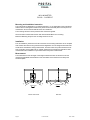
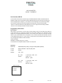
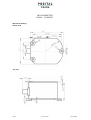
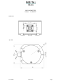
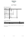
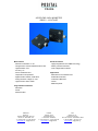
1
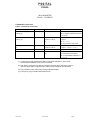
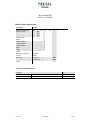
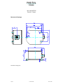
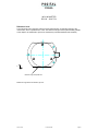
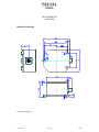
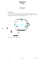
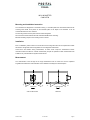
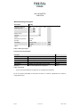
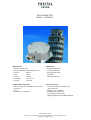
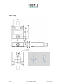
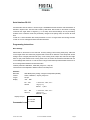
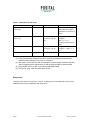
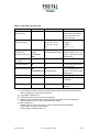
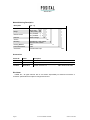
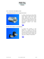
INCLINOMETER RS232 - CURRENT Main Features Applications - Two axis digital inclinometer - Structural engineering - Levelling techniques - Angle measurement range of +/-5°, +/-15° and +/-30°, Resolution up to 0.001° - Measuring techniques - Active linearization and - Inclinations temperaturecompensation - Interface: RS232, Code:ASCII - Mechanical Structure Current 4…20mA 70 mm ∅ - Housing: Programmable Parameters Electrical Features - Transmission mode: Polled Mode, Cyclic Mode - Linear and temperature compensated - Cycle Time - Seting of zero point characteristic line - Microprocessor controlled - Baud-rate 2.4 – 56 KBaud - Polarity inversion protection - Over-voltage-peak protection - Highly integrated circuit in SMD-technology FRABA POSITAL GmbH Schanzenstr. 35, D-51063 Köln, Telefon +49(0)221-96213-0, Telefax +49(0)221-96213-20 www.posital.de, [email protected] INCLINOMETER RS232 - CURRENT Technical Data Electrical Data Model AGS 5 AGS 15 AGS 30 Measuring range +/- 5° +/- 15° +/- 30° Resolution digital 0.001° 0.001° 0.01° Resolution analog 0,001° 0,005° 0,01° Accuracy (T = 0,40° 0 °C .. +55 °C) 0,06° 0,18° Accuracy (T = -25 °C .. +85 °C) 0,12° 0,30° 1,00° Inclination angle in x and y (1) +/-15° +/-40° +/-60° Damping period 5° > 0° typical 1s 10%, 2s 1%, 3s 0.1% Digital interface RS232 format ASCII Baud rate Max. 56 k Analog interface 4...20mA , 0°= 12mA ; Load 300 Ohm Supply voltage (2) 10 - 30 V DC (absolute limits) Current consumption typical 50 mA EMC Emitted interference: EN 61000-6-3 Noise immunity: Electrical lifetime EN 61000-6-2 5 > 10 h (1) Supply voltage is applied. (2) Inclinometers should be connected only to subsequent electronics whose power supplies comply with EN 50178 (protective low voltage) Mechanical Data Housing Aluminum Lifetime > 10 h Shock A=30g; t= 11ms, halfsine ; EN 60068-2-27 Vibration 10 to 150 Hz, 2,5 mm amplitude, 5g const. Acceleration, 5 1 Octave /Minute ; EN 60068-2-6 Weight (standard version) 350 g Environmental Conditions Operating temperature -40°C......+85°C Storage temperature -40°C......+85°C Humidity 98 % (without liquid state) Protection class IP 67 (connected); EN 60529 Page 2 E Info AGS-SC Issue: 01/06 INCLINOMETER RS232 - CURRENT Installation - Electrical Connection The inclinometer is connected via 8 pin round connector or a Cable Connector Assignment Pin Description P8F-Cable CRW-Cable 1 +UB Supply voltage white white 2 RxD brown brown 3 TxD green green 4 Ground (Supply) yellow yellow 5 X-Output grey grey 6 S-Ground pink pink 7 Y-Output blue red 8 red Front view of housing Connector inclinometer output signal (X,Y) analog current 4…20mA (+x,y°... -x,y°) Instructions to mechanically install Do not connect the inclinometer under power! Do not stand on the inclinometer! Avoid mechanical load! Serial Interface RS 232 Communication with the sensor is done through a standardized RS-232 interface. Data transmission is effected in duplex mode. The baud rate is fixed by 9600 baud. After Power On the sensor is sending continuous the angle values in degrees (°). In the setup level several settings can be permanently modified. If the continuous mode was permanently changed to the polling mode, the sensor will send after ”Power On” a start information with actual parameters. On error no angle values are sending and after “Power On” a error message was add to the start information. Issue: 01/06 E Info AGS-SC Page 3 INCLINOMETER RS232 - CURRENT Mechanical Drawings Dimension housing (mm) Page 4 E Info AGS-SC Issue: 01/06 INCLINOMETER RS232 - CURRENT Reference Level The Inclinometer has a mounting reference angel (black line)for an optimal mounting of the inclinometer, which is parallel to the x-axis. This reference angle must be placed exactly parallel to the object to be measured to prevent or minimize any mechanical offset/cross sensitivity. Y X Reference edge, base plate side Reference angle of the inclinometer, top view Issue: 01/06 E Info AGS-SC Page 5 INCLINOMETER RS232 - CURRENT Mounting and Installation Instruction The inclinometer is designed for a horizontal mounting, i.e. the base plate of the inclinometer with the three mounting holes needs to be placed on the horizontal plane of the object to be measured. It can be mounted with M4 screw as a maximum. The mounting surface must be plane and free of dust and grease. We recommend cheese head screws with metrical thread M4 for the mounting. Maximum fastening torque for the mounting screws is 10 Nm. Installation Prior to installation, please check for all connection and mounting instructions to be complied with. Please also observe the general rules and regulations on low voltage technical devices. Avoid shock and vibration during measurement, as these could corrupt the measurement results. Inclination sensors that base on a fluidic measurement principle are optimal for static measurements and suitable to only a limited extent of dynamic measurement. Measurement The measurement of the tilt angle of the single measurement axis is carried out over the respective longitudinal and lateral axis of the inclination sensor. Reference is always the horizontal plane. -y +y -x Lateral axis View of male socket Page 6 Longitudinal axis +x Side view E Info AGS-SC Issue: 01/06 INCLINOMETER RS232 - CURRENT Models/Ordering Description Description Type Key Absolute inclinometer AGS Measuring range . . . -2-S . 1- H0- ... - 005 015 030 Number of axis RS232 without interface O Voltage interface V Current interface C PWM P Switch S Version Mechanical construction Horizontal Dynamic 2 mPas Connection plug, 8 pins P8M 1 m cable exit CRW Option - Accessories and Documentation Description Type Connector, counterpart 8 pins P8F Cable STK 8, 2m, Plug P8F P8F-STK8.2 STK 8, 5m, Plug P8F P8F-STK8.5 Issue: 01/06 E Info AGS-SC Page 7 INCLINOMETER RS232 - CURRENT Serial Interface RS 232 Communication with the sensor is done through a standardized RS-232 interface. Data transmission is effected in duplex mode. The baud rate is fixed by 9600 baud. After Power On the sensor is sending continuous the angle values in degrees (°). In the setup level several settings can be permanently modified. If the continuous mode was permanently changed to the polling mode, the sensor will send after ”Power On” a start information with actual parameters. On error no angle values are sending and after “Power On” a error message was add to the start information. Programming Instructions Basic Settings After Power On, the sensor is in the user level. In factory setting (==Free running mode) every 100ms the current angle values are continuously supplied with a baud rate of 9600 bd. In the Setup-level several settings can be changed permanent like query or free running mode, output rate, baud rate and angle offset. If query mode instead of free running mode is ser, the sensor will send start information with the current settings after Power On. In case of errors no angle values will be provided and after Power On an error message will be added to the start information. Interface parameter: 9600 Baud , 8 data bits, parity even, 1 stop bit, The baud rate can be adjusted to different values in the Setup-level. Structure: Baud rate: 9600 Baud (factory setting, changes in Setup-Mode possible) Format: ASCII, 8 data bits, 1 stop bit, parity even Length: 22 byte Display: <D0 ... D21> D0 ... D10 = “X=±xx.xxx“, <CR>, <LF> with D2 = sign (+ or -) with D5 = point D11 ... D21 = “Y=±xx.xxx“, <CR>, <LF> with D13 = sign (+ or -) with D16 = point display example: … X=+00.430 Y=-00.084 … Page 8 E Info AGS-SC Issue: 01/06 INCLINOMETER RS232 - CURRENT Commands in user level Table 1: instructions at user level instruction to the sensor response sensor explanation activate temporary polling ”f” “f“ the continuous sending of angle val- mode (1) (2) ues are stopped, instructions can send to the sensor activate temporary continuous ”F” mode (1 ) (2) „X=±xx.xxx“, CR, LF, X angle in ° ”Y=±xx.xxx“, CR, LF, Y angle in ° ”X= with „±” = „+“ or „-“, ... one string contains x and y value read angle values at one-time ”R” (3) “X=±xx.xxx“, CR, LF, X angle in ° ”Y=±xx.xxx“, CR, LF, Y angle in ° with „±” = „+“ or „-“ switch to the setup level (3) (4) ”prog” ”P“ Sensor is at setup level show active level (3) “*“ “Ux“ or „U“ means Sensor is at User level ”Sx“ „S“ means Setup-level is active, with „x“ Output-Mode of Sensors „U“ / „I“ / „P“ / „S“ (1) In free running mode measurement data is continuously displayed. In query mode measurement and display is only once on command. (2) After reset or new Power On after an interruption of power supply, the sensor will be in user-level again with the original setup or with the setup changed in the setup level. (3) Only possible in query mode (=free running mode deactivated). (4) The Input of „prog“ must take place within 20 sec. Issue: 01/06 E Info AGS-SC Page 9 INCLINOMETER RS232 - CURRENT Setup Level The Setup level is active until ”Power On” or Reset. All settings taken in the setup level are stored in the EEPROM and permanent available also after Power down. Table 2: instructions at setup level instruction to the sensor response sensor explanation activate permanent “f“ “f“ the continuous sending of angle values are polling mode (1) activate permanent permanent stopped, instructions can send to the sensor “F“ continuous mode (1) continuous sending of „X=±xx.xxx“, CR, LF, X angle in ° ”Y=±xx.xxx“, CR, LF, Y angle in ° ”X= with „±” = „+“ or „-“ ... set rate of data trans- “O“ “O” Echo, mission for continuous mode (2) (3) (4) <Code transmission rate> <Code transmission rate> Code transmission rate or „E“ for Error, if the code is outside defined values read angle values at “R“ same as at user level one-time (2) read version (2) “V“ “AGSxxx-2-Sx“, CR, LF type of Sensor ”SN:xxxx-xxx“, CR, LF ”HV:xx.x“ , CR, LF serial number HW Version internal sensor ”SV:xx.x“ , CR, LF SW Version offset adjust of the “n“ “n“ the actual angle of specified axis is set to specified axis (2) (3) ”x“ or ”y“ ”OffsetX=±xx.xxx“ or ”OffsetY=±xx.xxx“ zero, ±xx.xxx is the internal offset in degree reset offset adjust (2) (3) “N“ “N“ the offset adjust was reset to the original value Set Baud rate (2) (3) (6) “B“ “B“ Echo, Code Baud rate or „E“ for Error, if <Code Baud rate> <Code Baud rate> the code is outside defined values Set switch angle for one “Sx“ Echo, switch angle or „E“ for Error, if the axis (2) (3) (7) (8) <switch angle> or <switch angle> “Sy“ “Sx“ or “Sy” angle is outside admissible range <switch angle> Set hysteresis for “Sh“ “Sh“ Echo, hysterese or „E“ for Error, if the switching point in both <hysterese> <hysterese> angle is outside admissible range “q“ Software-Reset will be executed axis (2) (3) (7) (9) show active level (2) “*“ Reset (2) “q“ Page 10 same as at user level E Info AGS-SC Issue: 01/06 INCLINOMETER RS232 - CURRENT instructions at setup level (1) in the continuous mode the sensor is sending continuous angle values, in the polling mode the sensor is sending one answer after an instruction (2) only possible at polling mode. (3) for activating a reset or power fail restart is necessary (4) for Code transmission rate see (5) Table 3 <Code transmission rate > (6) for Code baud rate see Table 5 <Code Baud rate> Attention! A reset of the baud rate to a default value is not possible. If the user forgets the adjusted baud rate, the new value must be detected by testing. (7) this instruction is only effectual at sensors with switch output, (8) <switch angle>: three digits from “001” until “300” for the angle in tenths of a degree, max working range of the sensor. Default value is 025 == 2,5° (9) <hysterese>: two digits from “01” until “99” for the stitching hysterese in tenths of a degree, max working range of the sensor , Default value is 01 == 0,1° Table 4 <Code transmission rate > <Code rate > transmission strings per second, 1 string contains x and y-value “0“ reserved “1“ 25 Strings/s (10) “2“ 10 Strings/s, Default value (11) “3“ 5 Strings/s “4“ 2 Strings/s “5“ 1 Strings/s “6“ 0,2 Strings/s “7“ 0,1 Strings/s “8“, “9” not defined (10) only allowed with baud rate of at least 9600 Bd (11) only allowed with baud rate of at least 4800 Bd Table 5 <Code Baud rate> <Code Baud rate> baud rate “0“ 2400 Baud “1“ 4800 Baud “2“ 9600 Baud, Default value “3“ 19200 Baud “4“ 38400 Baud “5“ 57600 Baud “6“, “7“, ”8“, ”9“ not defined Issue: 01/06 E Info AGS-SC Page 11 INCLINOMETER RS232 - CURRENT Example for setting the output rate In the following example the output rate is set to 1 string per second instruction to the sensor response sensor explanation „X=±xx.xxx“, CR, LF, continuous sending of angles ”Y=±xx.xxx“, CR, LF, ”X= activate temporary ”f” ... “f“ the continuous sending of angle values are polling mode switch to the setup stopped, instructions can send to the sensor ”prog” ”P“ Sensor is at setup level “O5“ “O5” Code transmission rate is set to 1Strings/s “q“ “q“ Software-Reset will be executed, the new level set rate of data transmission for continuous mode Reset settings are guilty „X=±xx.xxx“, CR, LF, continuous sending of angles at ”Y=±xx.xxx“, CR, LF, ”X= . . . 1 Strings/s We do not assume responsibility for technical inaccuracies or omissions. Specifications are subject to change without notice. Page 12 E Info AGS-SC Issue: 01/06 INCLINOMETER RS232 - VOLTAGE Main Features Applications - Two axis digital inclinometer - Structural engineering - Levelling techniques - Angle measurement range of +/-5°, +/-15° and +/-30°, Resolution up to 0.001° - Measuring techniques - Active linearization and - Inclinations temperaturecompensation - Interface: RS232, Code:ASCII - Mechanical Structure Voltage, 0,5..4,5V 70 mm ∅ - Housing: Programmable Parameters Electrical Features - Transmission mode: Polled Mode, Cyclic Mode - Linear and temperature compensated - Cycle Time - Seting of zero point characteristic line - Microprocessor controlled - Baud-rate 2.4 – 56 KBaud - Polarity inversion protection - Over-voltage-peak protection - Highly integrated circuit in SMD-technology FRABA POSITAL GmbH Schanzenstr. 35, D-51063 Köln, Telefon +49(0)221-96213-0, Telefax +49(0)221-96213-20 www.posital.de, [email protected] INCLINOMETER RS232 - VOLTAGE Technical Data Electrical Data Model AGS 5 AGS 15 AGS 30 Measuring range +/- 5° +/- 15° +/- 30° Resolution digital 0.001° 0.001° 0.01° Resolution analog 0,001° 0,005° 0,01° Accuracy (T = 0,40° 0 °C .. +55 °C) 0,06° 0,18° Accuracy (T = -25 °C .. +85 °C) 0,12° 0,30° 1,00° Inclination angle in x and y (1) +/-15° +/-40° +/-60° Damping period 5° > 0° typical 1s 10%, 2s 1%, 3s 0.1% Digital interface RS232 format ASCII Baud rate Max. 56 k Analog interface 0,5...4,5V , 0° = 2.5V; 1mA Supply voltage (2) 10 - 30 V DC (absolute limits) Current consumption typical 50 mA EMC Emitted interference: EN 61000-6-3 Noise immunity: Electrical lifetime EN 61000-6-2 5 > 10 h (1) Supply voltage is applied. (2) Inclinometers should be connected only to subsequent electronics whose power supplies comply with EN 50178 (protective low voltage) Mechanical Data Housing Aluminum Lifetime > 10 h Shock A=30g; t= 11ms, halfsine ; EN 60068-2-27 Vibration 10 to 150 Hz, 2,5 mm amplitude, 5g const. Acceleration, 5 1 Octave /Minute ; EN 60068-2-6 Weight (standard version) 350 g Environmental Conditions Operating temperature -40°C......+85°C Storage temperature -40°C......+85°C Humidity 98 % (without liquid state) Protection class IP 67 (connected); EN 60529 Page 2 E Info AGS-SV Issue: 01/06 INCLINOMETER RS232 - VOLTAGE Installation - Electrical Connection The inclinometer is connected via 8 pin round connector or a Cable Connector Assignment Pin Description P8F-Cable CRW-Cable 1 +UB Supply voltage white white 2 RxD brown brown 3 TxD green green 4 Ground (Supply) yellow yellow 5 X-Output grey grey 6 S-Ground pink pink 7 Y-Output blue red 8 red output signal (X,Y) 0,5...4,5V (-x,y°... + x,y°) Front view of housing Connector inclinometer Instructions to mechanically install Do not connect the inclinometer under power! Do not stand on the inclinometer! Avoid mechanical load! Serial Interface RS 232 Communication with the sensor is done through a standardized RS-232 interface. Data transmission is effected in duplex mode. The baud rate is fixed by 9600 baud. After Power On the sensor is sending continuous the angle values in degrees (°). In the setup level several settings can be permanently modified. If the continuous mode was permanently changed to the polling mode, the sensor will send after ”Power On” a start information with actual parameters. On error no angle values are sending and after “Power On” a error message was add to the start information. Issue: 01/06 E Info AGS-SV Page 3 INCLINOMETER RS232 - VOLTAGE Mechanical Drawings Dimension housing (mm) Page 4 E Info AGS-SV Issue: 01/06 INCLINOMETER RS232 - VOLTAGE Reference Level The Inclinometer has a mounting reference angel (black line)for an optimal mounting of the inclinometer, which is parallel to the x-axis. This reference angle must be placed exactly parallel to the object to be measured to prevent or minimize any mechanical offset/cross sensitivity. Y X Reference edge, base plate side Reference angle of the inclinometer, top view Issue: 01/06 E Info AGS-SV Page 5 INCLINOMETER RS232 - VOLTAGE Mounting and Installation Instruction The inclinometer is designed for a horizontal mounting, i.e. the base plate of the inclinometer with the three mounting holes needs to be placed on the horizontal plane of the object to be measured. It can be mounted with M4 screw as a maximum. The mounting surface must be plane and free of dust and grease. We recommend cheese head screws with metrical thread M4 for the mounting. Maximum fastening torque for the mounting screws is 10 Nm. Installation Prior to installation, please check for all connection and mounting instructions to be complied with. Please also observe the general rules and regulations on low voltage technical devices. Avoid shock and vibration during measurement, as these could corrupt the measurement results. Inclination sensors that base on a fluidic measurement principle are optimal for static measurements and suitable to only a limited extent of dynamic measurement. Measurement The measurement of the tilt angle of the single measurement axis is carried out over the respective longitudinal and lateral axis of the inclination sensor. Reference is always the horizontal plane. -y +y -x Lateral axis View of male socket Page 6 Longitudinal axis +x Side view E Info AGS-SV Issue: 01/06 INCLINOMETER RS232 - VOLTAGE Models/Ordering Description Description Type Key Absolute inclinometer AGS Measuring range . . . -2-S . 1- H0- ... - 005 015 030 Number of axis RS232 without interface O Voltage interface V Current interface C PWM P Switch S Version Mechanical construction Horizontal Dynamic 2 mPas Connection plug, 8 pins P8M 1 m cable exit CRW Option - Accessories and Documentation Description Type Connector, counterpart 8 pins P8F Cable STK 8, 2m, Plug P8F P8F-STK8.2 STK 8, 5m, Plug P8F P8F-STK8.5 Issue: 01/06 E Info AGS-SV Page 7 INCLINOMETER RS232 - VOLTAGE Serial Interface RS 232 Communication with the sensor is done through a standardized RS-232 interface. Data transmission is effected in duplex mode. The baud rate is fixed by 9600 baud. After Power On the sensor is sending continuous the angle values in degrees (°). In the setup level several settings can be permanently modified. If the continuous mode was permanently changed to the polling mode, the sensor will send after ”Power On” a start information with actual parameters. On error no angle values are sending and after “Power On” a error message was add to the start information. Programming Instructions Basic Settings After Power On, the sensor is in the user level. In factory setting (==Free running mode) every 100ms the current angle values are continuously supplied with a baud rate of 9600 bd. In the Setup-level several settings can be changed permanent like query or free running mode, output rate, baud rate and angle offset. If query mode instead of free running mode is ser, the sensor will send start information with the current settings after Power On. In case of errors no angle values will be provided and after Power On an error message will be added to the start information. Interface parameter: 9600 Baud , 8 data bits, parity even, 1 stop bit, The baud rate can be adjusted to different values in the Setup-level. Structure: Baud rate: 9600 Baud (factory setting, changes in Setup-Mode possible) Format: ASCII, 8 data bits, 1 stop bit, parity even Length: 22 byte Display: <D0 ... D21> D0 ... D10 = “X=±xx.xxx“, <CR>, <LF> with D2 = sign (+ or -) with D5 = point D11 ... D21 = “Y=±xx.xxx“, <CR>, <LF> with D13 = sign (+ or -) with D16 = point display example: … X=+00.430 Y=-00.084 … Page 8 E Info AGS-SV Issue: 01/06 INCLINOMETER RS232 - VOLTAGE Commands in user level Table 1: instructions at user level instruction to the sensor response sensor explanation activate temporary polling ”f” “f“ the continuous sending of angle val- mode (1) (2) ues are stopped, instructions can send to the sensor activate temporary continuous ”F” mode (1 ) (2) „X=±xx.xxx“, CR, LF, X angle in ° ”Y=±xx.xxx“, CR, LF, Y angle in ° ”X= with „±” = „+“ or „-“, ... one string contains x and y value read angle values at one-time ”R” (3) “X=±xx.xxx“, CR, LF, X angle in ° ”Y=±xx.xxx“, CR, LF, Y angle in ° with „±” = „+“ or „-“ Sensor is at setup level switch to the setup level (3) (4) ”prog” ”P“ show active level (3) “*“ “Ux“ or „U“ means Sensor is at User level ”Sx“ „S“ means Setup-level is active, with „x“ Output-Mode of Sensors „U“ / „I“ / „P“ / „S“ (1) In free running mode measurement data is continuously displayed. In query mode measurement and display is only once on command. (2) After reset or new Power On after an interruption of power supply, the sensor will be in user-level again with the original setup or with the setup changed in the setup level. (3) Only possible in query mode (=free running mode deactivated). (4) The Input of „prog“ must take place within 20 sec. Issue: 01/06 E Info AGS-SV Page 9 INCLINOMETER RS232 - VOLTAGE Setup Level The Setup level is active until ”Power On” or Reset. All settings taken in the setup level are stored in the EEPROM and permanent available also after Power down. Table 2: instructions at setup level instruction to the sensor response sensor explanation activate permanent “f“ “f“ the continuous sending of angle values are polling mode (1) activate permanent permanent stopped, instructions can send to the sensor “F“ continuous mode (1) continuous sending of „X=±xx.xxx“, CR, LF, X angle in ° ”Y=±xx.xxx“, CR, LF, Y angle in ° ”X= with „±” = „+“ or „-“ ... set rate of data trans- “O“ “O” Echo, mission for continuous mode (2) (3) (4) <Code transmission rate> <Code transmission rate> Code transmission rate or „E“ for Error, if the code is outside defined values read angle values at “R“ same as at user level one-time (2) read version (2) “V“ “AGSxxx-2-Sx“, CR, LF type of Sensor ”SN:xxxx-xxx“, CR, LF ”HV:xx.x“ , CR, LF serial number HW Version internal sensor ”SV:xx.x“ , CR, LF SW Version offset adjust of the “n“ “n“ the actual angle of specified axis is set to specified axis (2) (3) ”x“ or ”y“ ”OffsetX=±xx.xxx“ or ”OffsetY=±xx.xxx“ zero, ±xx.xxx is the internal offset in degree reset offset adjust (2) (3) “N“ “N“ the offset adjust was reset to the original value Set Baud rate (2) (3) (6) “B“ “B“ Echo, Code Baud rate or „E“ for Error, if <Code Baud rate> <Code Baud rate> the code is outside defined values Set switch angle for one “Sx“ Echo, switch angle or „E“ for Error, if the axis (2) (3) (7) (8) <switch angle> or <switch angle> “Sy“ “Sx“ or “Sy” angle is outside admissible range <switch angle> Set hysteresis for “Sh“ “Sh“ Echo, hysterese or „E“ for Error, if the switching point in both <hysterese> <hysterese> angle is outside admissible range “q“ Software-Reset will be executed axis (2) (3) (7) (9) show active level (2) “*“ Reset (2) “q“ Page 10 same as at user level E Info AGS-SV Issue: 01/06 INCLINOMETER RS232 - VOLTAGE instructions at setup level (1) in the continuous mode the sensor is sending continuous angle values, in the polling mode the sensor is sending one answer after an instruction (2) only possible at polling mode. (3) for activating a reset or power fail restart is necessary (4) for Code transmission rate see (5) Table 3 <Code transmission rate > (6) for Code baud rate see Table 5 <Code Baud rate> Attention! A reset of the baud rate to a default value is not possible. If the user forgets the adjusted baud rate, the new value must be detected by testing. (7) this instruction is only effectual at sensors with switch output, (8) <switch angle>: three digits from “001” until “300” for the angle in tenths of a degree, max working range of the sensor. Default value is 025 == 2,5° (9) <hysterese>: two digits from “01” until “99” for the stitching hysterese in tenths of a degree, max working range of the sensor , Default value is 01 == 0,1° Table 4 <Code transmission rate > <Code rate > transmission strings per second, 1 string contains x and y-value “0“ reserved “1“ 25 Strings/s (10) “2“ 10 Strings/s, Default value (11) “3“ 5 Strings/s “4“ 2 Strings/s “5“ 1 Strings/s “6“ 0,2 Strings/s “7“ 0,1 Strings/s “8“, “9” not defined (10) only allowed with baud rate of at least 9600 Bd (11) only allowed with baud rate of at least 4800 Bd Table 5 <Code Baud rate> <Code Baud rate> baud rate “0“ 2400 Baud “1“ 4800 Baud “2“ 9600 Baud, Default value “3“ 19200 Baud “4“ 38400 Baud “5“ 57600 Baud “6“, “7“, ”8“, ”9“ not defined Issue: 01/06 E Info AGS-SV Page 11 INCLINOMETER RS232 - VOLTAGE Example for setting the output rate In the following example the output rate is set to 1 string per second instruction to the sensor response sensor explanation „X=±xx.xxx“, CR, LF, continuous sending of angles ”Y=±xx.xxx“, CR, LF, ”X= activate temporary ”f” ... “f“ the continuous sending of angle values are polling mode switch to the setup stopped, instructions can send to the sensor ”prog” ”P“ Sensor is at setup level “O5“ “O5” Code transmission rate is set to 1Strings/s “q“ “q“ Software-Reset will be executed, the new level set rate of data transmission for continuous mode Reset settings are guilty „X=±xx.xxx“, CR, LF, continuous sending of angles at ”Y=±xx.xxx“, CR, LF, ”X= . . . 1 Strings/s We do not assume responsibility for technical inaccuracies or omissions. Specifications are subject to change without notice. Page 12 E Info AGS-SV Issue: 01/06 INCLINOMETER RS232 - PW M Main Features Applications - Two axis digital inclinometer - Structural engineering - Levelling techniques - Angle measurement range of +/-5°, +/-15° and +/-30°, Resolution up to 0.001° - Measuring techniques - Active linearization and - Inclinations temperaturecompensation - Interface: RS232, Code:ASCII - Mechanical Structure PWM 1 KHz 70 mm ∅ - Housing: Programmable Parameters Electrical Features - Transmission mode: Polled Mode, Cyclic Mode - Linear and temperature compensated - Cycle Time - Seting of zero point characteristic line - Microprocessor controlled - Baud-rate 2.4 – 56 KBaud - Polarity inversion protection - Over-voltage-peak protection - Highly integrated circuit in SMD-technology FRABA POSITAL GmbH Schanzenstr. 35, D-51063 Köln, Telefon +49(0)221-96213-0, Telefax +49(0)221-96213-20 www.posital.de, [email protected] INCLINOMETER RS232 - PW M Technical Data Electrical Data Model AGS 5 AGS 15 AGS 30 Measuring range +/- 5° +/- 15° +/- 30° Resolution digital 0.001° 0.001° 0.01° Resolution PWM 0,001° 0,005° 0,01° 0,40° Accuracy (T = 0 °C .. +55 °C) 0,06° 0,18° Accuracy (T = -25 °C .. +85 °C) 0,12° 0,30° 1,00° Inclination angle in x and y (1) +/-15° +/-40° +/-60° Damping period 5° > 0° typical 1s 10%, 2s 1%, 3s 0.1% Digital interface RS232 format ASCII Baud rate Max. 56 k PWM interface 1KHz, 20%…80% Supply voltage (2) 10 - 30 V DC (absolute limits) Current consumption typical 50 mA EMC Emitted interference: EN 61000-6-3 Noise immunity: Electrical lifetime EN 61000-6-2 5 > 10 h (1) Supply voltage is applied. (2) Inclinometers should be connected only to subsequent electronics whose power supplies comply with EN 50178 (protective low voltage) Mechanical Data Housing Aluminum Lifetime > 10 h Shock A=30g; t= 11ms, halfsine ; EN 60068-2-27 Vibration 10 to 150 Hz, 2,5 mm amplitude, 5g const. Acceleration, 5 1 Octave /Minute ; EN 60068-2-6 Weight (standard version) 350 g Environmental Conditions Operating temperature -40°C......+85°C Storage temperature -40°C......+85°C Humidity 98 % (without liquid state) Protection class IP 67 (connected); EN 60529 Page 2 E Info AGS-SP Issue: 01/06 INCLINOMETER RS232 - PW M Installation - Electrical Connection The inclinometer is connected via 8 pin round connector or a Cable Connector Assignment Pin Description P8F-Cable CRW-Cable 1 +UB Supply voltage white white 2 RxD brown brown 3 TxD green green 4 Ground (Supply) yellow yellow 5 X-Output grey grey 6 S-Ground pink pink 7 Y-Output blue red 8 red output signal (X,Y) PWM 1 KHz, 20%...80% (-x,y°... +x,y°) Front view of housing Connector inclinometer Instructions to mechanically install Do not connect the inclinometer under power! Do not stand on the inclinometer! Avoid mechanical load! Serial Interface RS 232 Communication with the sensor is done through a standardized RS-232 interface. Data transmission is effected in duplex mode. The baud rate is fixed by 9600 baud. After Power On the sensor is sending continuous the angle values in degrees (°). In the setup level several settings can be permanently modified. If the continuous mode was permanently changed to the polling mode, the sensor will send after ”Power On” a start information with actual parameters. On error no angle values are sending and after “Power On” a error message was add to the start information. Issue: 01/06 E Info AGS-SP Page 3 INCLINOMETER RS232 - PW M Mechanical Drawings Dimension housing (mm) Page 4 E Info AGS-SP Issue: 01/06 INCLINOMETER RS232 - PW M Reference Level The Inclinometer has a mounting reference angel (black line)for an optimal mounting of the inclinometer, which is parallel to the x-axis. This reference angle must be placed exactly parallel to the object to be measured to prevent or minimize any mechanical offset/cross sensitivity. Y X Reference edge, base plate side Reference angle of the inclinometer, top view Issue: 01/06 E Info AGS-SP Page 5 INCLINOMETER RS232 - PW M Mounting and Installation Instruction The inclinometer is designed for a horizontal mounting, i.e. the base plate of the inclinometer with the three mounting holes needs to be placed on the horizontal plane of the object to be measured. It can be mounted with M4 screw as a maximum. The mounting surface must be plane and free of dust and grease. We recommend cheese head screws with metrical thread M4 for the mounting. Maximum fastening torque for the mounting screws is 10 Nm. Installation Prior to installation, please check for all connection and mounting instructions to be complied with. Please also observe the general rules and regulations on low voltage technical devices. Avoid shock and vibration during measurement, as these could corrupt the measurement results. Inclination sensors that base on a fluidic measurement principle are optimal for static measurements and suitable to only a limited extent of dynamic measurement. Measurement The measurement of the tilt angle of the single measurement axis is carried out over the respective longitudinal and lateral axis of the inclination sensor. Reference is always the horizontal plane. -y +y -x Lateral axis View of male socket Page 6 Longitudinal axis +x Side view E Info AGS-SP Issue: 01/06 INCLINOMETER RS232 - PW M Models/Ordering Description Description Type Key Absolute inclinometer AGS Measuring range . . . -2-S . 1- H0- ... - 005 015 030 Number of axis RS232 without interface O Voltage interface V Current interface C PWM P Switch S Version Mechanical construction Horizontal Dynamic 2 mPas Connection plug, 8 pins P8M 1 m cable exit CRW Option - Accessories and Documentation Description Type Connector, counterpart 8 pins P8F Cable STK 8, 2m, Plug P8F P8F-STK8.2 STK 8, 5m, Plug P8F P8F-STK8.5 Issue: 01/06 E Info AGS-SP Page 7 INCLINOMETER RS232 - PW M Serial Interface RS 232 Communication with the sensor is done through a standardized RS-232 interface. Data transmission is effected in duplex mode. The baud rate is fixed by 9600 baud. After Power On the sensor is sending continuous the angle values in degrees (°). In the setup level several settings can be permanently modified. If the continuous mode was permanently changed to the polling mode, the sensor will send after ”Power On” a start information with actual parameters. On error no angle values are sending and after “Power On” a error message was add to the start information. Programming Instructions Basic Settings After Power On, the sensor is in the user level. In factory setting (==Free running mode) every 100ms the current angle values are continuously supplied with a baud rate of 9600 bd. In the Setup-level several settings can be changed permanent like query or free running mode, output rate, baud rate and angle offset. If query mode instead of free running mode is ser, the sensor will send start information with the current settings after Power On. In case of errors no angle values will be provided and after Power On an error message will be added to the start information. Interface parameter: 9600 Baud , 8 data bits, parity even, 1 stop bit, The baud rate can be adjusted to different values in the Setup-level. Structure: Baud rate: 9600 Baud (factory setting, changes in Setup-Mode possible) Format: ASCII, 8 data bits, 1 stop bit, parity even Length: 22 byte Display: <D0 ... D21> D0 ... D10 = “X=±xx.xxx“, <CR>, <LF> with D2 = sign (+ or -) with D5 = point D11 ... D21 = “Y=±xx.xxx“, <CR>, <LF> with D13 = sign (+ or -) with D16 = point display example: … X=+00.430 Y=-00.084 … Page 8 E Info AGS-SP Issue: 01/06 INCLINOMETER RS232 - PW M Commands in user level Table 1: instructions at user level instruction to the sensor response sensor explanation activate temporary polling ”f” “f“ the continuous sending of angle val- mode (1) (2) ues are stopped, instructions can send to the sensor activate temporary continuous ”F” mode (1 ) (2) „X=±xx.xxx“, CR, LF, X angle in ° ”Y=±xx.xxx“, CR, LF, Y angle in ° ”X= with „±” = „+“ or „-“, ... one string contains x and y value read angle values at one-time ”R” (3) “X=±xx.xxx“, CR, LF, X angle in ° ”Y=±xx.xxx“, CR, LF, Y angle in ° with „±” = „+“ or „-“ switch to the setup level (3) (4) ”prog” ”P“ Sensor is at setup level show active level (3) “*“ “Ux“ or „U“ means Sensor is at User level ”Sx“ „S“ means Setup-level is active, with „x“ Output-Mode of Sensors „U“ / „I“ / „P“ / „S“ (1) In free running mode measurement data is continuously displayed. In query mode measurement and display is only once on command. (2) After reset or new Power On after an interruption of power supply, the sensor will be in user-level again with the original setup or with the setup changed in the setup level. (3) Only possible in query mode (=free running mode deactivated). (4) The Input of „prog“ must take place within 20 sec. Issue: 01/06 E Info AGS-SP Page 9 INCLINOMETER RS232 - PW M Setup Level The Setup level is active until ”Power On” or Reset. All settings taken in the setup level are stored in the EEPROM and permanent available also after Power down. Table 2: instructions at setup level instruction to the sensor response sensor explanation activate permanent “f“ “f“ the continuous sending of angle values are polling mode (1) activate permanent permanent stopped, instructions can send to the sensor “F“ continuous mode (1) continuous sending of „X=±xx.xxx“, CR, LF, X angle in ° ”Y=±xx.xxx“, CR, LF, Y angle in ° ”X= with „±” = „+“ or „-“ ... set rate of data trans- “O“ “O” Echo, mission for continuous mode (2) (3) (4) <Code transmission rate> <Code transmission rate> Code transmission rate or „E“ for Error, if the code is outside defined values read angle values at “R“ same as at user level one-time (2) read version (2) “V“ “AGSxxx-2-Sx“, CR, LF type of Sensor ”SN:xxxx-xxx“, CR, LF ”HV:xx.x“ , CR, LF serial number HW Version internal sensor ”SV:xx.x“ , CR, LF SW Version offset adjust of the “n“ “n“ the actual angle of specified axis is set to specified axis (2) (3) ”x“ or ”y“ ”OffsetX=±xx.xxx“ or ”OffsetY=±xx.xxx“ zero, ±xx.xxx is the internal offset in degree reset offset adjust (2) (3) “N“ “N“ the offset adjust was reset to the original value Set Baud rate (2) (3) (6) “B“ “B“ Echo, Code Baud rate or „E“ for Error, if <Code Baud rate> <Code Baud rate> the code is outside defined values Set switch angle for one “Sx“ Echo, switch angle or „E“ for Error, if the axis (2) (3) (7) (8) <switch angle> or <switch angle> “Sy“ “Sx“ or “Sy” angle is outside admissible range <switch angle> Set hysteresis for “Sh“ “Sh“ Echo, hysterese or „E“ for Error, if the switching point in both <hysterese> <hysterese> angle is outside admissible range “q“ Software-Reset will be executed axis (2) (3) (7) (9) show active level (2) “*“ Reset (2) “q“ Page 10 same as at user level E Info AGS-SP Issue: 01/06 INCLINOMETER RS232 - PW M instructions at setup level (1) in the continuous mode the sensor is sending continuous angle values, in the polling mode the sensor is sending one answer after an instruction (2) only possible at polling mode. (3) for activating a reset or power fail restart is necessary (4) for Code transmission rate see (5) Table 3 <Code transmission rate > (6) for Code baud rate see Table 5 <Code Baud rate> Attention! A reset of the baud rate to a default value is not possible. If the user forgets the adjusted baud rate, the new value must be detected by testing. (7) this instruction is only effectual at sensors with switch output, (8) <switch angle>: three digits from “001” until “300” for the angle in tenths of a degree, max working range of the sensor. Default value is 025 == 2,5° (9) <hysterese>: two digits from “01” until “99” for the stitching hysterese in tenths of a degree, max working range of the sensor , Default value is 01 == 0,1° Table 4 <Code transmission rate > <Code rate > transmission strings per second, 1 string contains x and y-value “0“ reserved “1“ 25 Strings/s (10) “2“ 10 Strings/s, Default value (11) “3“ 5 Strings/s “4“ 2 Strings/s “5“ 1 Strings/s “6“ 0,2 Strings/s “7“ 0,1 Strings/s “8“, “9” not defined (10) only allowed with baud rate of at least 9600 Bd (11) only allowed with baud rate of at least 4800 Bd Table 5 <Code Baud rate> <Code Baud rate> baud rate “0“ 2400 Baud “1“ 4800 Baud “2“ 9600 Baud, Default value “3“ 19200 Baud “4“ 38400 Baud “5“ 57600 Baud “6“, “7“, ”8“, ”9“ not defined Issue: 01/06 E Info AGS-SP Page 11 INCLINOMETER RS232 - PW M Example for setting the output rate In the following example the output rate is set to 1 string per second instruction to the sensor response sensor explanation „X=±xx.xxx“, CR, LF, continuous sending of angles ”Y=±xx.xxx“, CR, LF, ”X= activate temporary ”f” ... “f“ the continuous sending of angle values are polling mode switch to the setup stopped, instructions can send to the sensor ”prog” ”P“ Sensor is at setup level “O5“ “O5” Code transmission rate is set to 1Strings/s “q“ “q“ Software-Reset will be executed, the new level set rate of data transmission for continuous mode Reset settings are guilty „X=±xx.xxx“, CR, LF, continuous sending of angles at ”Y=±xx.xxx“, CR, LF, ”X= . . . 1 Strings/s We do not assume responsibility for technical inaccuracies or omissions. Specifications are subject to change without notice. Page 12 E Info AGS-SP Issue: 01/06 INCLINOMETER RS232 - SW ITCH Main Features Applications - Two axis digital inclinometer - Structural engineering - Levelling techniques - Angle measurement range of +/-5°, +/-15° and +/-30°, Resolution up to 0.001° - Measuring techniques - Active linearization and - Inclinations temperaturecompensation - Interface: RS232, Code:ASCII - Mechanical Structure Switch Open Collector 70 mm ∅ - Housing: Programmable Parameters Electrical Features - Transmission mode: Polled Mode, Cyclic Mode - Linear and temperature compensated - Cycle Time - Seting of zero point characteristic line - Microprocessor controlled - Baud-rate 2.4 – 56 KBaud - Polarity inversion protection - Over-voltage-peak protection - Highly integrated circuit in SMD-technology FRABA POSITAL GmbH Schanzenstr. 35, D-51063 Köln, Telefon +49(0)221-96213-0, Telefax +49(0)221-96213-20 www.posital.de, [email protected] INCLINOMETER RS232 - SW ITCH Technical Data Electrical Data Model AGS 5 AGS 15 AGS 30 Measuring range +/- 5° +/- 15° +/- 30° Resolution digital 0.001° 0.001° 0.01° Resolution switch 0,1° 0,1° 0,1° Accuracy (T = 0,40° 0 °C .. +55 °C) 0,06° 0,18° Accuracy (T = -25 °C .. +85 °C) 0,12° 0,30° 1,00° Inclination angle in x and y (1) +/-15° +/-40° +/-60° Damping period 5° > 0° typical 1s 10%, 2s 1%, 3s 0.1% Digital interface RS232 format ASCII Baud rate Max. 56 k Switch 0,1 °-Step switch SGND, 50mA (Open Collector) to Uext (x,y) Supply voltage (2) 10 - 30 V DC (absolute limits) Current consumption typical 50 mA EMC Emitted interference: EN 61000-6-3 Noise immunity: Electrical lifetime EN 61000-6-2 5 > 10 h (1) Supply voltage is applied. (2) Inclinometers should be connected only to subsequent electronics whose power supplies comply with EN 50178 (protective low voltage) Mechanical Data Housing Aluminum Lifetime > 10 h Shock A=30g; t= 11ms, halfsine ; EN 60068-2-27 Vibration 10 to 150 Hz, 2,5 mm amplitude, 5g const. Acceleration, 5 1 Octave /Minute ; EN 60068-2-6 Weight (standard version) 350 g Environmental Conditions Operating temperature -40°C......+85°C Storage temperature -40°C......+85°C Humidity 98 % (without liquid state) Protection class IP 67 (connected); EN 60529 Page 2 E Info AGS-SV Issue: 01/06 INCLINOMETER RS232 - SW ITCH Installation - Electrical Connection The inclinometer is connected via 8 pin round connector or a Cable Connector Assignment Pin Description P8F-Cable CRW-Cable 1 +UB Supply voltage white white 2 RxD brown brown 3 TxD green green 4 Ground (Supply) yellow yellow 5 X-Output grey grey 6 S-Ground pink pink 7 Y-Output blue red 8 red Front view of housing Connector inclinometer output signal (X,Y) switch, 0.1° step Instructions to mechanically install Do not connect the inclinometer under power! Do not stand on the inclinometer! Avoid mechanical load! Serial Interface RS 232 Communication with the sensor is done through a standardized RS-232 interface. Data transmission is effected in duplex mode. The baud rate is fixed by 9600 baud. After Power On the sensor is sending continuous the angle values in degrees (°). In the setup level several settings can be permanently modified. If the continuous mode was permanently changed to the polling mode, the sensor will send after ”Power On” a start information with actual parameters. On error no angle values are sending and after “Power On” a error message was add to the start information. Issue: 01/06 E Info AGS-SV Page 3 INCLINOMETER RS232 - SW ITCH Mechanical Drawings Dimension housing (mm) Page 4 E Info AGS-SV Issue: 01/06 INCLINOMETER RS232 - SW ITCH Reference Level The Inclinometer has a mounting reference angel (black line)for an optimal mounting of the inclinometer, which is parallel to the x-axis. This reference angle must be placed exactly parallel to the object to be measured to prevent or minimize any mechanical offset/cross sensitivity. Y X Reference edge, base plate side Reference angle of the inclinometer, top view Issue: 01/06 E Info AGS-SV Page 5 INCLINOMETER RS232 - SW ITCH Mounting and Installation Instruction The inclinometer is designed for a horizontal mounting, i.e. the base plate of the inclinometer with the three mounting holes needs to be placed on the horizontal plane of the object to be measured. It can be mounted with M4 screw as a maximum. The mounting surface must be plane and free of dust and grease. We recommend cheese head screws with metrical thread M4 for the mounting. Maximum fastening torque for the mounting screws is 10 Nm. Installation Prior to installation, please check for all connection and mounting instructions to be complied with. Please also observe the general rules and regulations on low voltage technical devices. Avoid shock and vibration during measurement, as these could corrupt the measurement results. Inclination sensors that base on a fluidic measurement principle are optimal for static measurements and suitable to only a limited extent of dynamic measurement. Measurement The measurement of the tilt angle of the single measurement axis is carried out over the respective longitudinal and lateral axis of the inclination sensor. Reference is always the horizontal plane. -y +y -x Lateral axis View of male socket Page 6 Longitudinal axis +x Side view E Info AGS-SV Issue: 01/06 INCLINOMETER RS232 - SW ITCH Models/Ordering Description Description Type Key Absolute inclinometer AGS Measuring range . . . -2-S . 1- H0- ... - 005 015 030 Number of axis RS232 without interface O Voltage interface V Current interface C PWM P Switch S Version Mechanical construction Horizontal Dynamic 2 mPas Connection plug, 8 pins P8M 1 m cable exit CRW Option - Accessories and Documentation Description Type Connector, counterpart 8 pins P8F Cable STK 8, 2m, Plug P8F P8F-STK8.2 STK 8, 5m, Plug P8F P8F-STK8.5 Issue: 01/06 E Info AGS-SV Page 7 INCLINOMETER RS232 - SW ITCH Serial Interface RS 232 Communication with the sensor is done through a standardized RS-232 interface. Data transmission is effected in duplex mode. The baud rate is fixed by 9600 baud. After Power On the sensor is sending continuous the angle values in degrees (°). In the setup level several settings can be permanently modified. If the continuous mode was permanently changed to the polling mode, the sensor will send after ”Power On” a start information with actual parameters. On error no angle values are sending and after “Power On” a error message was add to the start information. Programming Instructions Basic Settings After Power On, the sensor is in the user level. In factory setting (==Free running mode) every 100ms the current angle values are continuously supplied with a baud rate of 9600 bd. In the Setup-level several settings can be changed permanent like query or free running mode, output rate, baud rate and angle offset. If query mode instead of free running mode is ser, the sensor will send start information with the current settings after Power On. In case of errors no angle values will be provided and after Power On an error message will be added to the start information. Interface parameter: 9600 Baud , 8 data bits, parity even, 1 stop bit, The baud rate can be adjusted to different values in the Setup-level. Structure: Baud rate: 9600 Baud (factory setting, changes in Setup-Mode possible) Format: ASCII, 8 data bits, 1 stop bit, parity even Length: 22 byte Display: <D0 ... D21> D0 ... D10 = “X=±xx.xxx“, <CR>, <LF> with D2 = sign (+ or -) with D5 = point D11 ... D21 = “Y=±xx.xxx“, <CR>, <LF> with D13 = sign (+ or -) with D16 = point display example: … X=+00.430 Y=-00.084 … Page 8 E Info AGS-SV Issue: 01/06 INCLINOMETER RS232 - SW ITCH Commands in user level Table 1: instructions at user level instruction to the sensor response sensor explanation activate temporary polling ”f” “f“ the continuous sending of angle val- mode (1) (2) ues are stopped, instructions can send to the sensor activate temporary continuous ”F” mode (1 ) (2) „X=±xx.xxx“, CR, LF, X angle in ° ”Y=±xx.xxx“, CR, LF, Y angle in ° ”X= with „±” = „+“ or „-“, ... one string contains x and y value read angle values at one-time ”R” (3) “X=±xx.xxx“, CR, LF, X angle in ° ”Y=±xx.xxx“, CR, LF, Y angle in ° with „±” = „+“ or „-“ switch to the setup level (3) (4) ”prog” ”P“ Sensor is at setup level show active level (3) “*“ “Ux“ or „U“ means Sensor is at User level ”Sx“ „S“ means Setup-level is active, with „x“ Output-Mode of Sensors „U“ / „I“ / „P“ / „S“ (1) In free running mode measurement data is continuously displayed. In query mode measurement and display is only once on command. (2) After reset or new Power On after an interruption of power supply, the sensor will be in user-level again with the original setup or with the setup changed in the setup level. (3) Only possible in query mode (=free running mode deactivated). (4) The Input of „prog“ must take place within 20 sec. Issue: 01/06 E Info AGS-SV Page 9 INCLINOMETER RS232 - SW ITCH Setup Level The Setup level is active until ”Power On” or Reset. All settings taken in the setup level are stored in the EEPROM and permanent available also after Power down. Table 2: instructions at setup level instruction to the sensor response sensor explanation activate permanent “f“ “f“ the continuous sending of angle values are polling mode (1) activate permanent permanent stopped, instructions can send to the sensor “F“ continuous mode (1) continuous sending of „X=±xx.xxx“, CR, LF, X angle in ° ”Y=±xx.xxx“, CR, LF, Y angle in ° ”X= with „±” = „+“ or „-“ ... set rate of data trans- “O“ “O” Echo, mission for continuous mode (2) (3) (4) <Code transmission rate> <Code transmission rate> Code transmission rate or „E“ for Error, if the code is outside defined values read angle values at “R“ same as at user level one-time (2) read version (2) “V“ “AGSxxx-2-Sx“, CR, LF type of Sensor ”SN:xxxx-xxx“, CR, LF ”HV:xx.x“ , CR, LF serial number HW Version internal sensor ”SV:xx.x“ , CR, LF SW Version offset adjust of the “n“ “n“ the actual angle of specified axis is set to specified axis (2) (3) ”x“ or ”y“ ”OffsetX=±xx.xxx“ or ”OffsetY=±xx.xxx“ zero, ±xx.xxx is the internal offset in degree reset offset adjust (2) (3) “N“ “N“ the offset adjust was reset to the original value Set Baud rate (2) (3) (6) “B“ “B“ Echo, Code Baud rate or „E“ for Error, if <Code Baud rate> <Code Baud rate> the code is outside defined values Set switch angle for one “Sx“ Echo, switch angle or „E“ for Error, if the axis (2) (3) (7) (8) <switch angle> or <switch angle> “Sy“ “Sx“ or “Sy” angle is outside admissible range <switch angle> Set hysteresis for “Sh“ “Sh“ Echo, hysterese or „E“ for Error, if the switching point in both <hysterese> <hysterese> angle is outside admissible range “q“ Software-Reset will be executed axis (2) (3) (7) (9) show active level (2) “*“ Reset (2) “q“ Page 10 same as at user level E Info AGS-SV Issue: 01/06 INCLINOMETER RS232 - SW ITCH instructions at setup level (1) in the continuous mode the sensor is sending continuous angle values, in the polling mode the sensor is sending one answer after an instruction (2) only possible at polling mode. (3) for activating a reset or power fail restart is necessary (4) for Code transmission rate see (5) Table 3 <Code transmission rate > (6) for Code baud rate see Table 5 <Code Baud rate> Attention! A reset of the baud rate to a default value is not possible. If the user forgets the adjusted baud rate, the new value must be detected by testing. (7) this instruction is only effectual at sensors with switch output, (8) <switch angle>: three digits from “001” until “300” for the angle in tenths of a degree, max working range of the sensor. Default value is 025 == 2,5° (9) <hysterese>: two digits from “01” until “99” for the stitching hysterese in tenths of a degree, max working range of the sensor , Default value is 01 == 0,1° Table 4 <Code transmission rate > <Code rate > transmission strings per second, 1 string contains x and y-value “0“ reserved “1“ 25 Strings/s (10) “2“ 10 Strings/s, Default value (11) “3“ 5 Strings/s “4“ 2 Strings/s “5“ 1 Strings/s “6“ 0,2 Strings/s “7“ 0,1 Strings/s “8“, “9” not defined (10) only allowed with baud rate of at least 9600 Bd (11) only allowed with baud rate of at least 4800 Bd Table 5 <Code Baud rate> <Code Baud rate> baud rate “0“ 2400 Baud “1“ 4800 Baud “2“ 9600 Baud, Default value “3“ 19200 Baud “4“ 38400 Baud “5“ 57600 Baud “6“, “7“, ”8“, ”9“ not defined Issue: 01/06 E Info AGS-SV Page 11 INCLINOMETER RS232 - SW ITCH Example for setting the output rate In the following example the output rate is set to 1 string per second instruction to the sensor response sensor explanation „X=±xx.xxx“, CR, LF, continuous sending of angles ”Y=±xx.xxx“, CR, LF, ”X= activate temporary ”f” ... “f“ the continuous sending of angle values are polling mode switch to the setup stopped, instructions can send to the sensor ”prog” ”P“ Sensor is at setup level “O5“ “O5” Code transmission rate is set to 1Strings/s “q“ “q“ Software-Reset will be executed, the new level set rate of data transmission for continuous mode Reset settings are guilty „X=±xx.xxx“, CR, LF, continuous sending of angles at ”Y=±xx.xxx“, CR, LF, ”X= . . . 1 Strings/s We do not assume responsibility for technical inaccuracies or omissions. Specifications are subject to change without notice. Page 12 E Info AGS-SV Issue: 01/06 INCLINOMETER CANOPEN Main Features - Two axis digital inclinometer Electrical Features - Highly integrated circuit in SMD-technology - Angle measurement range of +/-5°, +/-15° and +/-30°, Resolution up to 0.001° - Over-voltage-peak protection - Polarity inversion protection - Active linearization and temperaturecompensation - Interface: - Code: CAN according to CAL Binary - Housing: 70 mm ∅ Programmable Parameters - Resolution Applications - Structural engineering - Preset value - Levelling techniques - Two limit switches - Measuring techniques - Baud-rate and CAN-identifier - Inclinations - Heartbeat Function - Mechanical Structure - Transmission mode: Polled mode, cyclic mode, sync mode FRABA POSITAL GmbH Schanzenstr. 35, D-51063 Köln, Telefon +49(0)221-96213-0, Telefax +49(0)221-96213-20 www.posital.de, [email protected] INCLINOMETER CANOPEN Technical Data Electrical Data Model AGS 5 AGS 15 AGS 30 Measuring range +/- 5° +/- 15° +/- 30° Resolution 0.001° 0,001° 0,005° Accuracy (T = 0 °C .. +55 °C) 0,06° 0,18° 0,40° Accuracy (T = -25 °C . +85 °C) 0,12° 0,30° 1,00° Inclination angle in x and y (1) +/-15° +/-40° +/-60° Damping period 0° -> 5° typical 1s 10%, 2s 1%, 3s 0,1% Interface Transceiver according ISO 11898, galvanically isolated by opto-couplers Transmission rate max. 1 MBaud Device addressing Adjustable by rotary switches in connection cap Supply voltage (2) 10 – 30 V DC (absolute limits) Current consumption max. 230 mA with 10 V DC, max. 100 mA with 24 V DC Power consumption max. 2.2 Watts EMC Emitted interference: EN 61000-6-4 Noise immunity: Electrical lifetime EN 61000-6-3 5 > 10 h (1) Supply voltage is applied. (2) Inclinometers should be connected only to subsequent electronics whose power supplies comply with EN 50178 (protective low voltage) Mechanical Data Housing Aluminum Lifetime > 10 h Shock A=30g; t= 11ms, halfsine (EN 60068-2-27) Vibration 10 to 150 Hz, 2,5 mm amplitude, 5g const. Acceleration, 5 1 Octave /Minute (EN 60068-2-6) Weight (standard version) 350 g Environmental Conditions Operating temperature -40°C......+85°C Storage temperature -40°C......+85°C Humidity 98 % (without liquid state) Protection class IP 67 (connected) (EN 60529) Page 2 E Info AGS Version 01/06 INCLINOMETER CANOPEN Installation Electrical Connection The inclinometer is connected via 8 pin round connector or a Cable There is a resistor provided in the inclinometer, Instructions to mechanically install which must be used as a line termination on the and last device. electrically connect the inclinometer ON Do not connect the inclinometer OFF under power! Bus address Do not stand on the inclinometer! The setting of the node number is achieved via SDO-Object (see 4.2). Possible (valid) addresses lie between 0 and 96 whereby every address can only be used once. Avoid mechanical load! Bus Termination The CANopen inclinometer adds internal 1 to the adjusted device If the inclinometer is connected at the end or beginning of the bus the termination resistor address. must be switched on. The termination resistor is switched on when the dip-switch 8 is in the ‘ON’ position. To switch the resistor on, the cap of the inclinometer have to unscrew. Pin Description P8F-Cable CRW-Cable * 1 +UB Supply voltage White white (3) 2 RxD Brown 3 TxD Green 4 Ground (Supply) Yellow brown (10) 5 CAN Low grey pink (13) 6 CAN Ground Pink green (12) 7 CAN High Blue yellow (5) 8 Red Tabelle 1 Connector Assignment Front view of housing Connector inclinometer * 15 pin D-Sub Connector Version 01/06 E Info AGS Page 3 INCLINOMETER CANOPEN Programmable Encoder - Parameter Resolution per 1° The parameter resolution per 1° is used to program the desired number of steps per revolution. The values 1, 10, 100 and 1000 can be programmed. Preset Value The preset value is the desired position value, which should be reached at a certain physical position of the axis. The position value is set to the desired process value by the parameter pre-set. Baudrate The Baudrate can be programmed via SDO, default 20KBaud. Node Number The setting of the node number is achieved via SDO-Object. Possible (valid) addresses lie between 0 and 89 whereby every address can only be used once. The CANopen inclinometer adds internal 1 to the adjusted device address. Defauld 20Hex Programmable CAN Transmission Modes Polled Mode By a remote-transmission-request telegram the connected host calls for the current process value. The inclinometer reads the current position value, calculates eventually set-parameters and sends back the obtained process value by the same identifier. Cyclic Mode The inclinometer transmits cyclically - without being called by the host - the current process value. The cycle time can be programmed in milliseconds for values between 1 ms and 65536 ms. Sync Mode After receiving a sync telegram by the host, the inclinometer answers with the current process value. If more than one node number (encoder) shall answer after receiving a sync telegram, the answer telegrams of the nodes will be received by the host in order of their node numbers. The programming of an offset-time is not necessary. If a node should not answer after each sync telegram on the CAN network, the parameter sync counter can be programmed to skip a certain number of sync telegrams before answering again. Heartbeat-Function A node signaled his communication status by transmiting cyclically a heartbeat message. This message could receives one, divers or each member (Heartbeat Consumer) in the bus and so they can control the dedicated node(Heartbeat Producer). Page 4 E Info AGS Version 01/06 INCLINOMETER CANOPEN Mechanical Drawings Dimension housing (mm) Version 01/06 E Info AGS Page 5 INCLINOMETER CANOPEN Reference Level The Inclinometer has a mounting reference angel (black line)for an optimal mounting of the inclinometer, which is parallel to the x-axis. This reference angle must be placed exactly parallel to the object to be measured to prevent or minimize any mechanical offset/cross sensitivity. Y Y X Reference angle Reference angle of the inclinometer, top view. Page 6 E Info AGS Version 01/06 INCLINOMETER CANOPEN Mounting and Installation Instruction The inclinometer is designed for a horizontal mounting, i.e. the base plate of the inclinometer with the three mounting holes needs to be placed on the horizontal plane of the object to be measured. It can be mounted with M4 screw as a maximum. The mounting surface must be plane and free of dust and grease. We recommend cheese head screws with metrical thread M4 for the mounting. Maximum fastening torque for the mounting screws is 10 Nm. Installation Prior to installation, please check for all connection and mounting instructions to be complied with. Please also observe the general rules and regulations on low voltage technical devices. Avoid shock and vibration during measurement, as these could corrupt the measurement results. Inclination sensors that base on a fluidic measurement principle are optimal for static measurements and suitable to only a limited extent of dynamic measurement. Measurement The measurement of the tilt angle of the single measurement axis is carried out over the respective longitudinal and lateral axis of the inclination sensor. Reference is always the horizontal plane. -y +y -x Lateral axis View of male socket Version 01/06 Longitudinal axis +x Side view E Info AGS Page 7 INCLINOMETER CANOPEN Models/Ordering Description Description Typekey Absolute inclinometer AGS Measuring range ... -2- .. 1- H0- ... - 005 015 030 Number of axis Interface CA Version Mechanical construction horizontal Dynamik 2 mPas Connection connector, 8 pin P8M 1 m cable CRW Option without - Tabelle 2 Ordering Description Accessories and documentation Description Typ Mating Connector Cabel P8F Cabel STK 8, 2m, Connector P8F P8F-STK8.2 Cabel STK 8, 5m, Connector P8F P8F-STK8.5 User manual * Installation and configuration manual, german UMD-CA User manual * Installation and configuration manual, english UME-CA EDS-File * Disc containing EDS-file for configuration DK-CA Tabelle 3 Accessories * These can be downloaded free of charge from our homepage www.posital.com. We do not assume responsibility for technical inaccuracies or omissions. Specifications are subject to change without notice. Page 8 E Info AGS Version 01/06 INCLINOMETER RS232 - CURRENT Main Features Applications - Dual-axis X-Y direction - Compact and heavy-duty industrial design - Structural engineering - Levelling techniques - Interface: - Code: RS232 ASCII - Measuring techniques - Inclinations - Current: - Resolution: 4-20mA Up to 0.001° - Mechanical Structure - Housing: 70 mm ∅ Programmable Parameters - Transmission mode: Polled Mode, Cyclic Mode Electrical Features - Linear and temperature compensated - Cycle Time - Preset characteristic line - Microprocessor controlled - Baud-rate 2.4 – 56 KBaud - Polarity inversion protection - Over-voltage-peak protection - Highly integrated circuit in SMD-technology FRABA POSITAL GmbH Schanzenstr. 35, D-51063 Köln, Telefon +49(0)221-96213-0, Telefax +49(0)221-96213-20 www.posital.de, [email protected] INCLINOMETER RS232 - CURRENT Technical Data Electrical Data Model AGS 5 AGS 15 AGS 30 Measuring range +/- 5° +/- 15° +/- 30° Resolution digital 0.001° 0.001° 0.01° Resolution analog 0,001° 0,005° 0,01° Accuracy (T = 0 °C .. +55 °C) 0,06° 0,18° 0,40° Accuracy (T = -25 °C .. +85 °C) 0,12° 0,30° 1,00° Damping period 5° > 0° typical 1s +/-0,5°, 2s +/-0,1°, 3s +/-0,005° Digital interface RS232 format ASCII Baud rate Max. 56 k Analog interface 4-20 mA Load 300 Ohm Supply voltage 10 - 30 V DC (absolute limits) * Current consumption max. 100 mA (10 V DC), max. 50 mA (24 V DC) EMC EN 50081-2, EN 61000-6-2 Electrical lifetime > 10 h 5 * Supply voltage according to EN 50 178 (safety extra-low voltage) Environmental Conditions Operating temperature - 25 °C to + 80 °C Storage temperature - 40 °C to + 85 °C Shock A=30g; t= 11ms, halfsine (EN 60068-2-27) Vibration 10 to 150 Hz, 2,5 mm amplitude, 5g const. Acceleration, 1 Octave /Minute (EN 60068-2-6) Humidity 98 % (without liquid state) Protection class (DIN 40 050) IP 67 (with connection Plug in connected state) Weight 350 g Page 2 E Info AGS-SV Issue: 09/2005 INCLINOMETER RS232 - CURRENT Installation - Electrical Connection The inclinometer is connected via 8 pin round connector Connector Assignment Pin Description Cable 1 +UB Supply voltage white 2 RxD brown 3 TxD green 4 Ground (Supply) yellow 5 X-Output grey 6 Signal Ground pink 7 Y-Output blue 8 red 8 pin round connector connector male inlay Instructions to mechanically install Do not connect the inclinometer under power! Do not stand on the inclinometer! Avoid mechanical load! Issue: 09/2005 E Info AGS-SV Page 3 INCLINOMETER RS232 - CURRENT Mechanical Drawings Bottom View Site View Page 4 E Info AGS-SV Issue: 09/2005 INCLINOMETER RS232 - CURRENT Front View Top View Issue: 09/2005 E Info AGS-SV Page 5 INCLINOMETER RS232 - CURRENT Models/Ordering Description Description Type Key Absolute inclinometer AGS- Measuring range ... 2-S . 1 H0 ... - 005 015 030 Number of axis RS232 Voltage interface V Current interface C PWM P Switch S Version Mechanical construction Horizontal Dynamic 2 mPas Connection plug, 8 pins P8M 1 m cable exit CRW Option - Accessories and Documentation Description Type Connector, counterpart 8 pins P8F Cable STK 8, 2m, Plug P8F P8F-STK8.2 STK 8, 5m, Plug P8F P8F-STK8.5 We do not assume responsibility for technical inaccuracies or omissions. Specifications are subject to change without notice. Page 6 E Info AGS-SV Issue: 09/2005 ACCELENS INCLINO ME TE R RS232 - VOLTAGE Main Features - Dual Axis Inclinometer +/- 80° - Configured For One Axis Measurements 0-360° - High Resolution 0.01° - Accuracy: 0.1° - Active Linearization and Temperature Compensation - Digital Interface: RS232, Code ASCII - Analog Interface: Voltage 0,5..4,5V - High Protection Class: IP69K Electrical Features - Highly Integrated Circuit in SMD-Technology - Polarity Inversion Protection - Over-Voltage-Peak Protection Applications - Measurement of Inclinations And Rotational Movements - Construction Machines - Cranes - Medical Systems Programmable Parameters Resolution Preset Software Filters AMERICAS FRABA Inc. 1800 East State Street, Suite 148 Hamilton, NJ 08609-2020, USA T +1 609 750-8705, F +1 609 750-8703 www.posital.com, [email protected] EUROPE POSITAL GmbH Carlswerkstrasse 13c D-51063 Köln, GERMANY T +49 221 96213-0, F +49 221 96213-20 www.posital.eu, [email protected] ASIA FRABA Pte. Ltd. 60 Alexandra Terrace, #02-05 The Comtech, SINGAPORE 118502 T +65 6514 8880, F +65 6271 1792 www.posital.sg, [email protected] ACCELENS INCLINO ME TE R RS232 - VOLTAGE Technical Data Electrical Data Model ACS 080 ACS 360 Measuring range +/- 80° 360° Number of axes 2 1 Resolution 0,01° 0,01° Accuracy (T = -10 °C .. +40 °C) * 0.1° 0.1° Sensor Response Time 10 ms (without filter) Recommended Measurement Rate Up to 10 Hz Digital Interface RS232 format ASCII Baud rate Max. 57600 bit/s (programmable) Analog interface 0,5...4,5V , 0° = 2.5V; 1mA Supply voltage** 10-30 V DC (absolute maximum ratings) Current Consumption max. 100 mA at 10 V DC, max. 80 mA at 24 V DC EMC Emitted interference: EN 61000-6-4 Noise immunity: Connection EN 61000-6-2 Connector Output M12 8 pin male * Further data available on request ** Inclinometers should be connected only to subsequent electronics whose power supplies comply with EN 50178 (protective low voltage) Mechanical Data Housing Plastic (Thermelt 869) Shock (EN 60068-2-27) 100 g (half sine, 6 ms)) Vibration (EN 60068-2-6) 10 g (10 Hz ... 1,000 Hz)) Weight 100 g Environmental Conditions Operating temperature -40°C......+85°C Humidity 98 % (without liquid state) Protection class IP 69K (connected) (EN 60529) Page 2 E Info ACS RS232-VOLTAGE Version 16.12.2010 MTBF Data Failure Rate [FIT] 759 MTBF [Hours] 1,317,822 MTBF [Years] 150 Installation Electrical Connection The inclinometer is connected via an 8 pin round connector (Standard M12, Male side at sensor, Female at connector counterpart or connection cable). Connector Assignment Pin Description ACS 080 Description ACS 360 1 +UB Supply voltage +UB Supply voltage 2 RxD RxD 3 TxD TxD 4 Ground Ground 5 X-axis* output analog Output Analog 6 Not used** Not used** 7 Y-axis* output analog Not used** 8 Not used** Not used** Front view of housing Connector inclinometer * See drawing on next page ** Should not be connected Instructions For Installation Please read the instruction leaflet carefully prior to installation Version 16.12.2010 E Info ACS RS232-VOLTAGE Page 3 Plastic Housing Page 4 E Info ACS RS232-VOLTAGE Version 16.12.2010 Serial Interface RS 232 Communication with the sensor is done through a standardized RS-232 interface. Data transmission is effected in duplex mode. The baud rate is fixed by 9600 baud. After Power On the sensor is sending continuous the angle values in degrees (°). In the setup level several settings can be permanently modified. If the continuous mode was permanently changed to the polling mode, the sensor will send after ”Power On” a start information with actual parameters. On error no angle values are sending and after “Power On” a error message was add to the start information. Programming Instructions Basic Settings After Power On, the sensor is in the user level. In factory setting (==Free running mode) every 100ms the current angle values are continuously supplied with a baud rate of 9600 bd. In the Setup-level several settings can be changed permanent like query or free running mode, output rate, baud rate and angle offset. If query mode instead of free running mode is ser, the sensor will send start information with the current settings after Power On. In case of errors no angle values will be provided and after Power On an error message will be added to the start information. Interface parameter: 9600 Baud , 8 data bits, parity even, 1 stop bit, The baud rate can be adjusted to different values in the Setup-level Structure: Baud rate: Format: Length: Display: 9600 Baud (factory setting, changes in Setup-Mode possible) ASCII, 8 data bits, 1 stop bit, parity even 22 byte <D0 ... D21> D0 ... D10 with D2 = “X=±xx.xxx“, <CR>, <LF> = sign (+ or -) with D5 = point D11 ... D21 with D13 = “Y=±xx.xxx“, <CR>, <LF> = sign (+ or -) with D16 = point Display example: Commands in user Version 16.12.2010 … X=+00.430 Y=-00.084 level … E Info ACS RS232-VOLTAGE Page 5 Table 1: instructions at user level instruction to the sensor response sensor explanation Activate temporary polling mode (1) (2) ”f” “f“ the continuous sending of angle values are stopped, instructions can send to the sensor Activate temporary continuous mode (1 ) (2) ”F” „X=±xx.xxx“, CR, LF, ”Y=±xx.xxx“, CR, LF, ”X= . . . X angle in ° Y angle in ° with „±” = „+“ or „-“, one string contains x and y value Read angle values at one-time (3) ”R” “X=±xx.xxx“, CR, LF, ”Y=±xx.xxx“, CR, LF, X angle in ° Y angle in ° with „±” = „+“ or „-“ ”P“ Sensor is at setup level Switch to the setup level (3) (4) ”prog” (1) In free running mode measurement data is continuously displayed. In query mode measurement and display is only once on command. (2) After reset or new Power On after an interruption of power supply, the sensor will be in user-level again with the original setup or with the setup changed in the setup level. (3) Only possible in query mode (=free running mode deactivated). (4) The Input of „prog“ must take place within 20 sec. Setup Level The Setup level is active until ”Power On” or Reset. All settings taken in the setup level are stored in the EEPROM and permanent available also after Power down. Page 6 E Info ACS RS232-VOLTAGE Version 16.12.2010 Table 2: instructions at setup level Instruction To the sensor Response sensor Explanation Activate permanent polling mode (1) “f“ “f“ the continuous sending of angle values are permanent stopped, instructions can send to the sensor Activate permanent continuous mode (1) “F“ Set rate of data “O“ transmission for <Code continuous mode (2) (3) transmission rate> Read angle values at one-time (2) “R“ Reset offset adjust (2) (3) “N“ „X=±xx.xxx“, CR, LF, ”Y=±xx.xxx“, CR, LF, continuous sending of X angle in ° Y angle in ° ”X= with „±” = „+“ or „-“ ... “O” <Code transmission rate> Echo, Code transmission rate or „E“ for Error, if the code is outside defined values same as at user level “N“ the offset adjust was reset to the original value Set Baud rate (2) (3) (4) “B“ “B“ <Code Baud rate> <Code Baud rate> Echo, Code Baud rate or „E“ for Error, if the code is outside defined values Deactivate Filter „M0“ „M0“ all filters are deactivated Moving Average Filter „MP“ (5) „N=“ Filter: Moving Average Filter is activated Reset (2) “Q“ Software-Reset will be “Q“ executed (1) in the continuous mode the sensor is sending continuous angle values, in the polling mode the sensor is sending one answer after an instruction (2) only possible at polling mode. (3) for activating a reset or power fail restart is necessary (4) Attention! A reset of the baud rate to a default value is not possible. If the user forgets the adjusted baud rate, the new value must be detected by testing. (5) Filter Configuration: Possible values: N = 002 to 100, with N = 000 is moving average filter deactivated: Output value = Average over last N values. Factory settings: Activated with N = 20 Version 16.12.2010 E Info ACS RS232-VOLTAGE Page 7 Models/Ordering Description Description Type key Accelens ACS …- . .. 360°(1 axis) 360 +/-80° (2 axis) 080 One (“ACS360-…”) 1 Two (“ACS080-…”) 2 RS232+Voltage SV Range Number of axis Interface Version Mounting ..- . . .- .. 00 Housing Material Inclinometer Series Connection Horizontal for +/-80° Version Vertical for 360° Version Plastic ACSII H V P 2 Connector M12 8-pin PM Accessories Article No Article Description 34500800 P8F Counter Connector for ACSXXX-XSV-…-P8M 34500801 P8F-STK8.2 Counter Connector for ACSXXX-XSV -…-P8M with 2m PUR cable 34500802 P8F-STK8.5 Counter Connector for ACSXXX-XSV …-P8M with 5m PUR cable Disclaimer © FRABA N.V., all rights reserved. We do not assume responsibility for technical inaccuracies or omissions. Specifications are subject to change without notice. Page 8 E Info ACS RS232-VOLTAGE Version 16.12.2010 Check out some of the other POSITAL products : Heavy Duty Magnetic Encoder Line for Thoughest Environments Its stainless steel housing and high protection class of IP69K makse the MCD Heavy Duty rotary encoder resistant against active chemical cleaning, high-pressure water and corrosion. Combined with the sturdy ball bearings (for high shaft loads up to 300N) this sensor is an ideal choice for reliable measurement under extreme environmental conditions and outdoor applications. website Draw Wire Sensor to Measure Linear Displacements To measure linear movements or linear displacements, an absolute magnetic rotary encoder can be combined with a draw wire sensor. The contact-free measuring sensor stage of the MCD Sensor didn’t have any abrasion. The Sensor can directly connected to digital control units via SSI- or CANopen or Analog Interface website Version 16.12.2010 E Info ACS RS232-VOLTAGE Page 9