1
RC10 Getting started
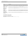
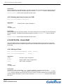
Description
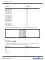
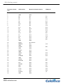
FPGA Pins
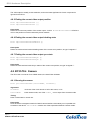
ADC0 data
K1, L4, L3, L2, L1, M4, M3, N4, N2, P4
ADC0 Trigger
N5
ADC0 DC Offset (PWM)
U18
ADC0 Standby
T18
ADC0 IRS
L6
ADC0 Clock
M5
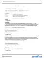
ADC1 data
U1, T1, T2, T3, R1, R2, R3, P1, P2, P3
ADC1 Trigger
M1
ADC1 DC Offset (PWM)
P16
ADC1 Standby
R16
ADC1 IRS
K4
ADC1 Clock
L5
NotShutdown - both ADCs
R17
3.10 RC10: Video Outputs
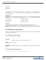
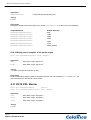
The RC10 has two video output capabilities: VGA and LCD. At present a LCD screen is not shipped with
the RC10, so the data included here for the LCD output is for information only.
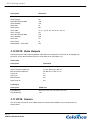
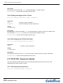
VGA output
Description
FPGA Pins
Red component data pins
D5, A4, B4, C4, A3, B3, A2
Green component data pins
C7, D7, B6, D6, A5, B5, C5
Blue component data pins
A9, B9, D9, F9, E9, E7, A7
HSync pin
P7
VSync pin
P6
DDC Data pin
P8
DDC Clock pin
R9
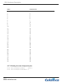
LCD output
Description
FPGA Pins
LCD data pins
H13, H14, J15, J14, F14, G14, H16, H15
LCD Enable pin
J18
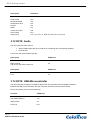
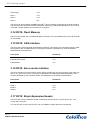
3.11 RC10: Camera
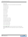
The RC10 has a connector for a CMOS camera, the OmniVision OV9650. The pin numbers are as
shown below:
Page 22
www.celoxica.com