1
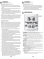
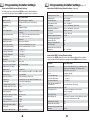
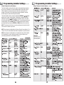
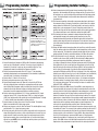
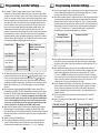
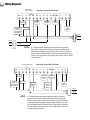
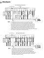
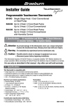
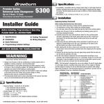
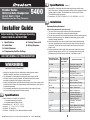
1 Specifications cont.
Premier Series
Universal Auto Changeover
Up to 3 Heat / 2 Cool
5400
Conventional and Heat Pump Thermostat
Installer Guide
Before Installing, Programming or Operating,
PLEASE READ ALL INSTRUCTIONS
1 Specifications
5 Testing Thermostat
2 Installation
6 Wiring Diagrams
3 Quick Reference
4 Programming Installer Settings
SEE USER MANUAL FOR TROUBLESHOOTING
WARNING
Important Safety Information
• Always turn off power to the air conditioning or heating system prior to
Installing, removing, cleaning or servicing thermostat.
• This thermostat is a dual power thermostat and either requires 24 Volt
AC Power or two (2) properly installed “AA” Alkaline batteries for normal
operation and control of the heating or cooling system.
• Properly installed batteries will allow the thermostat to retain clock settings in the
event of loss of AC Power due to power outage or rolling blackouts when used as
a hardwired thermostat.
• This thermostat should only be used as described in this manual. Any other
use is not recommended and will void the warranty.
1 Specifications
• Electrical Rating: 24 Volt AC (18-30 Volt AC)
1 amp maximum load per terminal
6 amp maximum load (all terminals)
• Control Range: 45º - 90º F (7º C - 32º C)
• Accuracy: +/- 1º F (+/- .5º C), +/- 3% RH
• AC Power: 18-30 Volt AC
• DC Power: 3.0 Volt DC (2 “AA” Alkaline batteries included)
©2008 Braeburn Systems LLC • Patents Pending • All Rights Reserved. Pub. No. 5400-100-007
• Compatibility: Compatible with low voltage single stage or multi-stage
Heat / Cool systems, including heat pumps with up to three stages of heating
and two stages of cooling. This thermostat can also be used on 250 to
750 millivolt heating only systems.
• Terminations: A/D, H, G, Rc, Rh, W2, B, O, Y1, Y2, W1/E/W3, C, L, S1, S2
2 Installation
Replacing Existing Thermostat
Most existing thermostats have three parts:
• The cover, which may snap or hinge over the existing thermostat.
• The electronics or body, which controls the existing system.
• The sub-base, where the wires attach through the wall to the existing system.
1. Always turn off power to the air conditioning and heating system prior to
removing existing thermostat.
2. Carefully remove the cover and electronics body from the old thermostat
sub-base. Depending on the brand, these parts may pull off or need to be
unscrewed. The old sub-base should remain wired and on the wall until
steps 4 and 5.
3. Label every old wire with the letter of the connection to which the wire is
attached. Example letters are R, M, Y, etc. Depending on the brand of the
old thermostat, your letters may be different. (continued on page 2)
Old Terminal from
Existing Thermostat
New Terminal for
New Thermostat
(Model 5400)
Terminal Description
A, DHM
A/D
External Air output or Fan
Speed Reduction Relay
H
G or F
H
G
Rc
R, V-VR or VR-R
W1, W2 or W-U
B
O or R
Y, Y1 or M
Y2
W1/E/W3
Rh
W2
B
O
Y1
Y2
W1/E/W3
C, X or B
C
L or X
S1
S2
L
S1
S2
Humidifier Output
Fan Control
24 Volt AC (Cooling for
Dual Transformer Systems)
24 Volt AC
Stage 2 Heating
Reversing Valve (Heating)
Reversing Valve (Cooling)
Stage 1 Compressor
Stage 2 Compressor
1st Stage Heating for
Conventional Systems or
Emergency Heating for 3
Stage Heat Pumps
24 Volt AC, Transformer
Common
System Malfunction Indicator
Optional Remote Sensor
Optional Remote Sensor
1
2 Installation cont.
2 Installation cont.
Replacing Existing Thermostat (continued)
Installing New Thermostat (continued)
4. After labeling the old wires, loosen each connection and remove them from
old sub-base. Secure the wires to prevent them from slipping into the opening
in the wall.
5. Remove the old sub-base from the wall, again being careful that the wires do
not slip into the opening in the wall.
6. Use the chart on page 1 to determine the new thermostat connections. As an
example, if the old thermostat had a G or F connection, it goes to G on the new
thermostat. It may be helpful to use the chart by circling (with a pencil or pen)
the letter of each wire removed from the old thermostat.
11. Flip the front thermostat cover up and open the battery compartment door.
12. Locate the positive [+] ends of the batteries and match them with the positive
[+] terminals located in the battery compartment. Install the two new “AA”
alkaline batteries (supplied). Close battery compartment door.
13. Restore system power and proceed to programming and system checkout.
3 Quick Reference
NOTE: This thermostat is designed for use on low voltage 24 volt AC single stage
or multi-stage systems, including heat pumps with up to three stages of heating
and two stages of cooling. Do not use this thermostat on systems with voltage
higher than 30 Volts AC. This thermostat requires a transformer common wire for
proper installation if used as a hardwired thermostat.
Model 5400 shown
with cover open
Installing New Thermostat
8
NOTE: When installing this thermostat in a new location, following a few simple
guidelines and the applicable building codes will give the best results. Install the
thermostat in a location that provides good airflow by avoiding areas behind
doors, near corners, air vents, direct sunlight or heat generating devices. The
wiring must conform to all building codes and ordinances as required by local
and national code authorities having jurisdiction for this installation.
1. Always turn off the power to the air conditioning and heating system prior
to installing this thermostat.
2. Locate the release latch on the bottom (not the back) of the thermostat.
Press the release latch in and separate the body from the sub-base of the
thermostat. Because this thermostat has 15 possible connection points, you
may need to apply moderate force to separate the parts.
3. Set the thermostat electronics and cover down on a clean surface. Place the
sub-base on the wall in the desired location.
4. Using the slotted mounting holes in the sub-base, mark the placement of the
mounting holes through the slots and onto the wall. Ensure the wires come out
of the wall into the center hole of the sub-base.
5. After verifying the drill will not damage items in the wall, use a 3/16 drill to
create the mounting holes. Gently tap the supplied plastic anchors into the
holes in the wall.
6. Place the thermostat sub-base against the wall in the desired location. Ensure
the thermostat is level, the wires are inserted in the opening, and the mounting
holes are aligned with the slots on the sub-base.
7. Fasten sub-base to wall using supplied screws into the plastic wall anchors.
8. Connect wires to the quick wiring terminal blocks. Use the wiring diagram
chart to ensure the old and new connections are correct.
9. To prevent electrical shorts and potential damage to the thermostat, make
sure all wire connections are secure and not touching each other.
10.Locate the thermostat body, and ensure the cover is still installed properly.
Using the mounting tabs on the top of the sub-base as a guide or hinge, close
up the thermostat case by pivoting the body and cover closed. The latch on the
bottom of the thermostat will click when the case is properly closed. Because
this thermostat has 15 possible connection points, you may need to apply
moderate force to close the case. (continued on page 3)
2
10
9
7
1
6
2
3
4
5
SYSTEM Button: Selects AUTO (Heat/Cool), COOL, OFF, HEAT or EMER.
PROG Button: Program setup mode; selects set point time, set point temperature and fan
setting for each program. Scrolls backwards between installer setup screens.
3 HOLD Button: Enables extended hold, clears extended hold or temporary override.
4 RETURN Button: Scrolls between installer setup screens, or returns unit to the normal
mode from program mode. Option setting mode for stage differential and residual cooling
Is entered when holding the RETURN button for 4 seconds when in the normal mode.
5 DAY/TIME Button: Selects hour, minute and day setting. Selects program day in program
setting mode.
6 FAN Button: Selects AUTO, ON, CIRC (recirculate) and PROG (program) modes.
7 RESET Button: Located on front of thermostat. See Page 5 for a list of all functions that
will return to their factory default settings after the RESET button is pressed.
8
Button: Turns on backlight for 10 seconds.
9
Button: Increases setting (time, temperature, etc.). Scrolls between option settings.
10
Button: Decreases setting (time, temperature, etc.). Scrolls between option settings.
4 + 2 RETURN and PROG Buttons: When pressed at the same time, returns unit to the
normal mode from Installer setup option mode. To enter installer mode, press and hold
both the RETURN and the arrow button for 3 seconds.
2 + 5 PROG and DAY/TIME Buttons: When pressed at the same time, displays the current
room humidity and humidification set points.
2 + 3 HOLD and PROG Buttons: When pressed at the same time, displays outdoor sensor if
installed and enabled.
CLEAR Button: Located on the back side of the circuit board; resets thermostat to all
factory default settings. See Page 4 and 5 for a complete listing.
1
2
3
4 Programming Installer Settings
Status After CLEAR–Factory Default Settings
At initial power up or after Installer CLEAR is pressed, the thermostat is
reset to factory defaults. Installer CLEAR is located on the circuit board.
4 Programming Installer Settings cont.
Status After CLEAR–Factory Default Settings (continued)
Function
Status After CLEAR
Auxiliary Balance Point
0 deg – No Lockout
Humidification
10%, disabled
80%, disabled
Function
Status After CLEAR
Operation mode
OFF, Auto Changeover enabled
Dehumidification
Temperature hold
Permanent and temporary hold cleared
Economizer Control
None – Disabled
Fan Switch
AUTO
UV Monitor
0 days – No Warning, Timer reset
Clock
12:00 pm, Monday
Humidifier Pad Monitor
0 days – No Warning, Timer reset
Room temperature
Display 70° F (21.0° C), to be renewed within
5 seconds
Heat Limit
90 deg – No Limit
Set point temperature
62° F (17.0° C) for Heat and Emergency Heat
83° F (28.0° C) for Cool
Cool Limit
45 deg – No Limit
Maximum Override Duration
4 hours
Zero Stage Differential for
Dehumidification
1.0º F
Maximum Humidification
Set Point Limit
ON
Dehumidification Fan Speed
Reduction
OFF – Disabled
Temperature scale
Fahrenheit
Operating program
DAY program, Monday
Low-battery warning
Off, to be renewed within 5 seconds
AC interrupted warning
Off, to be renewed within 5 seconds
1st stage differential
.5° F (0.2° C)
2nd stage differential
2° F (1.0° C)
3rd stage differential
2° F (1.0° C)
Programming
7 Day, 4 Event
Status After RESET–Factory Default Settings
When the User RESET button is pressed, the following options will reset to the
factory defaults. All other settings are saved when the RESET button is pressed.
Deadband
3° F
Residual Cooling Fan Delay
60 seconds
Short cycle protection timer
On, 5 minutes, Reset
Function
Status After RESET
Adaptive Recovery Mode
ON
Programming
Output relays
All turned off
Recirculating Fan
Timer reset, with 24 min OFF, 12 min ON, Lock OFF
Default setting depending on programming mode
setting (see User Manual). For manual mode:
Heat - 62° F, Cool - 83° F.
Extended Hold
Long (indefinite)
Clock
12:00 pm, Monday
Filter Check Monitor
0 days-No Warning, Timer reset
1st stage differential
.5° F (0.3° C)
Keypad Lock
Complete (level 2), unlocked, 555 universal code
2nd stage differential
2° F (1.0° C)
System type
Conventional, Single Stage
3rd stage differential
2° F (1.0° C)
1st Stage Heat Fan Control
Gas
2nd Stage Heat Fan Control
Electric
Filter, UV and Humidity Pad
Check Monitor
0 days-No Warning, Timer reset
Fossil Fuel Compressor Lock
Off
Auto Changeover
Enabled
Compressor Outage Protection
Temperature Sensor
12 / 24 Hour Clock
12 hour
Adjustment Limit from Set Point 0, OFF
Temperature Hold
Permanent and temporary hold cleared,
reset to Long Hold
Off, Timer reset
Short Cycle Timer
Reset
Internal
Recirculating Fan
Timer reset, 24 minute off cycle. With recirculating
lock set, fan state defaults to CIRC.
Adjustment Limit from Set Point 0, OFF
Humidification Setting
10%
AC Interrupt Warning Mode
OFF
Dehumidification Setting
80%
User Profile
Residential
Compressor Balance Point
0 deg – No Lockout
Maximum Temporary Override
Duration
4 hours
4
5
4 Programming Installer Settings cont.
Setting Thermostat Installer Options
4 Programming Installer Settings cont.
Setting Thermostat Installer Options (continued)
The Installer Options section allows the system and programming parameters
to be set up at installation. The Installer Options mode is menu driven. As the
different options are programmed you may eliminate specific options. For
example, if the system is set to single stage heat pump, Option 8, selecting
the AUX stage fan control will no longer be available.
The Installer Option mode is entered by holding the RETURN and or buttons
together for 3 seconds. Installer Option 1 (Residential or Commercial) will be
displayed. Pressing the or buttons will scroll between choices. To scroll to
the next installer option, press the RETURN button. To scroll backwards between
installer options, press the PROG button. The thermostat will return to normal
operating mode by pressing the RETURN and PROG buttons at the same time.
NOTE: The thermostat will return to normal operating mode automatically after
30 seconds if no buttons are pressed.
NOTE: Any changes to Installer Option 6 (System Type) will cause Options 7, 8, 9,
10 and 11 to reset to the default values that are dependent on system selection.
NOTE: Any changes to Installer Options 1 through 6 will cause all User Options
and Programming to reset to their default values if the User Options were
previously programmed. See User Manual, Section 2.
6
IMPORTANT:
At installation, Remote
Indoor Sensor must be
at room temperature.
7
4 Programming Installer Settings cont.
Setting Thermostat Installer Options (continued)
Available only in Business Mode
and if Dehumidification Fan Speed
Control is set to NO. Selects
Outside Air Intake Options of None
(disabled), Economizer Mode and
Time of Day Mode.
1. Selects Residential or Commercial (BUS) profile. Determines programming
events per day. If Residential is selected, 4 events per day are available. If
Commercial is selected, 2 events per day are available. Only the 7 day
programmable mode is available for the Commercial profile.
2. Selects the programming mode, either full 7 day or 5-2 day (weekdayweekend) programming or non-programmable. If the Commercial profile was
selected in step 1 this option is not available.
3. Selects either a 12 hour or 24 hour clock.
4. Selects preferred temperature scale of either ºF or ºC.
5. Selects Auto Changeover on or off. When off is selected, the AUTO icon
will not be displayed when selecting the system options with the system
switch. When Auto Changeover mode is enabled and selected, the system
automatically switches between heating and cooling when the room
temperature meets the programmed heating or cooling set points.
6. Selects single stage conventional (11C), 2 stage conventional (22C), single
stage heat pump (11HP), 2 stage heat pump (22HP), or 3 stage heat pump
(32HP). Any change made to the system type resets Installer Options 7 through
11 to their default values dependent on system selected.
7. Selects between 1st stage gas or electric heat Fan Control. This Installer
Option is not available with a heat pump system.
8. Selects aux-stage gas or electric heat Fan Control. This Installer Option is only
available with a 2 or 3 stage heat pump system.
9. For heat pump units with an electric auxiliary stage, both the first and second
stages of heating will run when a call for second stage heat is made. For heat
pump units with a fossil fuel auxiliary stage, the compressor stage(s) will be
locked out one minute after a second stage heat call, and the second stage
will only be used. NOTE: Can be overridden by auxiliary balance point. See item
25 on page 11 for details.
8
4 Programming Installer Settings cont.
10. Select between turning the AC power interrupt warning off or on. During a
power loss, the thermostat will display an outage warning. The system clock
will continue to run, and all settings will be maintained until the outage period
is over. This Installer Option is only available when thermostat is installed as
a hardwired unit.
11. This thermostat provides cold weather compressor protection by locking out
the compressor stage (1st stage) of heating for a period of time after a power
outage greater than 60 minutes. The lockout period is one hour less than the
outage time, up to a maximum of 12 hours. During that period of time, the
auxiliary heat stage will still be available to maintain the set point temperature.
The compressor lockout can be disabled by setting this option to OFF.
12. This thermostat includes an automatic compressor protection feature to
avoid potential damage to the cooling system from short cycling. This
thermostat automatically provides an adjustable delay after turning off the
cooling system output to protect the compressor. This protection is also present
in the heat mode of operation on single stage heat pump systems to protect
the compressor.
13. During the COOL mode of normal operation the fan will stay on for 60 seconds
after the cooling system has satisfied the set point temperature and has turned
off the compressor. This allows the system to provide higher efficiency during
cooling operation.The delay is selectable between 0, 30, 60 or 90 seconds.
14. The Recirculating Fan can be “locked on”, so that the only fan selections
available to the user are CIRC and ON. The Recirculating Fan Mode provides
more even temperature distribution and improves indoor air quality by
circulating air through the furnace filtration system more often. By locking the
Recirculating Fan on, the user will only have the option to run the fan all the
time (ON) or use the Recirculating Fan Feature (CIRC). If the Recirculating Fan
lock is set to off, the thermostat is put into the Recirculating Fan Mode by
pressing the FAN button until the CIRC icon is displayed. If no call for heating or
cooling occurs within the fan off cycle set in the User Options (see User Manual),
the fan will run for 24 minutes. When the fan lock is set to on, the highest
setting, 120 minutes, will run the fan least often – 9% minimum running time.
The lowest setting, 24 minutes (factory default), will run the fan most often –
33% minimum running time. The Recirculating Fan feature is available in the
COOL, OFF, HEAT, or EMER mode.
15. Enables or disables the ARM™ feature. During ARM™, room temperature is
recovered gradually by turning on the heating or cooling before the end of the
set back period. In a multi-stage configuration, room temperature is recovered
gradually by using only the first stage heating or cooling until the last 20
minutes, to minimize the use of the 2nd stage heating or cooling. The set point
temperature is changed to that of the upcoming comfort program temperature.
The start time of recovery is based on the difference between the current room
temperature and the upcoming comfort program set point temperature. The
recovery to the upcoming heating set point starts 10 minutes before the
upcoming set point time for each degree of temperature change required, up to
a maximum of 2 hours. The recovery to the upcoming cooling set point starts 15
minutes before the upcoming set point time for each degree of temperature
change required, up to a maximum of 3 hours. ARM™ does not operate when
the unit is in the temporary or permanent HOLD mode or if the program is
temporarily overridden or if emergency heat is selected for multi-stage heat
pumps. If the ARM™ feature is disabled the thermostat will recover the set point
temperature at the programmed set point time after the setback period ends.
9
4 Programming Installer Settings cont.
16. If a Braeburn® indoor or outdoor remote sensor is connected during
installation, the thermostat will automatically detect the type of sensor. When
an indoor sensor is detected, you may select between internal (sensI), external
(sensE), or averaging (sensA) of internal and external for temperature control.
When an outdoor sensor is automatically detected, the thermostat will remove
the choices for indoor sensing from the menu and enable outdoor measurement. The outdoor sensor may be used to determine if balance points have
been exceeded, for outdoor temperature dependent humidity control, and
outdoor temperature display. For proper auto-detection, you must use a
Braeburn brand external sensor. Should the external sensor become unwired,
the thermostat will retain the settings, but the balance points, temperature
dependent humidity control, and outdoor temperature display will be disabled
until the external sensor is repaired. Test the operation of the external sensor
by pressing the PROG and HOLD buttons at the same time.
Option Setting
Temperature
Control
Balance Points and
Humidity Set Limit Control,
Outdoor Display
sens I (Internal
Thermostat Sensor)
At Thermostat
N/A
sens R (Remote
Indoor Sensor)
At Remote Sensor
N/A
sens A (Internal
and Remote)
Average between
Internal and Remote
N/A
17. The keypad lockout feature has two levels of security. Level one locks all
buttons (including the reset) except for the , and backlight buttons. Level
2 locks the entire keypad except the backlight button. The and buttons
can be pressed together to enter the lock code but the buttons do not work
individually to adjust the temperature. The lock level is set during the Installer
Options and the lock code is set in the User Options. See the User Manual,
Section 2.
18. Selects between disabling humidification (NONE), manual control (DEP), or
independent control (IND). The DEP setting controls humidification only during
heating calls. The IND setting allows humidification output in the heat mode,
but does not require a heat call. Braeburn recommends that the IND setting
only be used with systems designed for low air temperature humidification
such as steam humidification. Always ensure the heat exchanger or other
system parts are NOT exposed to excess water from condensation or other
sources. When there is any doubt, use the NONE or DEP setting.
19. Only available if outdoor sensor is connected and humidification is enabled.
Select between turning the Automatic Humidity Set Point limit OFF or ON.
Selecting OFF lets you set the Automatic Humidity Set Point manually. Selecting
ON limits the automatic set point which reduces the chance of condensation
on windows.
20. Enables or disables Dehumidification.
21. Zero stage dehumidification differential selects the number of degrees the
system is allowed to over-cool in attempting to reduce humidity. Options
available when dehumidification is enabled are 1˚, 2˚, or 3˚ F. (continued)
10
4 Programming Installer Settings cont.
22. Feature accommodates either a normally open relay or a normally closed relay.
Selects between Dehumidification fan speed limiting off (NO), or on: D output
normally active (NA) and D output normally inactive (NI).
23. When Auto Changeover mode is enabled and selected, the system automatically
switches between heating and cooling when the room temperature meets the
normal criteria for either a heating or cooling call. There is a forced separation
(dead band) between the heating and cooling set points, so the systems do not
work against each other. This option selects Auto Changeover Dead Band of 2º,
3º, 4º or 5º F. The default is 3º F unless dehumidification is enabled. When
dehumidification is enabled, the deadbands are as follows:
Dehumidification
Zero Stage Differential
Allowable Dead Band
Dehumidification not Enabled
2, 3, 4 or 5˚ F
1˚ F
3, 4, or 5˚ F
2˚ F
4 or 5˚ F
3˚ F
5˚ F
24. Only available with multi-stage heat pump and outdoor sensor connected.
Locks out the use of the compressor heat stage for outside air temperatures
less than installer setting. Select from no lockout or a setting between 10º F to
50º F (-9º C to 10º C).
25. Only available with multi-stage heat pump and outdoor sensor connected.
Locks out the use of the auxiliary heat stage for outside air temperatures over
installer setting. Select from no lockout or a setting between 70º F to 40º F
(21º C to 4º C). NOTE: This balance point overrides the fossil fuel compressor
lockout. If the lockout is set to AG and the outdoor temperature is over the AUX
balance point, the compressor will remain on during a second stage call. The
unit will recover to the set point without the AUX stage.
26. Selects Outside Air Intake Options. Scroll between none (disabled), economizer
mode and time of day mode. Enables the operation of an outside air damper
system in either the economizer mode or time of day mode. Not available
unless the Dehumidification Fan Speed Limiting is set to NO. Available only in
commercial mode.
27. Selects the heating set point upper limit, scrolls between 90º F and 60º F
(32º C and 10º C).
28. Selects the cooling set point lower limit, scrolls between 45º F and 80º F
(7º C and 27º C).
Time Step / Override
Cooling Call
External Air Output (A)
Economizer Time of Disabled
Mode
Day Mode
Occupied
Unoccupied
Override
YES or NO
ON
ON
OFF
YES
ON
OFF
OFF
NO
OFF
OFF
OFF
YES or NO
ON
ON
OFF
11
5 Testing the Thermostat
WARNING!
Read BEFORE Testing
• Do not short (or jumper) across terminals on the gas valve or at the heating or
cooling system control board to test the thermostat installation. This could
damage the thermostat and void the warranty.
• Do not select the COOL mode of operation if the outside temperature is below
50º F (10º C). This could possibly damage the controlled cooling system and
may cause personal injury.
• This thermostat includes an automatic compressor protection feature to
avoid potential damage to the cooling system from short cycling. The default
is to provide a 5-minute delay after turning off the cooling or heating output to
protect the compressor. This default can be changed in Section 4, Option 12,
Programming Installer Options.
NOTE: Test your thermostat prior to programming any user settings. Pressing the
Installer CLEAR button will reset the thermostat to all factory default settings. See
Page 4 and 5 for a complete listing. See Page 5 for a list of all functions that will
return to their default settings after the RESET button is pressed.
1. Using the system button, scroll through settings on the left side of the display
to HEAT.
2. Press the button on the keypad until the set point temperature setting is
a minimum of 3 degrees higher than the current room temperature. The
heating system should start within several seconds. The fan may not turn
on immediately due to the heating system built-in fan delay.
3. Scroll through system settings to OFF. The heating system should stop within
several seconds.
4. Scroll through system settings to COOL.
5. If the compressor has previously been running, then you must wait 5 minutes,
or until the installer programmed delay set in Section 4, Option 12, for the
automatic compressor short cycle protection period to expire. You can also
press the RESET button to bypass this feature for initial testing purposes.
See Section 4, Page 5 for a list of all functions that will return to their factory
default settings after the RESET button is pressed.
6. Press the button on the keypad until the set point temperature is a minimum
of 3 degrees lower than the current room temperature.
7. The cooling system should start within several seconds. Scroll through system
settings to OFF. The cooling system should stop within 90 seconds (dependent
on the setting of the Residual Cooling Fan Feature).
8. Scroll the fan settings to ON, the system blower should start.
9. Scroll the fan settings to AUTO, the system blower should stop.
10. If thermostat is controlling auxiliary equipment, adjust thermostat setting to test
humidifier, economizer, etc. if applicable.
12
6 Wiring Diagrams
Remove Factory
Installed Jumper
H
G
Rh
Rc
W2
B
O
2nd Stage
Heat
Control
Humidifier
Y1
Y2 W1/E/W3
Compressor
Control
C
Heat
Control
Fan Control
Outside Air
Control or Fan
Speed Reduction
Relay (NOTE 3)
L
Transformer Common
(See Note 1)
A/D
Conventional Systems (Dual Transformer)
S1
S2
Remote
Sensor
(NOTE 2)
Neutral
120 VAC
24 VAC
Hot
Neutral
Heating
24 VAC
Hot
NOTES:
Cooling
1. Transformer Common connection not required for battery-only operation
of thermostat. 2. Remote Sensor Terminals can be either for Outdoor or Indoor
Remote Sensor depending on installer settings. 3. Terminal can be used either for
Outside Air Control or Dehumidification Fan Speed Reduction depending on installer
settings. 4. For millivolt or other 2 wire heating systems, connect wires from heating
control to R and W1.
Conventional Systems (Single Transformer)
Factory Installed Jumper
A/D
H
G
Rc
Rh
W2
Fan Control
O
Y1
Y2 W1/E/W3
1st Stage
Compressor
Control
Humidifier
Outside Air
Control or Fan
Speed Reduction
Relay (NOTE 4)
B
2nd Stage
Heat Control
(NOTE 2)
1st Stage
Heat Control
2nd Stage
Compressor
Control
(NOTE 2)
C
L
Transformer Common
(See Note 1)
120 VAC
S1
S2
Remote
Sensor
(NOTE 3)
Neutral
24 VAC
120 VAC
Hot
NOTES:
1. Transformer Common connection not required for battery-only operation
of thermostat. 2. Second Stage Control connections not used for single stage
heating or cooling systems. 3. Remote Sensor Terminals can be either for Outdoor
or Indoor Remote Sensor depending on installer settings. 4. Terminal can be used
either for Outside Air Control or Dehumidification Fan Speed Reduction depending
on installer settings. 5. For millivolt or other 2 wire heating systems, connect wires
from heating control to R and W1.
6 Wiring Diagrams
One and Two Stage Heat Pump Systems
Factory Installed Jumper
Outside Air
Control or Fan
Speed
Reduction Relay
(NOTE 7)
H
G
Rc
Rh
2nd Stage
Heat Control
(NOTE 2)
Humidifier
Fan Control
O
B
W2
Y1
Reversing Valve
(Active in
Cooling - See
NOTE 3)
2nd Stage
Compressor
Control
(NOTE 2)
Emergency
Heat Control
(See NOTE 4)
1st Stage
Compressor
Control
Reversing Valve
(Active in
Heating - See
NOTE 3)
S1
L
C
Y2 W1/E/W3
Transformer Common
(See NOTE 1)
A/D
(See NOTE 5)
S2
System
Malfunction
Indicator
(NOTE 8)
Remote
Sensor
(NOTE 6)
Neutral
24 VAC
120 VAC
Hot
1. Transformer Common connection not required for battery-only operation of thermostat.
2. Second Stage Control connections not used for single stage heating or cooling systems.
3. For units requiring reversing valve to be energized during heating, connect reversing valve to B
terminal. For units requiring reversing valve to be energized during cooling, connect reversing valve
to O terminal. 4. Required for units with 2 stage heat only. 5. For 2 stage heat units not having a
separate Emergency Heat Terminal, add installer supplied jumper. 6. Remote Sensor Terminals can
be either for Outdoor or Indoor Remote Sensor depending on installer settings. 7. Terminal can be
used either for Outside Air Control or Dehumidification Fan Speed Reduction depending on installer settings.
8. If L Terminal is used, 24VAC common (C terminal) must be connected.
Factory Installed Jumper
A/D
Outside Air
Control or Fan
Speed
Reduction Relay
(NOTE 4)
H
G
Humidifier
Fan Control
Rc
Rh
W2
Three Stage Heat Pump Systems
O
B
Y1
Reversing Valve
(Active in
Cooling - See
NOTE 2)
Reversing Valve
(Active in
Heating - See
NOTE 2)
Y2
W1/E/W3
2nd Stage
Compressor
Control
1st Stage
Compressor
Control
Aux Heat
Control
C
Transformer Common
(See NOTE 1)
NOTES:
L
S1
S2
System
Malfunction
Indicator
(NOTE 5)
Remote
Sensor
(NOTE 3)
Neutral
24 VAC
120 VAC
Hot
NOTES:
1. Transformer Common connection not required for battery-only operation of thermostat.
2. For units requiring reversing valve to be energized during heating, connect reversing valve
to B terminal. For units requiring reversing valve to be energized during cooling, connect
reversing valve to O terminal. 3. Remote Sensor Terminals can be either for Outdoor or Indoor
Remote Sensor depending on installer settings. 4. Terminal can be used either for Outside Air Control
or Dehumidification Fan Speed Reduction depending on installer settings. 5. If L Terminal is used,
24VAC common (C terminal) must be connected.
5
YEAR
LIMITED
WARRANTY
Store this
booklet for
future reference
For more information on energy
savings, go to www.energystar.gov
Braeburn Systems LLC, as an Energy Star partner
has determined that this product meets the Energy Star
Guidelines developed by the U.S. Environmental
Protection Agency & the U.S. Department of Energy for
maximum energy efficiency.
Braeburn Systems LLC warrants each new Braeburn thermostat against any defects that are
due to faulty material or workmanship for a period of five years after the original date of
purchase by a professional service technician. This warranty and our liability does not apply to
batteries, nor does it include damage to merchandise or the thermostat resulting from
accident, alteration, neglect, misuse, improper installation or any other failure to follow
Braeburn installation and operating instructions.
Braeburn Systems LLC agrees to repair or replace at its option any Braeburn thermostat
under warranty provided it is returned postage prepaid to our warranty facility in a padded
carton within the warranty period, with proof of the original date of purchase and a brief
description of the malfunction. This limited warranty does not include the cost of removal or
re-installation.
This warranty gives you specific legal rights and you may also have other rights that vary from
state to state or province to province. Answers to any questions regarding our limited warranty
may be obtained by writing our corporate offices.
WARRANTY FACILITY: Braeburn Systems LLC
Attn: Warranty Department
2215 Cornell Avenue
Montgomery, IL 60538
Braeburn Systems LLC
2215 Cornell Avenue • Montgomery, IL 60538
Technical Assistance: www.braeburnonline.com
Call us toll-free: 866-268-5599 (U.S. Only)
630-844-1968 (Outside the U.S.)
©2008 Braeburn Systems LLC • Patents Pending • All Rights Reserved.
Made in China • No. 5400-100-007