1
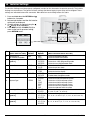
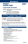
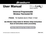
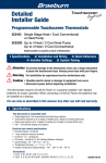
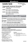
®
Installer Guide
TM
Universal Wireless Thermostat Kit
7500 Up to 3 Heat / 2 Cool Heat Pump
Up to 2 Heat / 2 Cool Conventional
with wireless Humidity Control*
* Wireless Humidity Control requires accessory model 7330.
1 Specifications 2 Installation and Wireless Setup 3 Quick Reference
4 Installer Settings 5 Wireless Remote Sensors 6 System Testing
Warning For installation by experienced service technicians only.
Caution • Possible electric shock or damage to equipment can occur.
• Disconnect power before beginning installation.
This thermostat requires 2 properly installed “AA” Alkaline batteries for proper
operation. When connecting optional 24 Volt AC power the batteries may be installed
as a backup.
For use only as described in this manual. Any other use will void warranty.
1 Specifications
KIT INCLUDES: Wireless thermostat, control module and return air plenum sensor.
This thermostat is compatible with:
•
•
•
•
Single stage heat / cool conventional and heat pump systems
Conventional systems up to 2 stages of heating and 2 stages of cooling
Heat pump systems up to 3 stages of heating and 2 stages of cooling
2 or 3 wire hydronic zone systems
Electrical and control specifications:
• Electrical Rating: 24 Volt AC
• 1 amp maximum load per terminal
• AC Power: 18 – 30 Volts AC
• DC Power: 3.0 Volt DC (2 “AA” Alkaline Batteries Included)
• Control Range: 45° – 90° F (7° – 32° C)
• Temperature Accuracy: +/- 1° F (+/- .5° C)
• Outdoor Temperature Display Range: -40° - 120° F (-40° - 49° C)
Terminations
Thermostat: R, C (optional 24 VAC power terminals)
Control Module: Rh, Rc, G, W1/E, W2/AUX, Y1, Y2, O/B/V3, L, C, P1, P2, S1, S2
7500-100-02
2 Installation and Wireless Setup
1 Install and Wire the Control Module
Warning Disconnect power before
beginning installation.
Control Module Location
Mounting
Hole
Install the control module on a wall near HVAC equipment
or on the HVAC equipment.
• Remove the cover of the control module.
• Mount the control module using the two mounting holes
and the appropriate type of screws for the application.
Connect
Button
Rc/Rh Terminal
Jumper (J1)
Install Return Air Sensor (required)
The Return Air Sensor maintains default temperature
control if wireless communication is lost.
• Install the Return Air Sensor at least 12 inches upstream
of any humidification or ventilation equipment.
• Connect the Return Air Sensor to the P1 and P2
terminals on the control module.
•For hydronic applications, mount sensor in an area that
maintains living space temperature. Do not mount
on the supply pipes.
Mounting
Hole
Wiring
Punchout
Wiring Terminations for Control Module
Terminal
Conventional Systems
Heat Pump Systems
Rh
24 Volt AC Heating Transformer
24 Volt AC Transformer
Rc
24 Volt AC Cooling Transformer
Not Used
G
System Fan Relay
System Fan Relay
W1/E
(W1) 1st Stage Heat Relay
(E) Emergency Heat Relay
W2/AUX
(W2) 2nd Stage Heat Relay
(AUX) Auxiliary Heat Relay
O/B/V3
(V3) Zone Valve Power Close
(Hydronic Systems Only)
(O) Cool Active Reversing Valve
(B) Heat Active Reversing Valve
Y1
1st Stage Cooling Relay
1st Stage Compressor Relay
Y2
2nd Stage Cooling Relay
2nd Stage Compressor Relay
L
Not Used
System Fault Indicator
C
24 Volt AC Transformer Common
24 Volt AC Transformer Common
S1
S2
Optional Wired Remote Sensor
(Indoor or Outdoor)
Optional Wired Remote Sensor
(Indoor or Outdoor)
P1
P2
Required Return Air Plenum
Sensor (must be installed)
Required Return Air Plenum
Sensor (must be installed)
Installer Guide
2
Wiring
Punchout
Conventional Systems
Typical Wiring Configurations
NOTE: The “System Type” option will be configured in Thermostat Installer Settings (section 4).
Heat Only
Hydronic Heat Only
Set System Type to 11CONV
Set System Type to 1HD
Rh
W1
G
C
24 Volt AC Power (heating transformer) [note 1]
Heat Relay
Fan Relay [note 3]
24 Volt AC Transformer Common
1 HEAT / 1 COOL Single or Dual Transformer
Set System Type to 11CONV
Rh
Rc
W1
Y1
G
C
24 Volt AC Power (heating transformer) [note 1]
24 Volt AC Power (cooling transformer) [note 1]
Heat Relay
Compressor Relay
Fan Relay
24 Volt AC Transformer Common [note 2]
2 HEAT / 2 COOL Single or Dual transformer
Set System Type to 22CONV
Rh
Rc
W1
W2
Y1
Y2
G
C
Rh
W1
V3
G
C
24 Volt AC Power (heating transformer) [note 1]
Zone Valve Power Open
Zone Valve Power Close
Fan Relay [note 3]
24 Volt AC Transformer Common
Hydronic Heat / 1 Cool
Set System Type to 11HD
Rh
Rc
W1
V3
Y1
G
C
24 Volt AC Power (heating transformer) [note 1]
24 Volt AC Power (cooling transformer) [note 1]
Zone Valve Power Open
Zone Valve Power Close
Compressor Relay
Fan Relay
24 Volt AC Transformer Common [note 2]
NOTES - Conventional Systems
[1]Open (J1) jumper for dual transformer installations.
[2]In dual transformer systems, transformer
common must come from cooling transformer.
[3]If needed for system.
Provide disconnect and overload protection as required.
24 Volt AC Power (heating transformer) [note 1]
24 Volt AC Power (cooling transformer) [note 1]
Heat Relay Stage 1
Heat Relay Stage 2
Compressor Relay Stage 1
Compressor Relay Stage 2 [note 3]
Fan Relay
24 Volt AC Transformer Common [note 2]
Additional Wiring Options
S1
S2
Indoor or Outdoor Remote Sensor [note 1]
NOTES - Additional Wiring Options
[1]These terminals can be used to connect a
Braeburn® wired indoor or outdoor remote sensor.
Indoor remote sensor must be configured in Thermostat Installer Settings (section 4).
3
Installer Guide
Heat Pump Systems
Typical Wiring Configurations
NOTE: The “System Type” option will be configured in Thermostat Installer Settings (section 4).
1 HEAT / 1 COOL - No Auxiliary Heat
3 HEAT / 2 COOL – Including Auxiliary Heat
Set System Type to 11HP
Set System Type to 32HP
Rh 24 Volt AC Power
O/B Changeover Valve [note 1]
Y1 Compressor Relay
G Fan Relay
C 24 Volt AC Transformer Common
Rh
24 Volt AC Power
O/B Changeover Valve [note 1]
Y1
Compressor 1 Relay (1st stage heating/cooling)
Y2
Compressor 2 Relay (2nd stage heating/cooling)
2 HEAT / 2 COOL - No Auxiliary Heat
Set System Type to 32HP
Rh 24 Volt AC Power
O/B Changeover Valve [note 1]
Y1 Compressor 1 Relay (1st stage heating/cooling)
Fan Relay
C
24 Volt AC Transformer Common
L
Optional System Fault Monitor [note 3]
2 HEAT / 1 COOL - Including Auxiliary Heat
Set System Type to 22HP
Rh
Auxiliary Heat Relay (3rd stage heating) [note 2]
E
Emergency Heat [note 2]
G
Fan Relay
C
24 Volt AC Transformer Common
L
Optional System Fault Monitor [note 3]
NOTES - Heat Pump Systems
Y2 Compressor 2 Relay (2nd stage heating/cooling)
G
AUX
[1] O (cool active) or B (heat active) is selected in
the Thermostat Installer Settings menu (section 4).
[2] Install a field supplied jumper between the
AUX and E terminals if there is no separate
emergency heat relay installed.
[3] If the L terminal is used, the 24 Volt AC common must be connected (C terminal).
Provide disconnect and overload protection as required.
24 Volt AC Power
O/B Changeover Valve [note 1]
Y1
Compressor Relay (1st stage heating/cooling)
AUX Auxiliary Heat Relay (2nd stage heating) [note 2]
E
Emergency Heat Relay [note 2]
G
Fan Relay
C
24 Volt AC Transformer Common
L
Optional System Fault Monitor [note 3]
Additional Wiring Options
S1
S2
NOTES - Additional Wiring Options
Indoor or Outdoor Remote Sensor [note 1]
Installer Guide
[1]These terminals can be used to connect a
Braeburn® wired indoor or outdoor remote sensor.
Indoor remote sensor must be configured in
Thermostat Installer Settings (section 4).
4
2 Install the Thermostat
NOTE: Test location by pairing your thermostat before mounting (see page 7).
Thermostat Location
Install the thermostat approximately 5 feet (1.5m) above the floor in an area that has a good amount of air
circulation and maintains an average room temperature.
Avoid installation in locations where the thermostat can be affected by drafts, dead air spots, hot or cold air
ducts, sunlight, appliances, concealed pipes, chimneys and outside walls.
3
Install the Sub-Base:
• Remove the sub-base from the body of the thermostat.
• Mount the sub-base as shown below:
Drill 3/16” pilot holes in your
desired location. Use supplied
anchors for drywall or plaster.
UP
UP
5
Installer Guide
4
Provide Power to Thermostat
R
+
C
+
24VAC Power (optional)
Battery Power
• For optional 24 Volt AC power, you must connect R and C terminal to the thermostat sub-base.
• For battery power, insert the 2 supplied “AA” type alkaline batteries into the battery compartment located in the rear housing of the thermostat. Make sure to position the Positive (+) and Negative (-) sides of the
batteries correctly with the +/- symbols in the battery compartment.
5
Attach Thermostat to Sub-Base
UP
UP
INSTRUCTIONS
DAY/TIME
1) Line up the thermostat body with the sub-base.
2) Carefully push the thermostat body against the
sub-base until it snaps in place.
3) Insert Quick Reference Card into slot
on top of thermostat.
NOTE: This thermostat ships configured as a 1H/1C conventional
thermostat. Confirm installer settings. See page 11.
Installer Guide
6
6
Pairing the Thermostat with Control Module
Pairing the Thermostat and Control Module
1. On the thermostat, press and hold down the HOLD and
RETURN buttons for 3 seconds.
2. The word CMOD (control module) will appear in the
display and the symbol will flash (see Figure 1). 3. On the powered control module, press and hold the
CONNECT button for 3 seconds (see Figure 2).
4.The control module will enter pairing mode for 60
seconds. During this time the blue COMM indicator on
the control module will flash o. nce every 2 seconds.
5.Once successfully paired, the symbol will stop
flashing and the blue COMM indicator on the control
module will turn on.
6. Press RETURN on the thermostat at any time to exit.
DAY/TIME
Figure 1
NOTE: In step 2, if the control module has already been
paired, the
symbol will not be flashing.
Replacing a Thermostat
If you are replacing a thermostat that is paired with an existing
control module, you will need to clear the control module and
pair it again with the newly installed thermostat.
1.Install the new thermostat. 2.On the control module, press and hold the CONNECT button
for 10 seconds until the red COMM indicator turns on.
3. Release the CONNECT button and the blue and red LED will
each flash once to indicate the control module was
successfully cleared.
4.Pair the new thermostat with the control module.
Connect
Button
PWR
COMM
Figure 2
Replacing a Control Module
If you are replacing a control module that is paired with an existing thermostat, you will need to clear the
thermostat’s control module settings before pairing the new wireless control module.
1.Install the new control module. 2.Thermostat control module settings are cleared by adjusting Installer Setting #29 to CLR2. This setting clears the connection between the thermostat and control module (see section 4).
NOTE: Be careful not to select CLR3 unless you want to clear all the thermostat settings.
3. Pair your new control module with the thermostat. See “Pairing the Thermostat with Control Module”.
Communication Loss
If communication between the thermostat and control module is lost, the red COMM indicator on the control
module will begin to flash once every 10 seconds. The control module will attempt to reconnect to the thermostat
several times automatically.
NOTE: To attempt to reconnect manually, press and hold the CONNECT button for 3 seconds.
The thermostat display will also indicate that communication has been lost by flashing COMM LOSS CMOD. During communication loss the return air sensor is used to maintain the factory default heating and cooling
temperatures.
7
Installer Guide
1
2
3
4
5
Control Module LED Indicators
1
PWR:
24 VAC Power Indicator
HEAT ON Indicator
3
COOL: COOL ON Indicator
4
FAN: FAN ON Indicator
5
COMM: Communication Indicator
2
HEAT:
Communication Indicator (COMM)
•Solid blue:
•Rapid blue flash:
•1 blue flash every 2 seconds:
•Flashing, then solid blue:
•1 red flash every 10 seconds:
Installer Guide
Normal Operation
Sending Data to Thermostat
Control Module in Pairing Mode
Successfully Paired
Lost Communication
8
3 Quick Reference
8
9
10
1
11
12
13
14
15
2
16
3
BACK
NEXT
4
5
HUMID
6
7
Thermostat Display
1
Room
Temperature....................... .Displays the current room temperature
2
Set Temperature........................... .Displays the current set point temperature
3
Outdoor Temperature Indicator.... .Displays along with the outdoor temperature reading**
4
BACK Indicator*............................ .BACK button is active
5
NEXT Indicator*............................ .NEXT button is active
6
Humidity Indicator ...................... .Indicates when there is a call for humidification or dehumidification
7
Service Indicators . ..................... .Displays various service/maintenance information
8
Fan Indicator................................. .Indicates when the system fan is running
9
Wireless Indicator......................... .Indicates a wireless connection (flashes when connection has been lost)
10
Low Battery Indicator................... .Indicates when the batteries need to be replaced
11
Hold Mode Indicator .................... .Indicates if the thermostat is in HOLD mode
12
Lock Mode Indicator . .................. .Indicates if the thermostat is locked
13
System Status Indicator .............. .Displays information about the status of the system
14
Day of the Week............................ .Displays the current day of the week
15
Program Event Indicator.............. .Displays the program event
16
Time of Day .................................. .Displays the current time of day
* BACK and NEXT are secondary functions of the PROG and HOLD buttons. When in programming or configuration modes, BACK and NEXT appear in the display screen indicating that the PROG and
HOLD buttons now function as BACK and NEXT.
** Also see #24 on page 10.
9
Installer Guide
22
INSTRUCTIONS
23
15
BACK
NEXT
18
19
DAY/TIME
16
17
20
21
24
25
Thermostat
15
Reset Button ................................ .Resets current time, program and user settings
16
SYSTEM Button............................. .Selects the system you want to control
17
DAY/TIME Button........................... .Sets the current time and day of the week
PROG Button................................. .Selects programming mode or press for 3 seconds to select SpeedSet®
BACK Button*................................ .Secondary function of the PROG button - moves back a setting
HOLD Button.................................. .Enters/Exits the HOLD mode (program bypass)
19
NEXT Button*................................ .Secondary function of the HOLD button - moves to next setting
20
RETURN Button............................. .Returns to normal mode from program or setting modes
21
FAN Button.................................... .Selects the system fan mode
22
Quick Reference Instructions....... .Stored in slot located at top of thermostat
23
SpeedBar® .................................... .Increases or decreases settings (time, temperature, etc.)
24
Outdoor Temperature.................... .If a Braeburn® outdoor sensor was connected you can view the outdoor . temperature by pressing the PROG and HOLD buttons at the same time.
25
Humidity Setpoint......................... .If a Braeburn wireless humidity sensor is connected you can view the
current humidity or make adjustments to the humidity setpoint by
pressing the DAY/TIME and RETURN buttons at the same time.
Battery Compartment......................... .Located in the back of thermostat
18
* BACK and NEXT are secondary functions of the PROG and HOLD buttons. When in programming or configuration modes, BACK and NEXT appear in the display, indicating that the PROG and HOLD buttons now function as BACK and NEXT.
Installer Guide
10
4 Installer Settings
The Installer Settings must be properly configured in order for this thermostat to operate correctly. The Installer
INSTRUCTIONS
Settings are menu driven.
The portion of these settings that do not apply to your setup will be skipped. These
settings are indicated below with comments. More detail on each setting follows this table.
1.
2.
3.
4.
Press and hold down the RETURN and buttons for 3 seconds.
Release both buttons and the first installer
setting will be displayed.
Change settings as required using the or portion of the SpeedBar®.
Press NEXT (HOLD) or BACK (PROG) to
move to the next or previous setting,
press RETURN to exit.
BACK
INSTRUCTIONS
NEXT
DAY/TIME
DAY/TIME
No. Installer Setting
Factory (Notes follow this table) Default
Setting
Options
Comments
1 Residential or
RES
or Commercial Profile
2 Programming Mode
7 PROG
[note 1]
3 Clock Format
12 HR
4 Temperature Scale
F DEG
5 Auto Changeover
oF AUTO
6 System Type
11CONV
7 1st Stage Differential
0.5 DIF1
8 2nd Stage Differential
2.0 DIF2
[note 2]
9 3rd Stage Differential
2.0 DIF3
[note 2]
RES
COMM
7 PROG
52 PROG
NO PROG
12 HR
24 HR
F DEG
C DEG
oF AUTO
ON AUTO
11CONV
22CONV
11HP
22HP
32HP
1HD
11HD
0.5, 1.0 or 2.0 DIF1
1.0, 2.0, 3.0, 4.0, 5.0 or 6.0 DIF2
1.0, 2.0, 3.0, 4.0, 5.0 or 6.0 DIF3
(More information follows this table)
Select for Residential profile
Select for Commercial profile
Select for 7 day programming mode
Select for 5-2 day programming mode
Select for non-programmable mode
Select for 12 hour clock
Select for 24 hour clock
Select for Fahrenheit display
Select for Celsius display
Disables Auto Changeover mode
Enables Auto Changeover mode
Select for 1H/1C Conventional system
Select for 2H/2C Conventional system
Select for 1H/1C Heat Pump system
Select for 2H/2C Heat Pump system
Select for 3H/2C Heat Pump system
Select for Heat Only Hydronic system
Select for Hydronic Heat/1C system
Select a 1st stage temperature differential of .5°,
1° or 2° F (.25°, .5° or 2° C)
Select a 2nd stage temperature differential of 1°,
2°, 3°, 4°, 5° or 6° F (.5°, 1°, 1.5°, 2°, 2.5° or 3° C)
Select a 3rd stage temperature differential of 1°, 2°,
3°, 4°, 5° or 6° F (.5°, 1°, 1.5°, 2°, 2.5° or 3°C)
11
Installer Guide
No. Installer Setting
Factory Setting
(Notes follow this table) DefaultOptions
10 1st Stage Fan Control
HG FAN 1
[note 3]
11 Emergency Heat]
HE EMER
Fan Control [note 4]
12 Reversing Valve
REVO
(O/B Terminal) [note 5]
13 Fossil Fuel
AE AUX
Backup Heat [note 4]
14 Compressor Power Outage oF CPOP
Protection [notes 4, 6]
AC oF MONR
15 AC Power Interrupt
Warning [note 6]
16 Compressor Short
5 CSCP
Cycle Protection [note 7]
17 Residual Cooling
60 FAN
Fan Delay [note 7]
18 Adaptive Recovery
oF REC
Mode (ARM™) [note 8]
19 Indoor Remote Sensor
I SENS
Control* [note 9]
20 Lockout Security Level
2 LOCK
21 Auto Changeover
3 BAND
Dead Band [note 10] 22 Compressor Balance
NO BALC
Point [notes 4, 11]
23 Auxiliary Heat Balance
NO BALA
Point [notes 4, 11]
Comments
(More information follows this table)
HG FAN 1
Select for 1st stage Gas heating
HE FAN 1
Select for 1st stage Electric heating
HE EMER
Select for Electric Emergency Heat
HG EMER
Select for Gas Emergency Heat
REVO
Select for cool active Reversing Valve (O terminal)
REVB
Select for heat active Reversing Valve (B terminal)
AE AUX
Select for Electric Auxiliary heat (with compressor)
AG AUX
Select for Gas Auxiliary heat (without compressor)
oF CPOP
Disables Power Outage Lockout Delay
on CPOP
Enables Power Outage Lockout Delay
AC oF MONR Disables AC Power Interrupt Warning
AC on MONR Enables AC Power Interrupt Warning
5, 4, 3, 2 or Select a compressor short cycle protection delay of 5, 0 CSCP 4, 3, 2 or 0 minutes
90, 60, 30 Select a Residual Cooling Fan Delay of 90, 60,
or 0 FAN 30 or 0 seconds.
oF REC
Disables Adaptive (early) Recovery mode
on REC
Enables Adaptive (early) Recovery mode
I SENS
Temperature is sensed from thermostat only.
E SENS
Temperature is sensed from remote sensor only.
A SENS
Temperature is combined with the thermostat and the remote sensor.
2 LOCK
If locked – Complete lockout is enabled
1 LOCK
If locked – Partial lockout is enabled (SpeedBar® is still functional)
2, 3, 4 or 5 Select a Dead Band of 2°, 3°, 4° or 5˚ F BAND (1°, 2° or 3° C) for Auto Changeover mode.
NO BALC
Disables Balance Points
0-50 BALC Select a Compressor Balance Point of 0°- 50°F
NO BALA
Disables Balance Points
70-40 BALA Select a Auxiliary Heat Balance Point of 70°- 40° F
24 Heat Set Point Upper Limit 90LIM
90-60 LIM
Select a Heat Set Point Upper Limit of 90°-45° F
25 Cool Set Point Lower Limit 45LIM
[note 7]
26 Humidification
OFF
[note 12]
27 Auto Humidity Set
AUTO
Point Limit [notes 11, 12] 28 Dehumidification
OFF
[note 12]
29 Installer Clear
CLR0
45-80 LIM
Select a Cool Set Point Lower Limit of 45°-90° F
OFF
DEP
IND
AUTO
MAN
OFF
NI
NA
CLR0
CLR1
CLR2
CLR3
Disables Humidification
Enables Dependant Humidification
Enables Independent Humidification
Enables automatic humidity control based on
outdoor temperature.
Enables manual humidity control from thermostat.
Disables Dehumidification
Normally inactive (open) relay
Normally active (closed) relay
Clear Off - No changes made to settings
Clears connection with wireless remote sensors
Clears connection with control module
Clears all thermostat settings (factory defaults)
Options (shaded) 26 - 28 only appear if optional wireless humidity sensor is installed. *When a Braeburn® outdoor sensor is
connected, the thermostat automatically recognizes it. Press PROG and HOLD at the same time to display outdoor temperature.
NOTE: Additional options such as Service Monitors, setting the lock code, etc. are located in the User Settings –
See User Manual for information on setting these options.
Installer Guide
12
NOTES - Installer Settings
1 Only available if Residential profile was selected in option 1.
2 Only available if a 2 or 3 stage system type was selected in option 6.
3 Only available if a Conventional system was selected in option 6.
4 Only available if a 2 or 3 stage Heat Pump system was selected in option 6.
5 Only available if a Heat Pump system was selected in option 6.
6 Only available if thermostat is 24 VAC powered (R and C terminals).
7 Not available if a heat only hydronic system is selected in option 6.
8 Only available if a programmable profile was selected in option 2.
9 Only available if a Braeburn® indoor remote sensor was connected.
10 Only available if auto changeover was enabled in option 5.
11 Only available if a Braeburn outdoor sensor was connected.
12 Only available if a Braeburn wireless humidity sensor was connected.
Detailed Explanation of Installer Settings (also see NOTES above):
1 Profile – Selects a residential (RES) or commercial (COMM) profile. If residential is selected, 4 programming events per day are available. If commercial is selected, 2 event, 7 day programming is available.
2 Programming Mode [note 1] – Selects the programming mode, either full 7 day or 5-2 day (weekday/
weekend) programming or non-programmable. 3 Clock Type – Selects either a 12 hour or 24 hour clock.
4 Temperature Scale – Selects a temperature scale of either °F or °C.
5
Auto Changeover – Selects auto changeover on or off. When auto changeover mode is enabled and selected, the system automatically switches between heating and cooling modes. There is a 5 minute delay when switching from heating to cooling or cooling to heating in auto changeover mode.
NOTE: Also see “Auto Changeover Dead Band” in option 21.
6 System Type – Selects the system type for your installation. NOTE: Changes made to this option will reset options 7 through 15 back to their default values dependant on the system type.
7 1st Stage Differential – Selects a 1st stage temperature differential.
8 2nd Stage Differential [note 2] – Selects a 2nd stage temperature differential.
9 3rd Stage Differential [note 2] – Selects a 3rd stage temperature differential.
10 1st Stage Fan Control [note 3] – Selects a 1st stage fan control of either gas or electric heat.
11 Emergency Heat Fan Control [note 4] – Selects emergency heat fan control of either gas or electric heat.
12 Reversing Valve [note 5] – Selects the output state of the O/B terminal. Select O for this terminal to be active in the cool mode or select B for this terminal to be active in the heat mode.
13
Auxiliary Fossil Fuel Heat Pump Control [note 4] – When set to electric (AE AUX), both the compressor (1st stage) and auxiliary stage(s) will run when a call for auxiliary heat is made. When set to gas (AG AUX), the compressor stage(s) will be locked out one minute after a call for auxiliary heat. NOTE: This option can be overridden if setting an auxiliary heat balance point in Option 23.
14 Compressor Power Outage Protection [notes 4, 6] – Selects power outage protection on or off. When enabled, this thermostat will provide cold weather compressor protection by locking out the compressor stage(s) of heating for a period of time after a power outage greater than 60 minutes.
13
Installer Guide
15 AC Power Interrupt Warning [note 6] – When enabled, the thermostat will display an outage warning when AC power to the thermostat is lost.
16 Short Cycle Protection [note 7] – Selects the number of minutes the cooling compressor will be locked out after turning off. This short cycle protection is also active in the heat mode if a heat pump system was selected in Option 6.
17 Residual Cooling Fan Delay [note 7] – Selects a delay for the system fan after the cooling compressor
has turned off. This delay will help remove the remaining cool air out of the ductwork providing additional efficiency.
18 Adaptive Recovery Mode (early recovery) [note 8] – Enables or disables the ARMTM (adaptive recovery mode) feature. During ARM, room temperature is recovered by turning on the heating or cooling before the end of the set back period. The set point temperature is changed to that of the upcoming program temperature.
19
Indoor Remote Sensor Control [note 9] – If a Braeburn® indoor remote sensor is connected (wired) or paired (wireless) during installation, the thermostat will automatically detect the sensor. When an indoor sensor is detected, you may select between thermostat only (I SENS), remote sensor only (E SENS) or
combining the thermostat and the remote sensor(s) (A SENS).
NOTE: This option does not apply to the Braeburn outdoor sensor. When an outdoor sensor is connected (wired) or paired (wireless), the thermostat automatically recognizes it and no further configuration
is necessary.
20
Lockout Security Level – Selects the level of keypad lockout when the thermostat is locked. Level 2 locks the entire thermostat (including the front reset button). Level 1 locks everything except the SpeedBar®
allowing for up and down temperature adjustment. NOTE: The lock code is set in the User Settings mode (see User Manual).
21
Auto Changeover Dead Band [note 10] – When auto changeover mode is enabled in option 5 and
selected, the system automatically switches between heating and cooling when the room temperature meets the normal criteria for either a heating or cooling call. There is a forced separation (dead band) between the heating and cooling set points so that the systems do not work against each other. This
option selects the amount of this dead band in degrees with the default being 3° F.
22 Compressor Balance Point [notes 4, 11] – Locks out the use of the compressor heat stage when the outside air temperature is less than the selected setting of 0° F to 50° F.
23
Auxiliary Heat Balance Point [notes 4, 11] – Locks out the use of the auxiliary heat stage when the outside air temperature exceeds the selected setting of 70° F to 40° F. NOTE: This balance point over
rides the fossil fuel compressor lockout in option 13. If this option is set to gas and the outdoor temperature is over the auxiliary balance point, the compressor will remain on during a call for auxiliary heat.
24 Heat Set Point Upper Limit – Selects the heating set point upper adjustment limit.
25 Cool Set Point Lower Limit [note 7] – Selects the cooling set point lower adjustment limit.
Installer Guide
14
26
Humidification Mode [note 12] – For use with an external humidifier. Selects between disabling
humidification (OFF), dependent control (DEP) or independent control (IND). The DEP setting controls
humidification only during a call for heating. The IND setting allows humidification output in the heat mode, but does not require a call for heating. NOTE: It is recommended that the IND setting only be used with systems designed for low air temperature humidification such as steam humidification. Always ensure the heat exchanger or other system parts are not exposed to excess water from condensation or other sources. When there is any doubt, use the OFF or DEP setting.
27
Auto Humidity Set Point Limit [notes 11, 12] – Select between turning the automatic
humidity set point limit to auto (AUTO) or manual (MAN). When AUTO is selected, humidity control is provided automatically based on the outdoor temperature. Selecting MAN allows you to manually control the level
of humidity.
28 Dehumidification [note 12] – For use with an external dehumidifier. Select between dehumidification disabled (OFF), a normally inactive (NI) or normally active (NA) relay, depending on the requirements of your external dehumidification equipment.
29
Installer Clear – Clears settings based on your selection. CLRO makes no changes, CLR1 clears all
wireless remote sensor connections, CLR2 clears the connection to the control module and CLR3 clears ALL thermostat settings.
WARNING: If you press NEXT or RETURN after selecting CLR1, CLR2 or CLR3 the clear will take place and the appropriate settings will be returned to factory defaults. If you do not wish to make any changes, use the SpeedBar® to select CLRO.
15
Installer Guide
5 Wireless Remote Sensors
NOTE: See the wireless remote sensor manual for complete installation and use instructions.
Compatible Wireless Remote Sensors
Wireless Remote Indoor Sensor(s) – 4 sensors maximum
Wireless Remote Outdoor Sensor – 1 sensor maximum
Wireless Remote Humidity Sensor – 1 sensor maximum
NOTE: No more than 4 wireless remote sensors can be connected.
Pairing Wireless Remote Sensors
1 Press and hold the HOLD and RETURN buttons for 3 seconds.
2 Press NEXT until the word SENS appears in the display and the symbol flashes.
3 After the remote sensor is powered, press and hold the CONNECT button on the sensor for 3 seconds
and release.
4 The remote sensor will enter pairing mode for 60 seconds. During this time the blue indicator on the wireless remote sensor will flash once every 2 seconds.
5 When paired, the thermostat display will change and indicate which remote sensor has been paired (see
Table 1). The symbol will stop flashing and the blue indicator on the remote sensor will turn on for
60 seconds.
6 To pair another wireless remote sensor, press NEXT and repeat steps 3 - 5.
7 Press RETURN at any time to exit.
NOTE: Sensors that have already been paired will appear in the thermostat display first, with a solid
IDS1, IDS2, IDS3 or IDS4
HMS ODS symbol.
Remote Indoor Sensor 1-4
Remote Humidity Sensor
Remote Outdoor Sensor
Using Wired Remote Sensors
Table 1
• One wired indoor or wired outdoor remote sensor can also be connected to the thermostats S1 and S2
terminals on the control module using 2-wire thermostat cable. • You cannot mix wired and wireless remote sensors of the same type (i.e. mixing an indoor wireless remote
sensor and an indoor wired remote sensor).
Replacing a Thermostat
If you are replacing a thermostat that is paired with an existing wireless sensor, you will need to clear the remote
sensor and pair it again with the newly installed thermostat.
1 Install the new thermostat. 2 On the wireless remote sensor you want to clear, press and hold the CONNECT button for 10 seconds until the red indicator turns on.
3 Release the CONNECT button and the blue and red indicator will each flash once to indicate the sensor was
successfully cleared.
4 Pair the remote sensor again.
Replacing a Sensor
If you are replacing a wireless remote sensor that is paired with an existing thermostat, you will need to clear the
thermostat’s remote sensor connection before pairing the new wireless remote sensor.
1 Install the new wireless remote sensor.
2 Thermostat remote sensor settings are cleared by adjusting Installer Setting 29 to CLR1 (see section 4). This setting clears all the remote sensors paired with the thermostat.
NOTE: Be careful not to select CLR3 unless you want to clear all the thermostat settings.
3 Once the remote sensor settings are cleared you will need to pair your new wireless remote sensor. You will also need to pair any other existing wireless remote sensors that were previously connected.
Installer Guide
16
Wireless Remote Sensor Communication Loss
If communication between the remote sensor and thermostat is lost, the red indicator on the remote sensor
will begin to flash once every 10 seconds. The sensor will attempt to reconnect to the thermostat several
times automatically.
NOTE: To attempt to reconnect manually, press and hold the CONNECT button for 3 seconds.
The thermostat display will also indicate which wireless remote sensor has lost communication by flashing
COMM LOSS along with the remote sensor that has lost communication (see Table 2).
Wireless Remote Sensor Low Battery
If the batteries in a wireless remote sensor are low, the red indicator will flash 3 times every 30 seconds. The
thermostat display will also indicate which wireless remote sensor has a low battery by flashing LOW BATT
along with the remote sensor that has the low battery condition (see Table 2). Replace the remote sensor
batteries immediately.
NOTE: After replacing batteries, allow up to 15 minutes for the wireless connection to re-establish.
IDS1, IDS2, IDS3 or IDS4
HMS ODS Remote Indoor Sensor 1-4
Remote Humidity Sensor
Remote Outdoor Sensor
Table 2
6 System Testing
Warning Read Before Testing
• Do not short (or jumper) across terminals on the gas valve or at the heating or cooling system control board to test the thermostat installation. This could damage the thermostat and void the warranty.
• Do not select the COOL mode of operation if the outside temperature is below 50º F (10º C). This could possibly damage the controlled cooling system and may cause personal injury.
• This thermostat includes an automatic compressor protection feature to avoid potential damage to the compressor from short cycling. When testing the system, make sure to take this delay into account.
NOTE: The compressor delay can be bypassed by pressing the reset button on the front of the thermostat.
All user settings will be returned to factory default, however all Installer settings will remain as originally
programmed in section 4.
1
2
3
4
5
6
7
8
9
Press SYSTEM until the thermostat is in HEAT mode.
Using the SpeedBar® raise the set temperature a minimum of 3 degrees above the current room temperature. The system should start within a few seconds. With a gas heating system, the fan may not start right away.
Press SYSTEM until the thermostat is in the OFF mode. Allow the heating system to fully shut down.
Press SYSTEM until the thermostat is in the COOL mode.
Using the SpeedBar lower the set temperature a minimum of 3 degrees below the current room temperature. The system should start within a few seconds (unless compressor short cycle protection is active – See note above).
Press SYSTEM until the thermostat is in the OFF mode. Allow the cooling system to fully shut down.
Press FAN until the thermostat is in FAN ON mode. The system fan should start within a few seconds.
Press FAN until the thermostat is in FAN AUTO mode. Allow the system fan to turn off.
If the thermostat is controlling auxiliary equipment such as a humidifier, adjust the thermostat
settings to test these devices.
17
Installer Guide
®
Limited Warranty
When installed by a professional contractor, this product is backed by a 5 year limited
warranty. Limitations apply. For limitations, terms and conditions, you may obtain a full
copy of this warranty:
· Visit us online: www.braeburnonline.com/warranty
· Write us: Braeburn Systems LLC
2215 Cornell Avenue
Montgomery, IL 60538
5
YEAR
LIMITED
WARRANT Y
Store this manual for future
reference.
Stor
e reference.
www.bluelinksmartconnect.com
®
Braeburn Systems LLC
2215 Cornell Avenue • Montgomery, IL 60538
Technical Assistance: www.braeburnonline.com
844-BLU-LINK (844-258-5465) (U.S.)
630-844-1968 (Outside the U.S.)
©2015 Braeburn Systems LLC • All Rights Reserved • Made in China.
7500-100-02