1
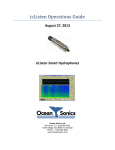
Lucy 3.5 User’s Guide Apr. 11, 2013 Ocean Sonics Ltd. Hill House, 11 Lornevale Road, Great Village, NS, B0M 1L0 Canada Phone: +1 902 655 3000 www.OceanSonics.com Table of Contents Table of Contents ........................................................................................................................................... i Table of Figures ............................................................................................................................................ iv 1 Using the LucyTM Software .................................................................................................................... 1 2 Getting started ...................................................................................................................................... 2 3 2.1 Starting the Program ..................................................................................................................... 2 2.2 Using Lucy ..................................................................................................................................... 2 Main Display.......................................................................................................................................... 3 3.1 3.1.1 Waveform Chart.................................................................................................................... 4 3.1.2 Guest Sensor Chart ............................................................................................................... 5 3.1.3 Single FFT Chart..................................................................................................................... 6 3.1.4 Correlation Chart................................................................................................................... 6 3.1.5 Spectrum Chart ..................................................................................................................... 7 3.2 Viewing the Spectrum Chart ......................................................................................................... 8 3.2.1 Size ........................................................................................................................................ 8 3.2.2 Spectrum Reference.............................................................................................................. 8 3.2.3 Ambient Noise Cancellation .................................................................................................. 8 3.2.4 Spectrum Control Box ........................................................................................................... 9 3.3 4 Charts ............................................................................................................................................ 4 General Controls ......................................................................................................................... 10 3.3.1 Scanning Controls ............................................................................................................... 10 3.3.2 Unit Status Controls ............................................................................................................ 10 3.3.3 Screenshot Controls ............................................................................................................ 11 3.3.4 Audio Playback .................................................................................................................... 11 3.3.5 Other Displays ..................................................................................................................... 11 Setup ................................................................................................................................................... 13 4.1 Link Setup .................................................................................................................................... 14 4.1.1 Manual Link Setup............................................................................................................... 14 4.1.2 Port Search .......................................................................................................................... 15 4.1.3 Additional options ............................................................................................................... 15 Lucy 3.5 User’s Manual © Apr. 11, 2013 i 4.2 Lucy Setup ................................................................................................................................... 16 4.3 icListen LF Setup .......................................................................................................................... 18 4.3.1 Data Collection .................................................................................................................... 19 4.3.2 Gain ..................................................................................................................................... 19 4.3.3 Bandwidth ........................................................................................................................... 19 4.3.4 Internal Logging .................................................................................................................. 20 4.3.5 Internal Time ....................................................................................................................... 20 4.3.6 FFT Processing ..................................................................................................................... 21 4.4 5 6 icListen HF Setup ......................................................................................................................... 22 4.4.1 Data Collection Mode ......................................................................................................... 23 4.4.2 Log File Length .................................................................................................................... 23 4.4.3 Internal Time ....................................................................................................................... 23 4.4.4 Bandwidth ........................................................................................................................... 24 4.4.5 Data Format (Advanced) ..................................................................................................... 24 4.4.6 Gain (Advanced) .................................................................................................................. 24 4.4.7 Duty Cycling......................................................................................................................... 25 4.4.8 Spectrum Processing ........................................................................................................... 25 4.4.9 Logging Delay ...................................................................................................................... 26 File Replay – Offline Operation ........................................................................................................... 27 5.1 Lucy TXT Replay........................................................................................................................... 27 5.2 Wav Replay ................................................................................................................................. 28 5.3 icListen FFT Replay ...................................................................................................................... 28 File Utility ............................................................................................................................................ 29 6.1 File Operations ............................................................................................................................ 30 6.2 Updates ....................................................................................................................................... 31 6.2.1 7 Firmware Updating ............................................................................................................. 31 Epoch Triggering ................................................................................................................................. 32 7.1 Select Event Trigger .................................................................................................................... 33 7.2 Trigger Conditions ....................................................................................................................... 34 7.3 Event Hold ................................................................................................................................... 34 7.4 Event Actions .............................................................................................................................. 35 7.4.1 icListen LF Event Actions ..................................................................................................... 35 Lucy 3.5 User’s Manual © Apr. 11, 2013 ii 7.4.2 icListen HF Event Actions .................................................................................................... 36 7.4.3 Lucy Event Actions .............................................................................................................. 36 7.5 Lucy Correlation Trigger .............................................................................................................. 36 7.6 Epoch Stream/Message Display .................................................................................................. 37 7.7 Event Active Time ....................................................................................................................... 39 8 Cross Correlation................................................................................................................................. 40 9 Runtime Logs....................................................................................................................................... 41 9.1 Job History File ............................................................................................................................ 41 9.2 Job Status File.............................................................................................................................. 42 10 FAQs ................................................................................................................................................ 43 Glossary ....................................................................................................................................................... 46 Lucy 3.5 User’s Manual © Apr. 11, 2013 iii Table of Figures Figure 3-1: Lucy Main Display ....................................................................................................................... 3 Figure 3-2: Waveform Chart ......................................................................................................................... 4 Figure 3-3: Time Trace Options ..................................................................................................................... 4 Figure 3-4: Guest Sensor Chart ..................................................................................................................... 5 Figure 3-5: Guest Sensor Options ................................................................................................................. 5 Figure 3-6: Single FFT Chart .......................................................................................................................... 6 Figure 3-7: Correlation Chart ........................................................................................................................ 6 Figure 3-8: Spectrum Chart ........................................................................................................................... 7 Figure 3-9: Spectrum Reference Options...................................................................................................... 8 Figure 3-10: Noise Cancellation Options....................................................................................................... 8 Figure 3-11: Active Calibration...................................................................................................................... 8 Figure 3-12: Spectrum Control Box ............................................................................................................... 9 Figure 3-13: Scanning Inactive .................................................................................................................... 10 Figure 3-14: Scanning Active ....................................................................................................................... 10 Figure 3-15: Enquire Response Example..................................................................................................... 10 Figure 3-16: Screenshot Controls................................................................................................................ 11 Figure 3-17: Current Details ........................................................................................................................ 11 Figure 3-18: Job Details ............................................................................................................................... 12 Figure 3-19: Left Sample Time .................................................................................................................... 12 Figure 3-20: Logging Comment and File ..................................................................................................... 12 Figure 4-1: Setup Options ........................................................................................................................... 13 Figure 4-2: Serial/USB Link Tab ................................................................................................................... 14 Figure 4-3: Ethernet Link Tab ...................................................................................................................... 14 Figure 4-4: Lucy Setup Tab .......................................................................................................................... 16 Figure 4-5: icListen LF Setup Tab................................................................................................................. 18 Figure 4-6: FFT Processing Settings ............................................................................................................. 21 Figure 4-7: icListen HF Setup Tab ................................................................................................................ 22 Figure 4-8: icListen HF Duty Cycling Setup .................................................................................................. 25 Figure 4-9: Spectrum Processing Settings................................................................................................... 25 Figure 4-10: Logging Delay .......................................................................................................................... 26 Figure 5-1: Replay Options .......................................................................................................................... 27 Figure 5-2: Replay Options .......................................................................................................................... 27 Figure 5-3: Example Replay Panel ............................................................................................................... 28 Figure 6-1: File Utility Button ...................................................................................................................... 29 Figure 6-2: File Utility Panel ........................................................................................................................ 29 Figure 6-3: File Options Example ................................................................................................................ 30 Figure 6-4: Progress Panel .......................................................................................................................... 30 Figure 6-5: Password Prompt ...................................................................................................................... 31 Figure 6-6: Critical Stage Warning .............................................................................................................. 31 Figure 7-1: Epoch Overview ........................................................................................................................ 32 Lucy 3.5 User’s Manual © Apr. 11, 2013 iv Figure 7-2: Epoch Setup Panel .................................................................................................................... 33 Figure 7-3: Select Event Trigger .................................................................................................................. 33 Figure 7-4: Trigger Conditions..................................................................................................................... 34 Figure 7-5: Event Hold................................................................................................................................. 34 Figure 7-6: Event Actions ............................................................................................................................ 35 Figure 7-7: Correlation Trigger .................................................................................................................... 36 Figure 7-8: Epoch Message Display............................................................................................................. 37 Figure 7-9: Active Time Setup ..................................................................................................................... 39 Figure 7-10: Active Time Messages............................................................................................................. 39 Figure 10-1: Lucy chart selection ................................................................................................................ 44 Lucy 3.5 User’s Manual © Apr. 11, 2013 v 1 Using the LucyTM Software The software used to talk to the icListen family of instruments is called Lucy. It is a PC program that presents data to the operator in a graphical and numerical format. The interaction of the software has been designed for field operations personnel, making it highly task focused. This document outlines the operation of the Lucy 3.5 software. Lucy 3.5 User’s Manual © Apr. 11, 2013 1 2 Getting started This section describes how to start the program and connect to an icListen unit. 2.1 Starting the Program If the software is not yet installed, run the Lucy installer provided with your icListen. Start-up of Lucy, as with other Windows applications, can be done from the Windows ‘Start’ menu, or a shortcut can be created to start directly from the desktop. It can be found on the start menu under: Start->All Programs->Ocean Sonics->Lucy. It is important to note that Lucy remembers the ‘state’ of the program as it is being used. This means that if the program must be stopped for some reason, settings and options are remembered, saving the operator from the worry of having to reconfigure those settings whenever the program is started. One or two settings are not remembered, by design, at startup to prevent possible confusion. Currently the noise filter is turned ‘off’ at startup, regardless of its previous status. 2.2 Using Lucy Lucy can be used in both online and offline mode. The main mode is online mode, which includes a connection to an icListen instrument. In this mode all options applicable to the connected instrument are available, including collecting and logging new data in real time. For instructions on how to connect to an icListen see the Link Setup section. Offline mode is used to replay previously logged files, logged either in Lucy or inside an icListen unit. All data viewing options are available while replaying files. Epoch triggering is also available on replayed data. For more details on offline operation, see the File Replay – Offline Operation section. Lucy 3.5 User’s Manual © Apr. 11, 2013 2 3 Main Display The main display contains two charts, and the controls needed during offline/online operation. This is the screen that appears at program start-up. This section details the display options and their controls. Figure 3-1: Lucy Main Display Lucy 3.5 User’s Manual © Apr. 11, 2013 3 3.1 Charts The display contains up to two charts. There are dropdown menus to the right of each chart position to select which charts are visible. There are 5 chart options in Lucy. The upper chart can be set to Wave, Single FFT, Guest Sensor, or Correlation, and the lower chart displays FFT Spectrum data. If either of the charts is set to off, the other chart will fill the display. All charts are updated at the refresh rate specified in the Lucy Setup panel. 3.1.1 Waveform Chart Figure 3-2: Waveform Chart The waveform chart shows recent waveform data in volts. The waveform corresponds to the sound pressure sensed at the hydrophone, at the sample rate shown in the upper left corner. The time scale of the chart is also shown in the upper left corner in milliseconds per division. This chart is made up of 10 divisions. The Waveform chart options are seen in the figure below. The ‘Scan’ box enables the collection of waveform data from the icListen. Figure 3-3: Time Trace Options There are two options for the y-axis size Auto Scale Manually Scale The advantage of auto scale is that the displayed data is never clipped. However this can make interpreting the data difficult, since the scale may change every time the display is refreshed. Manually Scaling makes the y-axis scale constant, allowing for better comparative readings. Lucy 3.5 User’s Manual © Apr. 11, 2013 4 The AC field displays the average AC voltage component of the measured signal, in RMS. Advanced: The DC field must be enabled on the Lucy Setup panel in advanced mode. This displays the DC offset (in volts) which has been removed from the displayed data. This chart will display the fading history of the previous waveform data results. The most recent data is plotted in green, and as the data ages it fades to dark blue before disappearing. 3.1.2 Guest Sensor Chart Figure 3-4: Guest Sensor Chart The guest sensor chart is a real time display, sharing its x-axis time scale with the Spectrum Chart. Guest Sensor data is stored in the Lucy FFT files when logging is enabled. The options box for the Guest Sensor is seen in the following figure. Figure 3-5: Guest Sensor Options The prominent number displays the most recent Guest Sensor value. The limit moves the alarm limit line on the chart (purple line on the display). When the value exceeds the alarm limit, an audible alarm sounds. The sensor value must cross back below the alarm limit for multiple samples, before another value that exceeds the alarm limit can sound a new alarm. Checking the ‘Scan’ box will request Guest Sensor data from the instrument. Lucy 3.5 User’s Manual © Apr. 11, 2013 5 3.1.3 Single FFT Chart Figure 3-6: Single FFT Chart The Single FFT chart displays the most recently received FFT data. This data will correspond with the most recent data on the Spectrum Chart. The x-axis of this chart is the frequency range, which varies based on the sample rate selected. Frequency may also be plotted on a logarithmic scale, by using the log scale option to the right of the spectrum chart. The y-axis of the chart is the amplitude. This is scaled using the reference scaling options in the lower left of the display. These scaling options are detailed in the Spectrum Reference section. There is also an auto-scale option selectable on the right of the chart. Like the Waveform chart, this chart will display the fading history of the previous FFT results. New data is plotted in green, and fades to dark blue before disappearing. 3.1.4 Correlation Chart Figure 3-7: Correlation Chart The correlation chart shows the result of the Spectrum (FFT) data normalized and summed with the Correlation signal from a loaded correlation file. The x-axis of the chart is time, and is aligned with the Spectrum chart below. The new data points correspond with the correlation of the new spectrum data, seen on the spectrum chart. See Cross Correlation for more details. Lucy 3.5 User’s Manual © Apr. 11, 2013 6 3.1.5 Spectrum Chart Figure 3-8: Spectrum Chart The Spectrum chart displays the Fast Fourier Transform (FFT) of the data returned by icListen. This is a 3D chart showing time on the x-axis, frequency on the y-axis, and intensity of the signal on the z-axis. Lucy 3.5 User’s Manual © Apr. 11, 2013 7 3.2 Viewing the Spectrum Chart This section describes how to configure the Spectrum Chart to get the best display. 3.2.1 Size The x-axis (time axis) of the spectrum chart is controlled by the “Size” field, in the bottom right of the chart. Modifying this setting, the operator selects how much data they wish to view, in minutes. This allows the user to closely view the newer data, or display a longer overview of the data. The maximum size for this value varies depending on the FFT averaging settings and the sample rate. 3.2.2 Spectrum Reference The Spectrum chart lets the operator make detailed measurements from the display. The chart can display spectral data in µV or µPa, as required. The chart baseline reference can be adjusted in 10 dB steps above 0 dB, which may otherwise clutter the display with noise floor data. Figure 3-9: Spectrum Reference Options The transition from one colour to the next is assigned a value, according to the coloured numbers in the lower left. The range can be changed by clicking the up or down arrows to give the best display of events in the chart. Note that once selected, the arrow keys on the PC keyboard can be used to ‘animate’ the chart to help in identifying subtle events. 3.2.3 Ambient Noise Cancellation A powerful operational tool comes with Lucy that allows the operator to model the ambient noise environment, and then remove that noise while looking for a specific signal. When enabled, the current ambient noise model is used to remove unwanted signal. The noise model is stored, allowing it to be used over extended periods. Figure 3-10: Noise Cancellation Options To create a new ambient noise model, click the ‘Start Cal’ button, and watch the elapsed time display. When at least 30 seconds of time has passed, click the ‘Stop Cal’ button. Figure 3-11: Active Calibration Lucy 3.5 User’s Manual © Apr. 11, 2013 8 This new noise model is stored, and used for noise cancellation. These calibrations are remembered and reloaded when Lucy is started, to allow the same models to be used through multiple jobs if desired. 3.2.4 Spectrum Control Box To the right of the Spectrum Chart is the control box that controls some of the chart’s settings. This is shown in the following figure. Figure 3-12: Spectrum Control Box Checking the ‘Scan’ box enables collection of the Spectrum data. The frequency axis can be displayed logarithmically by checking the ‘Log Scale’ box. This provides greater resolution at low frequencies. The ‘Signal Power’ is calculated by combining the spectral data for each sample over the full spectrum. This represents the total power over any sample. Lucy 3.5 User’s Manual © Apr. 11, 2013 9 3.3 General Controls This section will detail the general controls of Lucy. 3.3.1 Scanning Controls The data collection process begins when the ‘Start’ button is clicked. Note that whenever scanning starts, the charts are cleared. When scanning is inactive, the ‘Start’ button is visible, and the ‘Pause’ and ‘Stop’ buttons are hidden. When scanning is active, the ‘Stop’ and ‘Pause’ buttons are visible, and the start button is hidden. Figure 3-13: Scanning Inactive Figure 3-14: Scanning Active When scanning is paused and resumed, a black section is added to the display equal to the duration of the pause, and the chart is continued at the appropriate point in the chart. The “Reset Charts” option is used to clear the displays. 3.3.2 Unit Status Controls The Unit Status shows the status of icListen, and any link issues that occur when active. When testing icListen, clicking the ‘Enquire’ button returns the status of the link and the instrument. This is the most direct way of testing the instrument. Messages stay in the display area until they are cleared or a newer message is displayed. Messages can be cleared by pressing the ‘Clr’ button. All units report the Temperature and Humidity in the status field. icListen HF (hardware rev. 2 and newer) report the battery charge, and charging state (a lightning bolt through the battery indicates that the battery is charging). Figure 3-15: Enquire Response Example Lucy 3.5 User’s Manual © Apr. 11, 2013 10 3.3.3 Screenshot Controls To the right of the unit status controls is the screenshot area, shown in the figure below. Figure 3-16: Screenshot Controls The screenshot controls have two parts. The left button selects the folder for the screenshots to be placed, and the right button takes the screenshot. The name of the screenshot file is Screenshot_YYMMDD_hhmmss, where: YY = Year MM = Month DD = Day hh = Hour mm = Minute ss = Second 3.3.4 Audio Playback This section describes the audio playback function of Lucy. Lucy has the ability to play the audio contained in live waveform data, as well as replayed .wav files. This option is available for little endian (default) waveform data at a sample rate of 32 kS/sec and below. Audio playback can be enabled by clicking the “Audio Enabled” check box. Audio playback in Lucy is always 16 bit, regardless of the original waveform data resolution. The volume of the audio playback is controlled by the Spectrum Reference controls. The red value in the FFT display corresponds to the maximum audio amplitude which can be played back. To maintain accurate audio playback the FFT display should be adjusted so that all displayed data is below the red level. The speaker volume in Windows will also affect the playback volume. 3.3.5 Other Displays This section describes the remaining items on the main panel. Figure 3-17: Current Details In the top right corner there is a Current Details box (shown in the figure above), which displays the current date, time and the connected unit’s serial number. Lucy 3.5 User’s Manual © Apr. 11, 2013 11 Figure 3-18: Job Details Along the top of the main display there are the job details (‘Client’, ‘Job ID’ and ‘Personnel’), which are shown in the figure above. These are filled in on the Lucy Setup tab (see Lucy Setup). Figure 3-19: Left Sample Time The lower left corner of the spectrum graph contains a small box which lists the time of the oldest sample on the display. Figure 3-20: Logging Comment and File Below the lower right corner of the spectrum chart, there are the ‘Logging Comment’ and the ‘Log Data File’ fields. The logging comment is entered by the user, and is written into the Lucy TXT log files. The log data file displays the current file being logged into, or currently replayed. Lucy 3.5 User’s Manual © Apr. 11, 2013 12 4 Setup At the beginning of each project or job, the setup of the program and instrument should be checked and changed as required. The box below is found in the lower right-hand corner of the display. This is shown in the following figure. Figure 4-1: Setup Options The setup panel is divided into tabs for individual configuration types. Only configurations tabs applicable to the connected unit are displayed. Advanced Settings: Many setup tabs also contain some settings for advanced users. These options can be revealed by selecting ‘Advanced’ mode, in the lower left corner of the setup panel. All advanced settings will be labeled ‘Advanced’ in this section. This section covers: Link Setup Lucy Setup icListen LF Configuration Setup icListen HF Configuration Setup For Epoch event setup see the Epoch Triggering chapter. Lucy 3.5 User’s Manual © Apr. 11, 2013 13 4.1 Link Setup To connect to an icListen instrument, select the ‘Link’ option, to bring up the Link Panel. There are two selectable connection types: Serial/USB and Ethernet, shown respectively below. Figure 4-2: Serial/USB Link Tab Figure 4-3: Ethernet Link Tab Link Setup can either be done manually, or automatically. 4.1.1 Manual Link Setup If the connection information for your instrument is known, enter the details and press ‘Manual Connect’. If successful, the details of the connected instrument will be displayed beneath the setup. Lucy 3.5 User’s Manual © Apr. 11, 2013 14 4.1.2 Port Search Port Search is used to search for units by scanning ports. For Serial/USB connections, port search scans from port 1 to port 100, displaying all of the discovered units in the box on the right of the display. For Ethernet connections, Port Search searches the ports commonly used for icListen at the entered IP/Web address. Ports 23, 50000, 50100, 50200, 50300, 50400, and 50500 are searched. Ports 23 and 50000 are the default command and control ports for icListen LF and HF. The remaining ports are commonly used when connecting to multiple units at the same IP/Web address via the port forwarding settings of a router. See the FAQ for more details on this configuration. 4.1.3 Additional options Reboot/Shutdown: When a connection is established to a unit which supports the reboot command (icListen HF units, icListen LF units with firmware 2.5 or greater), there is an option to reboot/shutdown the unit. When this option is selected and the icListen is externally powered, the unit will reboot. If the unit is not externally powered, the unit will power off until the next time external power is applied. Disconnect: When a connection is established to a unit, there is an option to disconnect from the unit. This closes Lucy’s connection to the unit. Advanced: Serial/USB units have the ability to set a custom timeout. Typically Lucy selects the timeout value which is judged to be appropriate. However, when using a radio modem, or running at a very fast data rate, it may be necessary to adjust the timeout for better performance. Advanced: Serial icListen LF units have the ability to change the baud rate of the connection. With a connection established at the current baud rate, select the new baud rate and click update. This will change the baud rate of the unit and reconnect at the new baud rate. If a connection is not established at the new baud rate, both the icListen LF and Lucy will revert to the previous baud rate and re-establish a connection. Lucy 3.5 User’s Manual © Apr. 11, 2013 15 4.2 Lucy Setup Figure 4-4: Lucy Setup Tab The ‘Lucy Setup’ tab is responsible for the configuration of logging within Lucy, and for display options. Job details and replay epoch settings are also set on the Lucy setup tab. The job details consist of the ‘Client Name’, ‘Job ID’, and ‘Personnel’. These values, once accepted, update the values along the top of the main display. These are useful for keeping track of the details of a job, as they appear in both the screenshots and Lucy txt log files. The refresh rate option allows users to reduce the CPU resources used, by reducing the number of display updates performed by Lucy. Reducing the refresh rate may cause less data to be displayed, but does not cause any data to be lost or discarded. The Select Correlation File option is used to load a correlation file. When a correlation file is loaded, the file name is shown below the select button, as seen with “Porpoise – Corr 8.txt” in the screenshot above. For more details on the use of this file see Cross Correlation. The Logging options relate to Lucy logging only. For instrument logging options see icListen LF Setup or icListen HF Setup. Lucy can perform three types of logging simultaneously: Spectrum Data (FFT) Waveform Data (Time Series) Epoch Message Data The FFT logging stores data in a human readable TXT log format, which can be imported into a spreadsheet. These files also include guest sensor, temperature, and humidity data, if available. Lucy 3.5 User’s Manual © Apr. 11, 2013 16 Waveform data is logged in the form of .wav audio files. These files are playable in any standard audio player, such as Audacity. Epoch message data is logged in human readable TXT logs, which can be imported into a spreadsheet. There are two types of epoch message logs which can be configured on the Lucy setup panel. These are the Instrument epoch stream log and the replay epoch stream log. The instrument epoch stream consists of the epoch messages that arrive from a connected icListen HF. The replay epoch stream log consists of the epoch messages and active time messages from the Lucy configured epoch triggers. Lucy epoch triggers for replayed data can also be configured from the Lucy Setup panel. Epoch trigger files may also be loaded or saved. For more details on configuring epoch triggers see Epoch Triggering. Advanced: The scan rate option adjusts the rate at which Lucy requests data from an icListen. Lucy typically sets this to an optimal rate for the current instrument configuration. This option overrides the calculated rate. It is important to note that if the scan rate is set lower than the incoming data rate, then data will be lost. Advanced: The option to show the DC voltage, when checked, enables the DC offset display for Time Series data on the main Lucy display. Lucy 3.5 User’s Manual © Apr. 11, 2013 17 4.3 icListen LF Setup Figure 4-5: icListen LF Setup Tab The icListen LF Setup tab displays the current configuration of icListen LF, and allows this configuration to be updated. The current configuration of the connected icListen is displayed on the icListen LF setup tab as soon as the tab is opened. The following icListen LF settings can be changed: Data Collection Gain Bandwidth Internal Logging Internal Time FFT Processing Lucy 3.5 User’s Manual © Apr. 11, 2013 18 4.3.1 Data Collection The Data collection setting has two options, which can be set independently for both waveform and spectrum data. These options are: Always o Data of this type is always sent to Lucy when scanned. On Epoch Trigger o Data of this type is sent to Lucy when scanned, only when an Epoch event has triggered (see Epoch Triggering). Data Off o Data of this type will not be collected by Lucy. 4.3.2 Gain The Gain is used to increase the sensitivity of the icListen. Gain values are in steps of 6 decibels (dB) and range from 12 to 24. For best performance, Ocean Sonics recommends using a gain value of 12dB. Advanced: Gain options in advanced mode range from 0-72dB. 4.3.3 Bandwidth The bandwidth is the range of frequencies available. The higher the desired bandwidth, the higher the sample rate required. The possible values are: Bandwidth (Hz) 100 200 Sample Rate (Samples/sec) 250 500 400 1000 800 2000 1600 4000 3200 8000 6400 16000 Lucy 3.5 User’s Manual © Apr. 11, 2013 19 4.3.4 Internal Logging The internal logging selection allows the user to set the type of logs that the icListen unit will create. The options are: .wav files o Standard audio file format. Playable in most 3rd party audio players. o Note: .wav logging can only be performed up to 1600Hz bandwidth setting. .FFT logs o Ocean Sonics FFT format files. The format of these files can be found in the Ocean Sonics logging format document. Triggered logging o Logging is done based on Epoch event triggers. o Note: Triggered logging is only available up to 1600Hz bandwidth setting. All logged files can be replayed in Lucy (see File Replay). 4.3.5 Internal Time Using the ‘Sync Time’ button, the internal time of the icListen can be set to match that of the PC running Lucy. Setting the time is required, for accurate file creation times of the internal logs. Lucy 3.5 User’s Manual © Apr. 11, 2013 20 4.3.6 FFT Processing Figure 4-6: FFT Processing Settings The processing performed on frequency domain data can be configured by adjusting the accumulation type, and the sliding window overlap. Three types of FFT processing are available to icListen LF. These are Mean, Peak, and Filter. The sliding window overlap can be adjusted for any of these processing types. For “Mean” and “Peak” processing, the “Num Strings” field indicates the number of FFT data sets that are used for each processed result. For “Filter”, the “Num Strings” field is used both for determining how many FFT data sets must be processed before returning a result, and is used to determine the weighting factor (“Num Strings” / 3). If FFT accumulation mode is set to “Off”, no averaging is performed. Switching the accumulation mode to “Off” does not affect the sliding window overlap. For a more detailed description of how the FFT processing works, please refer to the icListen User Guide. Lucy 3.5 User’s Manual © Apr. 11, 2013 21 4.4 icListen HF Setup Figure 4-7: icListen HF Setup Tab The icListen HF Setup tab displays the current configuration of icListen HF, and allows this configuration to be updated. The current configuration of the connected icListen is displayed on the icListen HF setup tab as soon as the tab is opened. The following icListen HF settings can be changed: Data Collection Mode Log File Length Internal time Bandwidth Duty Cycling Data Format (Advanced) * Gain (Advanced) * Spectrum Processing Spectrum Reference Level (Advanced) Logging Delay *Note: Data Format and Gain are only available for HF release 14 and newer. Lucy 3.5 User’s Manual © Apr. 11, 2013 22 4.4.1 Data Collection Mode There are many available data collection modes. Waveform and spectrum data collection modes are set independently, and not all modes are available to each type of data. Available options are: Data Off o Data of this type is not sent to Lucy. Scan o Only available for spectrum data. o Data is available to be scanned over the command and control port, but is sent only by request. Stream o Available for both waveform and spectrum data. o Live data is streamed from icListen HF’s Streaming TCP port. Log Continuous o Available for both waveform and spectrum data. o All data of selected type is logged internally. o Spectrum data is also available to be scanned from the command and control port when logging is enabled. Log Duty Cycle o Only available for waveform data. o Data is logged internally for the selected duration, and then for the remainder of the cycle duration data is skipped. This cycle repeats continuously. Epoch o Available for both waveform and spectrum data. o Data is logged based on epoch trigger settings. Epoch & Log Duty Cycle o Available for waveform data only. o Data is logged based on epoch triggers and the duty cycle. This means data will be logged both during the cycle time, and if a trigger occurs. 4.4.2 Log File Length This feature allows the user to configure the length (in minutes) of files internally logged by the icListen unit. 4.4.3 Internal Time Using the ‘Sync Time’ button the internal time of the icListen can be set to match that of the PC running Lucy. Time synchronization should always be performed prior to applying the rest of the setup, as changing the time could affect when logging begins if a start delay is set. This is only an issue with Firmware 1.4 and earlier. Lucy 3.5 User’s Manual © Apr. 11, 2013 23 4.4.4 Bandwidth The bandwidth is the range of frequencies available. The higher the desired bandwidth, the higher the sample rate required. The possible values are: Bandwidth (Hz) 400 800 Sample Rate (Samples/sec) 1000 2000 1600 4000 3200 8000 6400 16000 12800 32000 25600 64000 51200 128000 102400 256000 204800 512000 4.4.5 Data Format (Advanced) The data format is adjustable when using waveform data. Data can be returned as 16 bit, 24 bit, or 32 bit, and in big or little endian. As the resolution of the hydrophone is 24 bit, the 32 bit setting will actually return 24 bit data packed into 32 bit (the low byte can be ignored for this data). Due to the fact that WAV files are defined as little endian, all requests for big endian logged data will also be modified to little endian before sending the setup to the instrument. Note: 512 kS/sec data can only be streamed/logged at 16 bits. Note: If not in advanced mode, the data format is automatically set to 24 bit Little Endian for sample rates 256 kS/sec and below, and 16 bit Little Endian data for 512 kS/sec. 4.4.6 Gain (Advanced) In icListen HF, the configurable gain setting applies digital gain to the waveform data. Gain is adjustable in steps of 6 dB, ranging from 0 dB to 48 dB. This setting can only be adjusted for 16bit data, where it can be used to increase the sensitivity of the unit to compensate for the reduced resolution. Note: If not in advanced mode, gain is automatically set to 0. Lucy 3.5 User’s Manual © Apr. 11, 2013 24 4.4.7 Duty Cycling Figure 4-8: icListen HF Duty Cycling Setup Duty cycling is available when waveform data is being logged. The logging cycle used is determined by the ‘Cycle Time’ and ‘Log Data Time’ fields. Data will be logged for the first “Log Data Time” minutes of the complete “Cycle Time”. In the screenshot above, this means that the first 10 minutes will be logged and the next 50 minutes will not, for the total of a 60 minute cycle. This cycle is repeated continuously. 4.4.8 Spectrum Processing Figure 4-9: Spectrum Processing Settings The processing performed on frequency domain data can be configured by adjusting the processing mode, and the spectrum update rate. Three types of FFT processing are available to icListen HF: Mean, Peak, and Filter. Lucy will adjust the processing settings based on the update rate. For a detailed description of how the FFT processing works, please refer to the icListen User Guide. Advanced: icListen HF returns spectral data relative to the Spectrum Reference Level, which is equal to the minimum spectral density measurement icListen can return. Ocean Sonics recommends maintaining this at -120dBV except whenever making low noise/low amplitude measurements. Lucy 3.5 User’s Manual © Apr. 11, 2013 25 4.4.9 Logging Delay Figure 4-10: Logging Delay The logging delay is used to set the time at which logging is started. This is applied to both waveform and FFT data logging. If “Enable Delay” is not selected then data logging starts immediately. In HF firmware 1.4 and earlier, any time sync must be done before this setting is applied in order to maintain the proper delay. Lucy 3.5 User’s Manual © Apr. 11, 2013 26 5 File Replay – Offline Operation Lucy provides the operator with the ability replay previously logged files including Files created by icListen in WAV, FFT, or TXT format Files created by Lucy while collecting real-time data from icListen The format of all of these files can be found in the icListen Log File Formats document. Select the ‘Replay’ button from the Lucy main panel to start the replay process. This will open a popup which allows selection of files. Multiple files may be selected. The files will be played in the order shown in the selection window. Files of different types may be played in the same sequence and the screen will be cleared when switching between file types. Figure 5-1: Replay Options A previously replayed file can be viewed once more by clicking the “Again” button, using the same settings. If multiple files have been replayed, pressing the “Again” button will play the most recently played file. The ‘icListen’ button is for the file utility which will be covered in the File Utility section. The speed of the replay is set with the ‘Replay Rate’ field. This can be ‘Real Time’, ‘Slow’, ‘Medium’ and ‘Fast’. The display is still updated at the set refresh rate during replay; however the amount of new data per refresh is changed by the replay rate. ‘Real Time’ is the rate which the data was initially displayed at, and the speed increases respectively from there. When a file is replaying, it may be paused or stopped using the controls shown below. Figure 5-2: Replay Options 5.1 Lucy TXT Replay Lucy TXT log files are stored in tab separated variable (TSV) form. These files can be viewed by a spreadsheet viewer (such as Excel) as well as through Lucy. When replayed, the data is displayed as it was when initially received. Lucy 3.5 User’s Manual © Apr. 11, 2013 27 Certain settings (such as noise cancelling and chart scaling) are viewing aids only, and are not stored with the data. Figure 5-3: Example Replay Panel On the replay panel the user has the ability to view the source of the file, which opens the file in the users default text editor. Once the ‘Replay’ button is pressed, the Replay Setup window disappears and the data starts to replay, at the selected rate. The Lucy TXT log files contain Spectrum and Guest Sensor data. 5.2 Wav Replay After pressing the Replay button on the main panel and selecting a .wav file, the file will immediately start to play. This includes the time series data, and also an FFT of the data at a rate of 4 FFTs per second. If the data is at a sample rate of 32kS/sec then the audio playback may be used. For more details on the audio playback see Audio Playback. Display enhancement tools may be used as usual. 5.3 icListen FFT Replay When an .FFT file is selected for replay, the file starts replaying immediately. These files only contain FFT data, and thus only the spectrum chart will contain data. The time series and guest sensor charts will either be blank or hidden, based on user settings. Display enhancement tools may be used as usual. Lucy 3.5 User’s Manual © Apr. 11, 2013 28 6 File Utility The file utility is available for the icListen LF. It is used to navigate through the instrument’s filing system, and allow the operator to retrieve or delete logged data files. Configuration files and instrument firmware may be updated here as well. Data from icListen HF is retrieved using SFTP/SCP through a program such as Filezilla, or through the web interface. The file utility is opened by pressing the ‘icListen’ button in the ‘Files’ section of the main display. Figure 6-1: File Utility Button Once the ‘icListen’ button is pressed, the file utility panel (shown below) will open. Figure 6-2: File Utility Panel Lucy 3.5 User’s Manual © Apr. 11, 2013 29 6.1 File Operations Once the file utility panel has opened, the last viewed directory structure will be displayed. If this is the first time the utility has been open since Lucy was started, the connected volumes will be displayed. Some important system files are hidden from view, to prevent accidental loss. To view the contents of a directory, double click the directory name and the contents will be requested and shown. To download a file/directory, double click on the file in the selection tree; or single click to make the options on the right available, for retrieving or deleting the selected file/directory. Figure 6-3: File Options Example Clicking ‘Delete’, deletes the file/directory permanently from icListen LF after a confirmation popup. For directories this may take some number of minutes, if there are a lot of files. Completion is confirmed when the cursor stops spinning. Clicking ‘Retrieve’ acquires the file/directory from the icListen LF to the PC. When in progress, the following panel appears, showing the progress of the retrieval for each individual file. Figure 6-4: Progress Panel Files are often retrieved in many packets, and may take a few minutes to retrieve. At any point during the process, the file retrieval can be cancelled. This will leave a partial file on the user’s computer, but will not harm the file in the icListen LF. Lucy 3.5 User’s Manual © Apr. 11, 2013 30 6.2 Updates Occasionally, the icListen LF instrument may need its firmware updated. This should only be done with assistance from Ocean Sonics. This section covers the process of updating the firmware. 6.2.1 Firmware Updating Care is required when updating the instrument firmware. First ensure that only valid icListen firmware is used during the update. Power must not be removed from the instrument during the update process. When the ‘Firmware’ button is pressed, a password prompt appears. Once the correct password is entered, a file select window opens. Figure 6-5: Password Prompt Once a firmware file is selected, the progress window appears. A second progress window appears during the verify stage. Before the final update step, there is a final warning and chance to cancel. Figure 6-6: Critical Stage Warning Once this is accepted the critical operation occurs in the icListen LF, and confirmation of completion is displayed. To have the update apply, the icListen LF unit must be power cycled (power off, wait 10 seconds, power on). Once the icListen LF unit reboots, an enquire command should list the new firmware version. Lucy 3.5 User’s Manual © Apr. 11, 2013 31 7 Epoch Triggering In Epoch mode, icListen LF/HF can be configured to detect specific signals in the real-time data, and perform a number of tasks based on those signals. When replaying data, Lucy can also be configured to detect epochs. Lucy and icListen can each check the data for up to 5 independent triggers as shown in the following figure. Figure 7-1: Epoch Overview Each epoch event consists of 3 parts as detailed in the figure above. This section will cover the setup and removal of epochs from icListen or Lucy. Note: It is important to complete the icListen LF configuration before the Epoch settings, as some of the Epoch settings (frequencies, durations and logging) are dependent on the unit’s configuration. For icListen HF any trigger out of frequency range will be disabled, all others will be adjusted for the new settings automatically, to maintain the same trigger. Note: Lucy may round entries to the nearest values supported by icListen. Lucy 3.5 User’s Manual © Apr. 11, 2013 32 Figure 7-2: Epoch Setup Panel The epoch setup tab is divided into 3 sections: Trigger Conditions, Event Hold, and Event Actions. 7.1 Select Event Trigger Figure 7-3: Select Event Trigger The event trigger which is being modified is selected from the Job Setup panels. All active epochs have a green LED beside them, while all disabled epochs have a black LED beside them. The numbered buttons bring up the epoch panel for the selected epoch event. Note: icListen LF does not maintain event numbers when enquired. This means that if you have 3 triggers and you remove number 2, and then upon enquire, only positions 1 and 2 will be filled. icListen HF and Lucy maintain trigger numbering. Lucy 3.5 User’s Manual © Apr. 11, 2013 33 7.2 Trigger Conditions Figure 7-4: Trigger Conditions The trigger conditions section is where users set up the details of a particular epoch. These settings are what the icListen checks the new data against to decide if an event has occurred. The event frequency range is the min and max frequencies of the range checked for the other signal conditions. The signal conditions are the amplitude of the signal to check against (in µPa), the duration that the signal must be present/gone for (in seconds), and the condition field which must be met (whether we are checking for a signal to become present (Greater) or disappear (Lower)). 7.3 Event Hold Figure 7-5: Event Hold The event hold is the duration (in seconds) which the event actions will remain after the trigger signal has ended. Lucy 3.5 User’s Manual © Apr. 11, 2013 34 7.4 Event Actions Figure 7-6: Event Actions The event actions are the tasks performed by the icListen when a trigger occurs. 7.4.1 icListen LF Event Actions The options for actions in icListen LF are: FFT Message o Prepares a message containing FFT data for Lucy to retrieve when scanning. o Note: icListen must be configured to “On Epoch Trigger” mode for FFT data. Wav Message o Prepares a message containing Wave data for Lucy to retrieve when scanning. o Note: icListen must be configured to “On Epoch Trigger” mode for Wave data. Trigger Pulse o Sends a pulse on the sync wire pair. o Note: icListen must be equipped with the optional sync interface for a pulse to be sent. Log FFT data o Logs an .FFT file containing the FFT data during the trigger’s duration. o Note: icListen must be configured to “On Epoch Trigger” mode for logging. o Note: If another trigger is already logging Wave data, FFT logging will not occur. Log Wav data o Logs a .wav file containing the Wav data during the trigger’s duration. o Note: icListen must be configured to “On Epoch Trigger” mode for logging. o Note: If another trigger is logging .FFT files, the logging of the .FFT file will be stopped and the .Wav logging will begin instead. All of these actions can be performed on the same trigger with the exception that only 1 type of logging is permitted at a time. Note: Triggered logging is not permitted above a bandwidth setting of 1600Hz (4kS/sec Sample Rate). Lucy 3.5 User’s Manual © Apr. 11, 2013 35 7.4.2 icListen HF Event Actions The options for actions in icListen HF are: Log FFT data o Logs a .TXT file containing the FFT data during the trigger’s duration. o Note: icListen’s FFT setup must be configured to “Epoch” mode. Log Wav data o Logs a .wav file containing the Wav data during the trigger’s duration. o Note: icListen’s Wave setup must be configured to “Epoch” or “Epoch & Log Duty Cycle” mode. Epoch Messages (Always active) o Logged and streamed by icListen HF. For icListen HF, these actions may be performed simultaneously. 7.4.3 Lucy Event Actions The options for actions in Lucy are: Epoch Messages (Always active) o Can be Logged and Displayed by Lucy. 7.5 Lucy Correlation Trigger Figure 7-7: Correlation Trigger The Lucy correlation trigger is an epoch trigger, which checks if the correlated data has exceeded the configured threshold. This threshold can be set on the main panel when the correlation chart is active, as shown above. This trigger is only available on Lucy Replayed data. For more details on the correlation see Correlation. Lucy 3.5 User’s Manual © Apr. 11, 2013 36 7.6 Epoch Stream/Message Display Figure 7-8: Epoch Message Display The epoch stream is a message stream which sends an ASCII string every time an event is triggered. This panel is opened from the “Epoch Stream” button which appears on the right side of the main display when an epoch is active in the unit or Lucy. This feature is available for icListen HF and replayed data in Lucy. The returned string includes the timestamp in the format YYYY-MM-DD HH:mm:SS, which is Y=year, M=month, D=day, H=hour, m=minutes, S=seconds. The unit’s serial number is identified by the U ####, where # is the serial number. The number of the Epoch which triggered is identified by Epoch #, where # is the trigger number. The data sequence number is identified by Seq #, where # is the sequence number of the data point at which the trigger occurred. Lucy 3.5 User’s Manual © Apr. 11, 2013 37 The frequency range, test, amplitude, and duration being checked by the trigger are shown at the end of the line. The test is currently ‘>’ for greater than, and ‘<’ for less than the selected amplitude. For correlation triggers this will read “Cross Corr > x” where x is the correlation limit of the trigger. When Lucy replay epoch detection is being used, there are epoch status indicators in the lower right corner of the Epoch Message panel. These indicators are numbers for each epoch which change colour for the status of the trigger. The colours are: Blue o Green o Yellow o White o Trigger signal present, pending duration. Trigger active Trigger signal gone, pending extension period. Trigger inactive Lucy 3.5 User’s Manual © Apr. 11, 2013 38 7.7 Event Active Time Figure 7-9: Active Time Setup The Lucy replay epoch detection can also calculate the percentage of time during a set duration where the trigger signal is present. One resulting line for each active epoch is sent as an epoch message to be both displayed and logged at the end of the duration, as shown below. The active time is shown as a percentage, such as “Active 23%”. The active time is calculated using the number of FFTs during the duration which contain the desired signal, divided by the total number of FFTs during the duration, and multiplied by 100 to form a percentage. Figure 7-10: Active Time Messages Lucy 3.5 User’s Manual © Apr. 11, 2013 39 8 Cross Correlation In Lucy, the cross correlation mode takes a loaded in FFT correlation file, and performs a cross correlation on the live or replayed FFT data. The correlation file is the same format as an FFT txt log. When an FFT text log is loaded for the correlation file, the first FFT result is used for the cross correlation. The correlation file is loaded from the Lucy Setup page. When FFT data is received by Lucy, the new data is normalized and summed with the normalized signal from the correlation file. The result is then graphed. For replayed data, the correlation result can also be used for epoch triggering. See Cross Correlation Chart for more details on the graphed data. Lucy 3.5 User’s Manual © Apr. 11, 2013 40 9 Runtime Logs During operation, Lucy stores two additional files. These are the Job History file and Job Status file. These files are located in “C:\Users\*******\AppData\Roaming\Lucy” where ***** is the username of the computer. Note, the AppData directory is hidden by default, and therefore Windows settings may need to be changed to access these files. 9.1 Job History File The Job History File logs the current job details. This includes the date/time, the instrument’s serial number and firmware version, the version of Lucy being used, current temperature and humidity, the current log file name, and the entered Client, Job ID and Personnel. This file is updated whenever scanning is started. Example Job History File Excerpt (generally viewed as a spreadsheet): Date Time Data Serial and FW SW Temp Hum. 18/11/10 13:51:21 Acou/Time unit 504 v2.1.02 Lucy V2.1.0 24.2 C 29.4 18/11/10 14:11:00 Acou/Time unit 504 v2.1.02 Lucy V2.1.0 23.8 C 30.4 18/11/10 14:15:57 Acou/Time unit 504 v2.1.02 Lucy V2.1.0 24.2 C 29.4 DataFile Client JobId Personnel Lucy1.TXT Lucy "Lucy" "Lucy" Lucy1.TXT Lucy "Lucy" "Lucy" Lucy1.TXT Lucy "Lucy" "Lucy" Lucy 3.5 User’s Manual © Apr. 11, 2013 41 9.2 Job Status File The Job Status File logs the status bar updates to ensure none are missed. This includes events such as device configurations, data errors, and file system usage. To ensure the file doesn’t get too large, if a connection is lost for an extended period of time, the data error will only be recorded every 30 seconds. In this scenario it will be recorded when a successful connection is again established. Example Job Status File Excerpt: Date Time – Status 18/11/10 14:31:58- Scanning Started 18/11/10 14:32:00- Directory Command Sent 18/11/10 14:32:07- icListen Configured Successfully 18/11/10 14:32:10- Scanning Stopped 18/11/10 14:32:11- Application Shutdown Lucy 3.5 User’s Manual © Apr. 11, 2013 42 10 FAQs This section will go through some common questions and their answers. Q. Why didn’t “Port Search” find anything? A. Check to verify that your unit is connected to your computer properly and is powered. For Ethernet units, verify that the correct IP address is entered. For an Ethernet icListen HF, Ocean Sonics recommends using the application Marco, which is included with the instrument, to detect/configure the unit’s IP address. Q. Why does my IP address not work for connecting to icListen? A. Make sure that there are no leading 0’s in any of the address fields. For example, an address of 10.10.10.1 should not be typed as 010.010.010.001. This is because leading 0’s will cause the address to be interpreted as base 8 (octal) instead of base 10 (010 is treated as 8, not 10). Q. How can I test icListen is functioning properly before deployment? A. Connect icListen to your computer and an appropriate power source and run Lucy. Once Lucy is started, click to open the Link panel (bottom right). On the Link Panel click Port Search or enter the correct Port and Baud Rate (or Port and IP Address for Ethernet). The enquire status should report “Ready”. If desired, some data can be collected to further test the unit by pressing the start button at the top left of the main panel. Q. I am connected to my unit, but cannot get data, how can I collect data? A. While connected to the instrument, in the setup panel, check to ensure that the unit is configured to send data. For icListen LF this is changing to data “Always” on mode. For icListen HF this can be done via streaming (FFT and Waveform) or scanning (FFT only). For more details on configuring your instrument see icListen LF Setup or icListen HF Setup. Q. How can I view the .wav files outside of Lucy? A. Both Lucy and icListen .wav file follow the .wav file standards and can thus be viewed in any audio viewing program. Ocean Sonics recommends the free utility Audacity available at <audacity.sourceforge.net>. Lucy 3.5 User’s Manual © Apr. 11, 2013 43 Q. How can I view Lucy’s .txt logs outside of Lucy? A. Lucy’s .txt logs can be opened in any spreadsheet editor, such as Microsoft Excel. Q. What Operating System is required to run Lucy? A. Lucy can run on Windows XP/Vista/7. Q. My icListen status reads “Waiting For Data”. How can I get data? A. Firstly, wait 30 seconds and enquire again. If the status has not changed then check the icListen LF configuration to see if the unit is configured to send any data to Lucy. Setting the unit to send data to Lucy should change the status. Q. The Spectrum chart is dominated by red (or it’s all black), how can I view my data? A. Change the Reference display settings for the Spectrum Chart (see Spectrum Reference). Q. The Desired chart is not visible on the display, how can I find the chart. A. Any missing chart can be enabled using the “Show” selection to the right of the desired chart. See Charts for more info. Figure 10-1: Lucy chart selection Lucy 3.5 User’s Manual © Apr. 11, 2013 44 Q. How can I connect to multiple Ethernet instruments through a router/radio? A. This is done via port forwarding settings in the router/radio. The ports used by icListen for communication are: icListen HF: 50000 – Command & Control 51678 – Waveform Data Stream 51679 – Spectrum (FFT) Data Stream 51680 – Epoch Message Stream icListen LF: 23(default, but can be configured) – Command & Control For icListen LF, only one port is used for communications, so simply connect to the port that your router has been configured to forward to icListen’s command & control port. For icListen HF, additional consideration must be given when forwarding ports for Lucy to be able to communicate with the instrument. Lucy will attempt to connect to all streaming ports by their relative port address from the command and control port, so all forwarded ports must have the same offset added to them for Lucy to communicate with them. For example, if port 50100 is forwarded from the router to port 50000(Command & Control) on icListen, then Lucy will expect an offset of 100 for all of the other streaming ports as well (50100 – 50000 = 100). This means that port 51768 must be forwarded to 51678 (Waveform Stream), 51769 must be forwarded to 51679 (Spectrum Stream) and 51780 must be forwarded to 51680 (Epoch Stream). Please refer to your router’s documentation for setting up port forwarding rules. Lucy 3.5 User’s Manual © Apr. 11, 2013 45 Glossary ADC dB FFT Hz UI Analog to Digital Converter Decibels Fast Fourier Transform Hertz User Interface Lucy 3.5 User’s Manual © Apr. 11, 2013 46