1
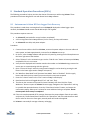
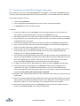
icListen Operations Guide August 27, 2013 icListen Smart Hydrophones Ocean Sonics Ltd. Hill House, 11 Lornevale Road, Great Village, NS, B0M 1L0 Canada Phone: +1 902 655 3000 www.OceanSonics.com Table of Contents Table of Contents ........................................................................................................................................... i Table of Figures ............................................................................................................................................ iv 1 Overview ............................................................................................................................................... 1 2 Features of icListen ............................................................................................................................... 2 3 4 2.1 LF – Low Frequency ....................................................................................................................... 2 2.2 LF – Feature Summary .................................................................................................................. 3 2.3 HF – High Frequency ..................................................................................................................... 4 2.4 HF – Feature Summary.................................................................................................................. 5 Quick Start – Bench Setup..................................................................................................................... 6 3.1 Checklist ........................................................................................................................................ 6 3.2 Steps .............................................................................................................................................. 6 Using the LucyTM Software .................................................................................................................... 9 4.1 5 Processing in icListen .......................................................................................................................... 10 5.1 Waveform (Time Domain) Data .................................................................................................. 10 5.1.1 Real-Time Data .................................................................................................................... 10 5.1.2 Stored WAV Data ................................................................................................................ 10 5.1.3 Gain ..................................................................................................................................... 11 5.2 6 Overview ....................................................................................................................................... 9 Power Spectrum (FFT) Data ........................................................................................................ 12 5.2.1 Real-time Data .................................................................................................................... 12 5.2.2 Stored FFT Data ................................................................................................................... 12 5.2.3 Windowing .......................................................................................................................... 12 5.2.4 FFT Processing Options ....................................................................................................... 13 5.3 Epoch Mode ................................................................................................................................ 15 5.4 Start Time and Duty Cycling ........................................................................................................ 16 Additional Features of icListen............................................................................................................ 17 6.1 Temperature and Humidity ........................................................................................................ 17 icListen Operations Guide © August, 2013 i 7 8 9 6.2 Battery Monitoring ..................................................................................................................... 17 6.3 Buzzer Patterns ........................................................................................................................... 18 6.4 Time Synchronization.................................................................................................................. 18 6.5 Network Discovery ...................................................................................................................... 18 6.5.1 UPnP (Universal Plug and Play) ........................................................................................... 18 6.5.2 Marco/Polo ......................................................................................................................... 19 Logged Data Retrieval ......................................................................................................................... 20 7.1 icListen LF Data Retrieval ............................................................................................................ 20 7.2 icListen HF Data Retrieval ........................................................................................................... 20 Standard Operation Procedures (SOPs) .............................................................................................. 21 8.1 Autonomous icListen HF Data Logger Data Recovery................................................................. 21 8.2 Autonomous icListen HF Data Logger Deployment .................................................................... 22 Care and Maintenance ........................................................................................................................ 23 9.1 Firmware Updates....................................................................................................................... 23 9.2 File System Care .......................................................................................................................... 24 9.3 Retrieval and Storage .................................................................................................................. 24 9.4 Connector Care ........................................................................................................................... 25 9.5 Deployment................................................................................................................................. 25 9.6 Long Term Deployment .............................................................................................................. 25 10 Troubleshooting icListen ..................................................................................................................... 26 10.1 Instrument not communicating .................................................................................................. 26 10.2 I need to find out the icListen firmware version and serial number .......................................... 26 10.3 The information displayed on the web interface is blank or not updating ................................ 26 10.4 I’m starting to miss data in my icListen HF WAV logs ................................................................. 26 10.5 I can’t connect to my Ethernet icListen’s IP address .................................................................. 27 11 Functional Block Diagram ................................................................................................................... 28 12 Instrument Performance..................................................................................................................... 29 12.1 Response at 4000 Samples/sec ................................................................................................... 30 12.2 Response at 250 Samples/sec ..................................................................................................... 31 13 Options and Configurations ................................................................................................................ 32 icListen Operations Guide © August, 2013 ii 14 Wiring Tables for icListen .................................................................................................................... 33 14.1 icListen LF USB Interface ............................................................................................................. 33 14.2 icListen HF Ethernet Interface..................................................................................................... 33 14.3 icListen LF USB Cable................................................................................................................... 34 14.4 USB cable to icListen LF w/battery and sync .............................................................................. 35 14.5 icListen LF Ethernet Interface ..................................................................................................... 36 14.6 Ethernet Cable ............................................................................................................................ 37 14.7 icListen LF Shorting Jumper ........................................................................................................ 38 14.8 icListen HF Shorting Jumper ........................................................................................................ 39 15 Recommended Connectors................................................................................................................. 40 icListen Operations Guide © August, 2013 iii Table of Figures Figure 1-1: icListen Family............................................................................................................................. 1 Figure 2-1: icListen LF.................................................................................................................................... 2 Figure 2-2: icListen LF.................................................................................................................................... 3 Figure 2-3: icListen HF ................................................................................................................................... 4 Figure 2-4: icListen HF ................................................................................................................................... 5 Figure 3-1: Lucy USB/RS232 connection display ........................................................................................... 6 Figure 3-2: Lucy Ethernet connection display ............................................................................................... 7 Figure 3-3 : Lucy status display ..................................................................................................................... 7 Figure 3-4: Lucy example display .................................................................................................................. 8 Figure 4-1: Lucy main display ........................................................................................................................ 9 Figure 5-1: FFT’s with 0% Overlap............................................................................................................... 13 Figure 5-2: FFT’s with 50% Overlap............................................................................................................. 13 Figure 5-3: FFT’s with 75% Overlap............................................................................................................. 13 Figure 5-4: Epoch Triggers .......................................................................................................................... 15 Figure 10-1: Lucy status bar ........................................................................................................................ 26 Figure 11-1: Functional block diagram........................................................................................................ 28 Figure 12-1: Noise response at 4 kHz sample rate...................................................................................... 30 Figure 12-2: Noise response at 250 Hz sample rate ................................................................................... 31 Figure 14-1: Subconn MCBH8M male face ................................................................................................. 33 Figure 14-2: Subconn MCBH8M male face ................................................................................................. 33 Figure 14-3: Subconn MCIL8F female face ................................................................................................. 34 Figure 14-4: USB pin positions .................................................................................................................... 34 Figure 14-5: Subconn MCIL8F female face ................................................................................................. 35 Figure 14-6: USB pin positions .................................................................................................................... 35 Figure 14-7: Charger connector .................................................................................................................. 35 Figure 14-8: Sync wires ............................................................................................................................... 35 Figure 14-9: Subconn MCBH8M male face ................................................................................................. 36 Figure 14-10: Subconn MCIL8F female face ............................................................................................... 37 Figure 14-11: RJ-45 Pin positions ................................................................................................................ 37 Figure 14-12: Subconn MCDC8F female face.............................................................................................. 38 Figure 14-13: Subconn MCDC8F female face.............................................................................................. 39 Figure 15-1: Subconn MCBH8M male face ................................................................................................. 40 icListen Operations Guide © August, 2013 iv 1 Overview This guide covers the use, care, troubleshooting and wiring of the icListen Smart Hydrophone. The concept of the icListen Smart Hydrophone has been in development since 2005. Smart Hydrophones take the work out of gathering acoustic data in the ocean. They supply data in real units, processing it as needed before it is stored or sent to the operator. These hydrophones are ideal for a range of passive acoustic applications, such as Environmental assessments of underwater acoustic noise Monitoring for marine life, including sea mammals and spawning fish Laboratory reference hydrophone Locating sound sources, such as malfunctioning equipment, or flight data recorders Locating leaks in underwater pipes, and identifying machine noises Users communicate with icListen Smart Hydrophones through a PC program called Lucy. This program lets users view instrument data in real-time, retrieve and play stored data, and perform housekeeping functions, such as check status & configuration. Figure 1-1: icListen Family We hope you enjoy your experience with your icListen product, and look forward to receiving feedback on your experience using it. icListen Operations Guide © August, 2013 1 2 Features of icListen 2.1 LF – Low Frequency The icListen LF combines high signal integrity, high storage capacity, low power and small size with the ability to process sound data in real-time. The icListen LF can be used in a tethered mode, or as an acoustic data logger. In tethered mode, real-time waveform or spectral data can be continuously acquired by a PC running the Lucy program. As a data logger, the Smart Hydrophone can be configured using Lucy, then left for extended periods under water to collect waveform or spectral data, storing it internally. The amount of recording time is dependent upon the sample rate, as seen in the following table. Figure 2-1: icListen LF How Sample Rate Affects Storage Time Sample Rate MB per day Days with 32 GB 250 S/sec 65 492 (16 months) 500 S/sec 130 246 (8 months) 1000 S/sec 259 123 (4 months) 2000 S/sec 518 61 (2 months) 4000 S/sec 1037 30 (1 month) Note that storage time can be increased significantly by using event detection to record data periodically, or when certain conditions are detected. Waveform data is logged in the standard “.wav” format, making it accessible from a wide range of software programs. Spectral data is in .FFT format, detailed in the icListen Log File Formats document. The Lucy program is ideal for viewing stored waveform or spectral data. Spectral analysis of data is optionally performed in the instrument, and can be averaged to reduce the quantity of data transferred or stored. icListen Operations Guide © August, 2013 2 2.2 LF – Feature Summary Frequency Range: LF, 1.0 to 1600 Hz, can be extended to 6400 Hz Low power, less than 100 mW. Can be battery powered Supplies real-time data when connected to a PC Event detection, up to 5 bandwidth configurable triggers Stores up to 32GB in autonomous mode Can process data in real time. Data Format: Waveform in .WAV format. Processed in .FFT format (detailed in the icListen Log File Formats document). Monitors internal temperature and humidity Seconds can be aligned to falling edge of PPS Maximum depth: 3500 meters Interfaces - RS232/RS485, USB or Ethernet Flexible power input requirement for Ethernet and RS232/RS485: 12 - 24 VDC. o USB requires: 5 VDC. Small size, 42 mm dia. by 250 mm long (1.65” by 9.8”) Figure 2-2: icListen LF icListen Operations Guide © August, 2013 3 2.3 HF – High Frequency The icListen HF is the newest Smart Hydrophone. It combines high signal integrity, data storage capacity, low power and small size with the ability to process sound data in real-time. The icListen HF can be used in a tethered mode, or as an acoustic data logger. In tethered mode real-time waveform or spectral data can be continuously streamed to a host PC running the Lucy program. As a data logger, the Smart Hydrophone can be configured using Lucy, then left for extended periods under water to collect waveform or spectral data, storing it internally. Figure 2-3: icListen HF The amount of recording time is dependent upon the sample rate, as seen in the following table. Sample Rate 16 kS/sec 32 kS/sec 64 kS/sec 128 kS/sec 256 kS/sec 512 kS/sec How Sample Rate Affects Storage Time 24 Bit Data 16 Bit Data GB per day Days with 32 GB GB per day Days with 32 GB 4.1 7.6 2.8 11.5 8.3 3.8 5.5 5.7 16.6 1.9 11.1 2.8 33.2 0.9 22.1 1.4 66.4 0.4 44.2 0.7 88.5 0.3 *icListen HF can also log 1, 2, 4 and 8 kS/sec data *icListen HF will not currently log 24 bit data at 512 kS/sec Note that storage time can be increased significantly by enabling Duty Cycle Logging to record data periodically, or by storing processed FFT data. Waveform data is logged in the standard “.wav” format, making it accessible from a wide range of software programs. Spectral data is in .txt format, suitable for spreadsheet viewing. It is detailed in the icListen Log File Formats document. The Lucy program is ideal for viewing stored waveform or spectral data. Spectral analysis of data is optionally performed in the instrument, and can be averaged for up to one minute to reduce the quantity of data transferred or stored. icListen Operations Guide © August, 2013 4 2.4 HF – Feature Summary Frequency Range: HF, 10 Hz - 200 kHz Low power, approximately 2 W. Power input requirement, 24 VDC +/-15%. Supplies real-time waveform and processed data, in tethered mode Processed data in spreadsheet .TXT format Waveform data in WAV format, with meta data stored in file header Monitors internal temperature and humidity Monitors battery charge state (as of hardware rev 2) Indicates startup/shutdown through buzzer patterns (as of hardware rev 2) Seconds can be aligned to falling edge of PPS (as of hardware rev 2) Maximum depth: 3500 meters Size: 45 mm dia., 230 mm long (excluding connector). Depth rating: 200 or 3500 meters Figure 2-4: icListen HF icListen Operations Guide © August, 2013 5 3 Quick Start – Bench Setup It is important to test the Smart Hydrophone when it is first unpacked, and before each deployment for best results. The hydrophone works in air well enough to provide a good functional test. Arrange a work surface large enough to hold the hydrophone, cables and the PC used to run the Lucy software. 3.1 Checklist 1. Hydrophone to be tested (note its serial number). 2. A PC (ideally the same portable one used to deploy the hydrophone), with the Lucy software previously installed. Ensure the PC has a suitable data port interface for the icListen instrument. 3.2 Steps 1. Start up the Lucy program on the PC. 2. Connect the icListen to the link cable, and the data link to the PC. 3. Click the Link Setup button in the lower right. In the popup window, select the appropriate connection type. To find your icListen, click “Find All Units”. To connect double click the unit from the found unit list. Figure 3-1: Lucy USB/RS232 connection display icListen Operations Guide © August, 2013 6 Figure 3-2: Lucy Ethernet connection display 4. Click the ‘Enquire’ button in the middle top of the display. A message to the right will display in black if enquire is successful, or red otherwise. Note the serial number in the displayed message to ensure it matches the number on the hydrophone. The message also displays the sensor temperature (which may be slightly different from that outside the instrument), and the internal humidity. Figure 3-3 : Lucy status display 5. The humidity is an indication of the seal quality. A humidity reading of 50% or less is acceptable. Higher readings indicate a possible leak in the seal. Contact Ocean Sonics if the humidity is higher than 80%. Close the Setup window if it is still open. 6. Click the ‘Start’ button in the top left corner. The display should begin to show data in the charts. Gently tap the hydrophone, or whistle near it, to cause a change in the display. If the display is black/red, change the reference setting on the bottom left until blue or green is visible. 7. If a changing data display is seen, the hydrophone is ready to put in the water. Events will show up on the display approximately 1 second after they have occurred. See the following display for an example. icListen Operations Guide © August, 2013 7 Figure 3-4: Lucy example display *Note that if the Enquire button returns a red message, there may be a link problem. Check that connections to the hydrophone and PC are correct. If the instrument requires external power (RS-232 or Ethernet) ensure power is supplied to the instrument. See the ‘Troubleshooting’ section for more if the problem persists. icListen Operations Guide © August, 2013 8 4 Using the LucyTM Software 4.1 Overview The software used to talk to the icListen hydrophones is a PC program called Lucy. It presents data to the operator in a graphical and numerical format. The interaction of the software has been designed for field operations personnel, making it simple to use once configured. Figure 4-1: Lucy main display Please refer to the Lucy User’s Guide for instructions on operating the Lucy software. icListen Operations Guide © August, 2013 9 5 Processing in icListen One thing that makes icListen hydrophones smart is their ability to process data. Several types of processing are available to icListen devices, all of which add value to the data. icListen is capable of transmitting real-time waveform data, and storing this data for later analysis as well. All icListen smart hydrophones can convert incoming data to power spectrum frequency data. This data can be processed in different ways, transmitted in real-time, stored, or used to trigger different effects in Epoch mode. In icListen HF, waveform data can either be streamed or logged. Spectrum data can be collected through command and control, streamed, or logged (but not streamed and logged simultaneously). 5.1 Waveform (Time Domain) Data Waveform data represents the raw signal detected by a hydrophone. Acoustic data is converted from analog to digital, where it can then be processed by icListen. 5.1.1 Real-Time Data icListen LF and icListen HF are capable of transmitting real-time waveform data to users, using software such as Lucy. Along with the digital waveform data, icListen will also transmit information on how the unit was configured when the data was collected and scaling information, which can be used to convert the received numbers to voltage or pressure measurements. 5.1.2 Stored WAV Data Waveform data may also be stored by icListen LF and icListen HF in standard uncompressed WAV files. This makes data recorded by icListen readable by many third party sound editing programs and analysis tools, as well as by Ocean Sonics’ Lucy software. In addition to the waveform data, icListen will store additional metadata in the WAV file’s LIST chunk, which can prove to be useful for analysis. For more information on the WAV file format, and the additional information provided in the LIST chunk, please refer to the icListen Log File Formats document. Data from an icListen HF can be retrieved using SCP or SFTP over port 22, using a program such as FileZilla. The username is “icListen”, and by default there is no password. Files can also be retrieved from icListen HF through “data” page of the web interface in software release 15 or newer. Files may be retrieved from icListen LF over the communications channel using Ocean Sonics’ Lucy. icListen Operations Guide © August, 2013 10 5.1.3 Gain All icListen models are capable of applying gain to the waveform data. Applying gain affects the dynamic range of the instrument, by increasing the minimum amplitude signal which can be detected by an instrument, and decreasing the maximum amplitude signal which can be measured by the instrument. This behavior makes increasing gain desirable in quiet environments where important information could be otherwise lost, but undesirable in loud environments where data would be lost due to “clipping” of the signal if gain were applied. icListen LF applies gain to waveform data in hardware, while icListen HF applies gain in software (to 16bit data only). icListen HF supplies waveform data in 16bit or 24bit formats, and makes use of gain to allow access to the low 8bits of data which would otherwise be lost when returning only 16bits. icListen Operations Guide © August, 2013 11 5.2 Power Spectrum (FFT) Data One of the most powerful processing features of icListen smart hydrophones is their ability to provide power spectrum frequency data. Looking at data in the frequency domain, rather than the time domain, provides a clearer picture of what’s going on within a sound, and can dramatically reduce the storage and bandwidth requirements of an operation. 5.2.1 Real-time Data All icListen models are capable of providing real-time FFT data. This data provides a clear picture of what’s happening in a sound. Transmitting FFT data rather than waveform data reduces the bandwidth requirement dramatically as well, which saves on transmission costs, and improves reliability. This data is also accompanied by information on how the unit was configured when the data was collected, as well as scaling information which can be used to convert the data from voltage to pressure measurements. 5.2.2 Stored FFT Data icListen LF is capable of storing processed power spectrum data in files of type .FFT. This is a binary file format, similar to the WAV file format used for waveform data. icListen HF is capable of storing processed power spectrum data in tab separated variable format TXT files. These files can be read by virtually any spreadsheet or text editor program. Storing spectrum data can provide a much more compact form of data storage than waveform data, allowing for faster data retrieval and analysis. It also reduces the storage capacity requirements, and means that the unit can store data for longer periods of time between data retrievals. In addition to the spectrum data, both file formats also store additional information, such as temperature and humidity, which can be used to aid in analysis. For more information on the .FFT and .TXT file types, please refer to the icListen Log File Formats document. Data from an icListen HF can be retrieved using the SCP or SFTP protocols on port 22, using a program such as FileZilla. Files can also be retrieved from icListen HF through the “data” page of the web interface in release 15 or newer. The username is “icListen”, and by default there is no password. Files may be retrieved from icListen LF over the communications channel using Ocean Sonics’ Lucy. 5.2.3 Windowing icListen makes use of the Hann window function, in order to reduce spectral leakage, when converting data from time to frequency domain. icListen Operations Guide © August, 2013 12 5.2.4 FFT Processing Options Not all applications require data to be processed in the same way. For this reason icListen has been designed to allow multiple options for power spectrum data processing. 5.2.4.1 Overlap It is often useful to have some overlap in the waveform data used to compute frequency data. This helps to improve the time resolution of the resulting data. The figures below show an example waveform data set, divided into sections which are used to compute frequency data. These figures show the data used with no overlap (0%), 50% overlap, and 75% overlap. Figure 5-1: FFT’s with 0% Overlap Figure 5-2: FFT’s with 50% Overlap Figure 5-3: FFT’s with 75% Overlap An overlap can be used in combination with mean, peak value, and filtered (exponential moving average) processing. icListen HF uses a 50% overlap for all spectrum data, while icListen LF allows the overlap to be adjusted. icListen Operations Guide © August, 2013 13 5.2.4.2 Mean Average This form of processing will calculate the mean average power found at each frequency, over a configurable averaging period. The averaging period is the number of FFT data sets over which the average is calculated. The mean value for each frequency bin is calculated as follows: ∑| | Where: N = Averaging Period Yi2 = Signal Power of frequency bin Ci,j = FFT Coefficient i = Frequency Bin Number j = FFT Data Set Number 5.2.4.3 Peak Value Detect Peak value detect processing keeps track of the maximum power level found at each frequency. This can be configured to be done over a set number of FFT data sets, or configured to reset the detected peak value only when data is retrieved from the unit. For icListen HF, this must be configured as a set number of FFT data sets (reset when retrieved mode is not available). 5.2.4.4 Filtered This form of processing performs infinite impulse response (IIR) filtering on the power levels detected at each frequency. The type of filter used is an exponential moving average. The weighting of the average, as well as how frequently the icListen will transmit results are both configurable in this mode. This has the effect of smoothing new data with the previous FFT results. The filtered data for each frequency is calculated as follows: ( ) | | Where: N = Weighting Factor Yi,j2 = Signal Power of frequency bin Ci,j = FFT Coefficient i = Frequency Bin Number j = FFT Data Set Number icListen Operations Guide © August, 2013 14 5.3 Epoch Mode In Epoch mode, icListen can be configured to detect specific signals in the real-time data, and perform a number of tasks based on those signals. An icListen can check the data for 5 independent triggers as shown in the following figure. Figure 5-4: Epoch Triggers Epoch triggers consist of 3 settings. The first setting is the signal conditions required to activate the trigger. This is called the test. Secondly there is the hold, which is how long the action lasts after the triggering signal disappears. Finally there is the resulting action, which is the action icListen takes when triggered. The actions available to icListen LF are: sending a signal pulse, logging data, or preparing data to send when scanned. The actions available to icListen HF are: sending and logging trigger detail messages, and logging data. icListen HF begins logging triggered data at the top of the second at which an event was detected, while icListen LF begins sending or logging data immediately after the event is detected. Note: Different events can have different result actions. icListen Operations Guide © August, 2013 15 5.4 Start Time and Duty Cycling icListen HF can be configured to start logging data at a specific date/time. Configuring a start time allows a deployment to be set up well in advance of an actual testing/monitoring session, without unwanted data being logged during this time. Until the start time has been reached, no internal logging of either waveform (WAV files) or frequency spectrum (TXT files), will be logged, but data can still be streamed live from the instrument. When storing waveform data, icListen HF can also perform duty cycling, to reduce the amount of data logged internally. The active/idle portions of the duty cycle can be configured with 1 minute resolution, and the first active phase of logging will begin when the configured start time has been reached. icListen Operations Guide © August, 2013 16 6 Additional Features of icListen icListen also contains some additional features that can aid with troubleshooting, deployment, and operation of the device. These features include: monitoring temperature and humidity, measuring battery charge state, producing buzzer patterns to indicate power up/down of the unit, and network device discovery options for Ethernet icListen devices. 6.1 Temperature and Humidity Temperature and humidity values are continuously measured internally in all icListen models. The internal temperature of an icListen will generally be slightly warmer than the outside temperature (more so when the unit is out of water). It can be useful in determining if there have been any temperature shocks experienced during testing. Rapid changes in temperature can result in a DC offset being introduced to waveform data. In some cases the offset can be great enough to “clip”/”max out” the data. This effect is expected and temporary, and knowing the temperature changes that the device experienced can help in determining if this is occurring. The relative humidity reading can be used to determine the seal quality of the instrument. A humidity reading of 50% or lower is acceptable. If the reading is higher than this, it may indicate that there is a leak in the seal. Contact Ocean Sonics if the humidity is higher than 80%. 6.2 Battery Monitoring As of hardware release 2, icListen HF monitors the charge and state of the internal battery. The stored charge, as well as the battery voltage, current, temperature, charging state, board supply voltage, and processor supply voltage are all continuously monitored during operation. This allows a user both to know when the batteries have been fully charged, estimate how long the icListen will run from the internal battery, and can be used to indicate if there are any issues with the battery. icListen Operations Guide © August, 2013 17 6.3 Buzzer Patterns In icListen HF hardware release 2, a buzzer motor was added to indicate status of the unit. These patterns can be used to ensure that the device is functioning as expected. The patterns produced by icListen are given in the following table: Buzzer Patterns used by icListen Pattern Meaning Pattern Unit Booting Up 1 short pulse (0.5s each) Firmware is Ready/Running 2 short pulses (0.5s each) Unit Shutting Down 3 short pulses (0.5s each) Error Booting Unit 1 short & 1 long pulse (0.5s and 1s), repeated 3x *Note that the error pattern may repeat multiple times if unit is unable to boot *The “Unit shutting Down” pattern will also be played when a unit is powered on after the battery has been fully drained when using software release 19 or earlier. 6.4 Time Synchronization All icListen devices are capable of having their time of day set over the command & control connection to the device. This can be done using Ocean Sonics’ Lucy software. Data can also be synchronized to the falling edge of a pulse per second (PPS) signal, allowing synchronization between multiple units. PPS synchronization is not available on icListen HF hardware release 1. 6.5 Network Discovery In order to make finding your icListen device on a network easier, some network discovery protocols have been implemented on Ethernet units. icListen LF Ethernet models have UPnP (Universal Plug and Play enabled, while icListen HF Ethernet modules make use of Ocean Sonics Marco/Polo protocol to discover IP addresses. 6.5.1 UPnP (Universal Plug and Play) UPnP is a set of networking protocols, which allows a device to automatically be discovered by any computer which has UPnP services enabled on the same subnet as the device. UPnP is enabled by default on Windows 7 and Vista, and UPnP devices can be found under “Network”. When UPnP is enabled on Windows XP, UPnP devices can be found under “My Network Places”. UPnP is not enabled by default in Windows XP (visit support.microsoft.com for details on how to enable this feature). icListen Operations Guide © August, 2013 18 6.5.2 Marco/Polo A pair of programs (Marco and Polo), are used to discover icListen HF units on a network. Marco is the application used by the end user on a PC which scans the network for devices, while Polo exists on the icListen unit and responds to messages from Marco. Using Marco, a unit can be discovered on a local network, or through a direct connection to a device, even when not on the same subnet. Marco also allows the network settings of the icListen unit to be adjusted. A copy of the Marco software is provided on the data stick supplied with icListen HF units. As of version 3.6, Ocean Sonics’ Lucy software is also capable of finding units using the same message protocol. icListen Operations Guide © August, 2013 19 7 Logged Data Retrieval icListen LF and icListen HF can be configured to log data onto an internal storage device. This section describes how to retrieve that data from the instrument following a deployment. 7.1 icListen LF Data Retrieval Data logged in an icListen LF is retrieved using the Lucy software’s file utility. The details on how to use Lucy to retrieve logged data can be found in the Lucy User’s Manual, under the section “File Utility”. 7.2 icListen HF Data Retrieval Data logging in an icListen HF can be retrieved by two different methods. These methods are SFTP/SCP and the web interface. SFTP/SCP: The SFTP/SCP protocols may be used to retrieve data files from an icListen HF. This is typically done using a program such as “FileZilla”. The login user name is “icListen”, and by default there is no password. Port 22 is used when making SFTP/SCP connections. Web Interface (Release 15 and newer): Data can be retrieved through the icListen HF’s web interface as of release 15 (July 2012). The web interface is accessed by entering the IP address of the icListen into a standard web browser (such as Internet Explorer, Firefox, or Chrome). On the web page, click “data” and follow the instructions present on the page. icListen Operations Guide © August, 2013 20 8 Standard Operation Procedures (SOPs) The following procedures help to minimize the chance of human error while using icListen. These procedures have been designed for use with Ocean Sonics Lucy software. 8.1 Autonomous icListen HF Data Logger Data Recovery This procedure is used when retrieving data from an icListen HF deployed as a data logger. Upon retrieval, the icListen should contain stored WAV and/or TXT log data. This procedure requires access to: An icListen HF (retrieved after survey has been completed) A PC running Ocean Sonics Lucy software (v3.6 or newer), and any web browser An icListen HF test cable, and power adapter Procedure: 1. Connect the test cable to the PC and icListen, connect the power adapter to the test cable and mains power, and wait approximately 1 minute for the icListen to start up. 2. On the PC, start the Lucy software and open the Link panel by pressing the Link Setup button on the lower right area of the window. 3. Select “Ethernet” as the connection type. Use the “Find All Units” button to locate your icListen, and double click on it to connect. 4. Verify that the displayed serial number matches the number on the icListen being recovered to ensure you are communicating with the right unit. 5. Open “icListen HF Setup” tab on the setup panel in Lucy (this can be done by pressing the Job button in the lower right section of Lucy’s main panel). 6. Set ‘Waveform Data Mode” and “Spectrum Data Mode” both to “Disabled”. Click the apply button and check the Lucy status line to ensure that the setup was accepted. 7. Press the “icListen” button in the “Files” section of Lucy’s main display. 8. Download and archive all logged data (all “txt” and “wav” files). 9. The data on the instrument may now be cleared. On Lucy’s Link Panel click the “Open Webserver” button to open the icListen’s browser page. Navigate to the “Operations” tab. Log in to enable the operation buttons. Press the “Clean Data Partition” button, and accept the confirmation popup. Allow up to 5 minutes for reset and data clearing to complete. Do not remove power until startup is completed. 10. If the unit must be powered off for storage, disconnect the power adapter from the test cable, and press the “Power Down/Reset” button on the “Operations” tab of the web interface. Note that in order for the unit to start again, external power will need to be applied. 11. icListen is now ready for storage or battery recharging. icListen Operations Guide © August, 2013 21 8.2 Autonomous icListen HF Data Logger Deployment This procedure is used when deploying icListen HF as a data logger. In this setup, the icListen logs data internally, while being powered by a battery (the internal battery, or an external battery may be used). This procedure requires access to: A fully charged icListen HF A PC running Ocean Sonics Lucy software (v3.6 or newer), and any web browser An icListen HF test cable, and power adapter Procedure: 1. Connect test cable to the PC and icListen, connect the power adapter to the test cable and mains power, and wait approximately 1 minute for the icListen to start up. 2. Start Lucy and open the Link panel by pressing the Link button on the lower right of the window. 3. Select “Ethernet” as the connection type. Use the “Find All Units” button to locate your icListen, and double click on it to connect. 4. Verify that the displayed serial number matches the number on the icListen being deployed. 5. Open “icListen HF Setup” tab on the setup panel in Lucy (this can be done by pressing the Job button in the lower right section of Lucy’s main panel). 6. Synchronize the time on the icListen using the “Sync Time” button. Check Lucy’s status line to verify that the time sync has been performed (this is the line of text displayed beside the “Enquire” and “Clr” buttons on Lucy’s main panel). 7. Set all waveform settings (bandwidth, data mode, log length, and duty cycling if applicable), and spectrum settings (bandwidth, log length, data mode, and processing) as required by the survey. Also set the logging delay and epoch setups as per the survey requirements. Click the apply button and check the Lucy status line to ensure that the setup was accepted. 8. On Lucy’s Link Panel click the “Open Webserver” button to open the icListen’s browser page. 9. Ensure that previously recorded data on the icListen has been archived. Navigate to the “Operations” tab. Log in to enable the operation buttons. Press the “Clean Data Partition” button, and accept the confirmation popup. Allow up to 5 minutes for reset and data clearing to complete. Do not remove power until startup is completed. 10. Navigate to the “Settings->Data Collection” tab. Verify that all data collection settings match the survey setup. 11. If the unit must be powered off before deployment, disconnect the power adapter from the test cable, and press the “Power Down/Reset” button on the “Operations” tab of the web interface. Note that in order for the unit to start again, external power will need to be applied. 12. Disconnect the test cable from the PC and icListen, and connect the dummy plug or external battery to the icListen. icListen is now ready for deployment. icListen Operations Guide © August, 2013 22 9 Care and Maintenance To get the best performance and longest service life possible out of your icListen, it is important to properly care for and maintain your unit. Here are a few things which should be remembered when using your icListen. 9.1 Firmware Updates Occasionally, Ocean Sonics may provide firmware updates for icListen. The firmware for icListen LF is updated over the command and control communications channel, and can be done using Ocean Sonics’ Lucy. For more detail on this update procedure, please refer to the Lucy User’s Guide. Updates for icListen HF are applied using the SCP or SFTP protocols. WARNING: Applying firmware updates to icListen HF will cause all logged WAV and TXT data to be erased from the instrument. Programs such as FileZilla may be used for this. The update file will be named icListenUpdate###.icu (with ### replaced by the release number of the update), and may be applied using the following steps: 1. Power the icListen using the power adapter (do not power from battery). 2. Connect to the icListen via SFTP or SCP on port 22. The login is "icListen", and there is no password. 3. Once connected, you should see a directory called "update". If this directory does not exist, create it. This directory name is case sensitive. 4. Upload the update ".icu" file into the "update" directory. 5. Disconnect from the icListen SFTP/SCP connection. 6. Connect to the icListen via a web browser, by entering its IP address into the address bar. 7. Once on the web page, go to the "Settings" page. 8. Click the "Power Down/Reset" button, and confirm that you want to reboot. 9. Allow approximately 5 minutes for the update to complete. 10. Reconnect to the icListen via your web browser, and check that the “Release” number indicated on the home page matches the provided update. You may need to hold Ctrl and press F5 to ensure that the information displayed is not old information from your browser’s cache (the refresh button on the browser generally does not guarantee this). icListen Operations Guide © August, 2013 23 9.2 File System Care To maintain optimal performance, Ocean Sonics recommends that logging be disabled, and all files be cleared from the system when the instrument is not in use. This will prevent accidentally deploying an instrument that has no storage capacity remaining. For icListen LF, files can be cleared by deleting them using the file utility provided by Lucy. icListen HF is capable of storing data collected at much higher sample rates than icListen LF, so an additional “Clean Data Partition” function has been implemented in order to maintain optimal logging performance. The cleaning function can be accessed via the web interface. This function deletes all logged files, and formats the data logging partition for optimal performance. Ocean Sonics recommends using the “Clean Data” function before any major deployments where logging is to be used. 9.3 Retrieval and Storage When your icListen is being retrieved, it is important to rinse off the unit with fresh water. This will avoid corrosion and keep salt crystals from forming on the connectors. Failure to do this could result in the need to have the instrument serviced, to replace the connectors. For icListen LF, if your unit is battery powered by using a shorting plug, ensure the shorting plug has been disconnected from the unit after retrieval. For icListen HF, make sure your unit is powered down by disconnecting the power adapter from the test cable, and press the “Power Down/Reset” button on the “settings” tab of the web interface. icListen HF may also be powered down by fully inserting, then removing, the Power Down plug included with the unit. These steps will avoid running down the battery, or possibly logging data while in storage. Failure to do this will not damage the unit but could result in lost time while the battery is being recharged, or while clearing or retrieving unnecessary log files from the unit. icListen Operations Guide © August, 2013 24 9.4 Connector Care Ensure that the mating surfaces of the connector are fully seated before deploying the instrument. Failure to do this could result in shorted connections when the unit is placed in the water. Never use excessive force to seat connectors. This may result in the pins being broken or bent, which could result in down time while the connectors are being replaced. If a connector is tough to get in place, lubricate the rubber parts of the connector sparingly using Molykote 44 Medium lubricant. Never use the backshell/fastening nut to force the connector into place. This could result in damage to the connector or backshell, and may result in the connectors not being fully seated in place. The connector should not be exposed to extended periods of heat or sunshine. Should this occur and the connectors become very dry, they should be soaked in fresh water before use. Any accumulation of sand or mud in the female contact should be removed with fresh water. Failure to do so could result in the splaying of the female contact and damage to the O-ring seals. Disconnect by pulling straight, not at an angle. Do not pull on the cable, and avoid sharp bends at cable entry. 9.5 Deployment When deploying an icListen, it is a good idea to apply some gentle soap, such as dishwashing liquid, to the surface of the hydrophone. This will help to break the surface tension, avoiding bubbles forming on the hydrophone surface, which could have adverse effects on the signal quality. If your icListen will be internally logging data, make sure that the file system is ready (see File System Care). 9.6 Long Term Deployment For long term deployments, contact Ocean Sonics for support. icListen Operations Guide © August, 2013 25 10 Troubleshooting icListen 10.1 Instrument not communicating Check wiring. If externally powered, ensure power is functional using a multimeter. Re-seat plugs and connectors. Check data link interface on PC with another device to ensure PC interface is working. If using RS-232 option, ensure the baud rate is correct, or use the auto-detect option in Lucy. If the cable was recently wired up or modified, ensure that the TX and RX lines are not reversed. 10.2 I need to find out the icListen firmware version and serial number The instrument’s serial number is printed on the side of instrument, and its carrying case. The firmware version and serial number can be retrieved by sending an Enquire command to icListen. This can be done in Lucy by clicking the ‘Enquire’ button and noting the response to the button’s right, or by connecting to the unit using the “Link” panel. Figure 10-1: Lucy status bar The firmware version and serial number are also available through the “Home” or “About” sections of the web interface. 10.3 The information displayed on the web interface is blank or not updating Your web browser may be displaying the page from a cached version. For most browsers, holding Ctrl while pressing F5 will force all files in the cache to be discarded, and refresh the page (this is often not done when using the refresh button, or pressing F5 without holding Ctrl). If this fails you may need to manually clear all browser cache to remedy the issue (Ctrl + Shift + Delete on most browsers). 10.4 I’m starting to miss data in my icListen HF WAV logs If network usage on the instrument is heavy (can be caused by streaming/scanning data in Lucy, or activity on the web interface or SSH port), small amounts of data loss may occur. Reducing the network usage when possible during internal logging operations is advised to avoid this. Over time, as files are logged and deleted on any file system, the efficiency of writing to that file system may decrease. The efficiency can be recovered by proper formatting of that file system. Use the “Clean Data Partition” button, on the icListen HF web server to format the data logging partition for optimal performance. WARNING: Make sure all logged data is backed up from icListen before performing this action, as it erases all logged data on the instrument. icListen Operations Guide © August, 2013 26 10.5 I can’t connect to my Ethernet icListen’s IP address Do not add leading 0’s to any part of the IP address. Many applications will treat address fields with leading 0’s as base 8 numbers instead of base 10. For example, if your address is 10.11.12.1, and you type 010.011.012.001 into your browser or Lucy, you will not be able to connect to the instrument (010.011.012.001 will be interpreted as 8.9.10.1). If this fails to fix the problem, make sure that your computer is on the same network as your icListen. If your icListen and computer are on separate private networks, it will not be possible to connect to it. For icListen HF, either Ocean Sonics’ Marco or Lucy v3.6 or newer can be used to reconfigure the device’s network settings to make the instrument accessible. For icListen LF, your computer network settings must be adjusted in order to allow it to communicate with icListen. icListen Operations Guide © August, 2013 27 11 Functional Block Diagram The drawing below shows the icListen LF key functions. The Blocks on the left of the diagram represent connector functions. Not all interface functions are available on all instruments. Figure 11-1: Functional block diagram icListen Operations Guide © August, 2013 28 12 Instrument Performance The charts on the following pages show the frequency and noise response of the icListen LF instrument at the 250Hz and 4000Hz sample rates. The first chart shows a conventional voltage and ADC count response versus frequency, over the bandwidth of the instrument. The second chart shows the instrument dynamic range, as a function of the maximum signal and the measurement noise floor. icListen Operations Guide © August, 2013 29 12.1 Response at 4000 Samples/sec The following charts show the icListen LF performance, for its default sample rate of 4000 Samples/sec. Note that the bandwidth at this sample rate is 1600 Hz. Figure 12-1: Noise response at 4 kHz sample rate icListen Operations Guide © August, 2013 30 12.2 Response at 250 Samples/sec The following charts show the icListen LF performance for its default sample rate of 250 Samples/sec. Note that the bandwidth at this sample rate is 100 Hz. Figure 12-2: Noise response at 250 Hz sample rate icListen Operations Guide © August, 2013 31 13 Options and Configurations The configuration options for icListen LF are listed in the table. Spec Standard Options Depth 200 meters 3500 meters Connection Male 8-pin bulkhead - Frequency 1.0 Hz - 1600 Hz - Use Tethered / Mooring with battery Autonomous with internal battery The configuration options for icListen HF are listed in the table. Spec Standard Options Depth 200 meters 3500 meters Connection Male 8-pin bulkhead Male 10-pin bulkhead Interface Ethernet 100 base-T - Frequency 10 Hz - 200 kHz - Use Tethered / Mooring with battery / Autonomous with internal battery - icListen Operations Guide © August, 2013 32 14 Wiring Tables for icListen The following are standard pinouts used with molded cables and shorting jumpers provided by Ocean Sonics. As your application may have specific requirements, please refer to the wiring table provided with your unit. Drawings of the molded cables are available by request from Ocean Sonics. 14.1 icListen LF USB Interface Subconn MCBH8M 1 2 3 4 5 6 7 8 Signal Name GND VBATVCC VBAT+ DM DP SYNCSYNC+ Figure 14-1: Subconn MCBH8M male face 14.2 icListen HF Ethernet Interface Subconn MCBH8M 1 2 3 4 5 6 7 8 Signal Name DCCOM TXTX+ RXRX+ DC+ SYNC+ Figure 14-2: Subconn MCBH8M male face icListen Operations Guide © August, 2013 33 14.3 icListen LF USB Cable Subconn Signal MCIL8F Name 1 2 3 4 5 6 7 8 GND VBATVCC VBAT+ DM DP SYNCSYNC+ USB Cable Wire USB Pin Colour # BLK 4 RED 1 WHT 2 GRN 3 - Figure 14-3: Subconn MCIL8F female face icListen Operations Guide Figure 14-4: USB pin positions © August, 2013 34 14.4 USB cable to icListen LF w/battery and sync Subconn Signal Whip MCIL8F Name Colour 1 2 3 4 5 6 7 8 GND VBATVCC VBAT+ DM DP SYNCSYNC+ RED/BLK BRN/WHT BRN RED BLU BLU/WHT YEL/BLK YEL USB Wire Colour BLK RED WHT GRN - USB Pin # 4 1 2 3 - Charger Splice Pin Colour BLK/WHT TIP BLK RING - Sync Pigtail Colour ORG YEL Figure 14-5: Subconn MCIL8F female face Figure 14-6: USB pin positions Figure 14-7: Charger connector Figure 14-8: Sync wires icListen Operations Guide © August, 2013 35 14.5 icListen LF Ethernet Interface Subconn MCBH8M 1 2 3 4 5 6 7 Signal Name DCCOM TXTX+ RXRX+ DC+ 8 N/C Figure 14-9: Subconn MCBH8M male face icListen Operations Guide © August, 2013 36 14.6 Ethernet Cable Subconn MCIL8F 1 2 3 4 5 6 7 8 Signal Name DCCOM TXTX+ RXRX+ DC+ SYNC Ethernet Wire Colour RJ-45 Pin # BRN BLU GRN 6 WHT/GRN 3 ORG 2 WHT/ORG 1 WHT/BRN WHT/BLU - Figure 14-10: Subconn MCIL8F female face icListen Operations Guide DC Power Connector RING (-) RING (-) RING (+) Figure 14-11: RJ-45 Pin positions © August, 2013 37 14.7 icListen LF Shorting Jumper To run icListen LF in battery mode, a shorting jumper is used to connect the power pins to the battery voltage. Pin # 1 2 3 4 5 6 7 8 Subconn Shorting Jumper Circuit Name Wire Colour A A B Not B Defined C C D D Figure 14-12: Subconn MCDC8F female face icListen Operations Guide © August, 2013 38 14.8 icListen HF Shorting Jumper To run icListen HF in battery mode, a shorting jumper is used to indicate that the unit is running on battery. The icListen HF shorting jumper can also be used with the icListen LF, but newer icListen HF units require the configuration below to take advantage of all power management functions. Subconn Shorting Jumper Pin # Circuit Name Wire Colour 1 A 2 A 3 B 4 B Not Defined 5 C 6 C 7 A 8 A Figure 14-13: Subconn MCDC8F female face icListen Operations Guide © August, 2013 39 15 Recommended Connectors The following table lists all the connectors used by icListen. Please ensure you check the number of pins and the connector gender before ordering connectors or whips from another vendor. All listed are rated to 3500 M depth. Connection Maker Bulkhead - Male Subconn Pins 8 Part # Thread MCBH8M Mate & Backshell Dummy/Short Plug MCIL8F & MCDLSF MCDC8F Figure 15-1: Subconn MCBH8M male face icListen Operations Guide © August, 2013 40