1
MPC-122-K Hardware
User’s Manual
Second Edition, June 2011
www.moxa.com/product
© 2011 Moxa Inc. All rights reserved.
MPC-122-K Hardware
User’s Manual
The software described in this manual is furnished under a license agreement and may be used only in accordance with
the terms of that agreement.
Copyright Notice
© 2011 Moxa Inc. All rights reserved.
Trademarks
The MOXA logo is a registered trademark of Moxa Inc.
All other trademarks or registered marks in this manual belong to their respective manufacturers.
Disclaimer
Information in this document is subject to change without notice and does not represent a commitment on the part of
Moxa.
Moxa provides this document as is, without warranty of any kind, either expressed or implied, including, but not limited
to, its particular purpose. Moxa reserves the right to make improvements and/or changes to this manual, or to the
products and/or the programs described in this manual, at any time.
Information provided in this manual is intended to be accurate and reliable. However, Moxa assumes no responsibility for
its use, or for any infringements on the rights of third parties that may result from its use.
This product might include unintentional technical or typographical errors. Changes are periodically made to the
information herein to correct such errors, and these changes are incorporated into new editions of the publication.
Technical Support Contact Information
www.moxa.com/support
Moxa Americas
Moxa China (Shanghai office)
Toll-free: 1-888-669-2872
Toll-free: 800-820-5036
Tel:
+1-714-528-6777
Tel:
+86-21-5258-9955
Fax:
+1-714-528-6778
Fax:
+86-21-5258-5505
Moxa Europe
Moxa Asia-Pacific
Tel:
+49-89-3 70 03 99-0
Tel:
+886-2-8919-1230
Fax:
+49-89-3 70 03 99-99
Fax:
+886-2-8919-1231
Table of Contents
1.
Introduction ...................................................................................................................................... 1-1
Overview ........................................................................................................................................... 1-2
Package Checklist ............................................................................................................................... 1-2
Product Features ................................................................................................................................ 1-2
MPC-122-K Hardware Specifications ...................................................................................................... 1-3
Hardware Block Diagram ..................................................................................................................... 1-5
2.
Hardware Introduction...................................................................................................................... 2-1
Appearance........................................................................................................................................ 2-2
Computer ................................................................................................................................... 2-2
Panel ......................................................................................................................................... 2-2
Dimensions ........................................................................................................................................ 2-3
LED Indicators .................................................................................................................................... 2-3
Real Time Clock .................................................................................................................................. 2-3
3.
Hardware Connection Description ..................................................................................................... 3-1
Installing the MPC-122-K ..................................................................................................................... 3-2
Wiring Requirements ........................................................................................................................... 3-2
Connecting the Power ......................................................................................................................... 3-3
Grounding the MPC-122-K ................................................................................................................... 3-3
Connecting Data Transmission Cables ................................................................................................... 3-4
Connecting to the Network ........................................................................................................... 3-4
Connecting to a Serial Device ....................................................................................................... 3-4
Installing a CompactFlash Card ............................................................................................................ 3-5
Connecting a PS/2 Keyboard and Mouse ................................................................................................ 3-6
Connecting to USB Devices .................................................................................................................. 3-7
Connecting to a Speaker or a Headphone .............................................................................................. 3-7
Upgrading the Memory Module ............................................................................................................. 3-8
Installing a SATA Hard Disk ............................................................................................................... 3-10
Installing the Hard Disk on the First HDD Bracket .......................................................................... 3-11
Installing the Hard Disk on the Second HDD Bracket ...................................................................... 3-13
4.
BIOS Setup........................................................................................................................................ 4-1
Entering the BIOS Setup Utility ............................................................................................................ 4-2
Modifying the BIOS Main Settings ......................................................................................................... 4-2
Basic Configuration ...................................................................................................................... 4-2
System Security .......................................................................................................................... 4-3
Advanced Settings .............................................................................................................................. 4-3
Hard Disk Boot Priority ................................................................................................................. 4-4
Advanced BIOS Features .............................................................................................................. 4-4
CPU Features .............................................................................................................................. 4-4
C1E Function ....................................................................................................................... 4-4
Quick Power On Self Test ...................................................................................................... 4-4
Summary Screen Show......................................................................................................... 4-4
Advanced Chipset Settings ........................................................................................................... 4-5
On-chip Frame Buffer Size .................................................................................................... 4-5
DVMT Mode ......................................................................................................................... 4-5
Total GFX Memory................................................................................................................ 4-5
Boot Display ........................................................................................................................ 4-5
Peripherals......................................................................................................................................... 4-6
OnChip IDE Device ...................................................................................................................... 4-6
SATA Mode ......................................................................................................................... 4-6
Legacy Mode Support ........................................................................................................... 4-6
Onboard Device .......................................................................................................................... 4-7
Onboard LAN Boot ROM ........................................................................................................ 4-7
Super I/O Device......................................................................................................................... 4-7
Debug Port.......................................................................................................................... 4-7
Power on After Power Fail ..................................................................................................... 4-7
Power................................................................................................................................................ 4-8
Wake Up Control ................................................................................................................................ 4-8
Hardware Monitor ............................................................................................................................... 4-8
Load Defaults ..................................................................................................................................... 4-9
Exiting the BIOS Setup ...................................................................................................................... 4-10
Upgrading the BIOS .......................................................................................................................... 4-10
A.
Regulatory Approval Statement ........................................................................................................ A-1
B.
On Screen Display Configuration ....................................................................................................... B-1
Opening the Configuration Screen......................................................................................................... B-2
Main Menu ......................................................................................................................................... B-2
Brightness .................................................................................................................................. B-2
Back Light .................................................................................................................................. B-3
Color Temperature ...................................................................................................................... B-3
Language ................................................................................................................................... B-3
OSD Settings .............................................................................................................................. B-3
Information ................................................................................................................................ B-4
System Power ............................................................................................................................. B-4
Reset to Default .......................................................................................................................... B-4
Exit ........................................................................................................................................... B-4
C.
ECDIS Library and API Development ................................................................................................. C-1
Installation ........................................................................................................................................ C-2
Source Tree ....................................................................................................................................... C-2
ECDIS Library .................................................................................................................................... C-2
Backlight Function ....................................................................................................................... C-2
mpc122k_set_backlight function ............................................................................................C-2
ECDIS RGB Data Structure ........................................................................................................... C-2
ECDIS RGB Functions .................................................................................................................. C-3
mxecdis_rgb_read_tables function .........................................................................................C-3
mxecdis_rgb_last_error function ............................................................................................C-3
1
1.
Introduction
The MPC-122-K marine panel computer features a 2.26 GHz Intel Core 2 Duo processor with up to 4 GB of
system memory to deliver a reliable high performance platform for marine system operations. Two
RS-232/422/485 optically-isolated serial ports and two Gigabit LAN ports provide reliable serial
communications and high speed Ethernet transmissions with network redundancy.
The panel is outfitted with a range of industrial features, such as optional optical bonding, wide view angles,
and full range dimming. The panel is designed to modularly integrate with the computer to reduce system
integration costs and reduce your time-to-market. Full support is provided for a wide range of panel resolutions
in order to meet the specific requirements of many different marine applications.
The MPC-122-K marine panel computers are compliant with many different industrial marine standards, such
as IEC 60945, DNV, and IACS-E10, to verify their resilience in maritime operations. The IP67 rated enclosure
provides additional protection against harsh marine environments.
Also available are ECDIS-approved models that offer the optimal solution for computers that meet the ECDIS
requirements.
The following topics are covered in this chapter:
Overview
Package Checklist
Product Features
MPC-122-K Hardware Specifications
Hardware Block Diagram
MPC-122-K Hardware
Introduction
Overview
The MPC-122-K computer is based on the Intel Core 2 Duo mobile processor and comes with 2 optically isolated
RS-232/422/485 serial ports, 2 Gigabit Ethernet ports, 7 USB 2.0 ports, and a CompactFlash socket, offering
high performance and versatile peripherals for marine, railway, power, and other industrial applications.
Users can easily install Windows 7 or Windows XP SP3 to provide a flexible and friendly environment for system
development and application implementation.
Package Checklist
The MPC-122-K Series includes the following model:
MPC-122X-K: Intel Core 2 Duo 2.26 GHz panel computer with 22” screen, full-dimming, tape bonding glass
MPC-122Y-K: Intel Core 2 Duo 2.26 GHz panel computer with 22” screen, full-dimming, optical bonding glass
MPC-122X-K-ECDIS: Intel Core 2 Duo 2.26 GHz panel computer with 22" screen, full-dimming, tape bonding
glass, ECDIS
MPC-122Y-K-ECDIS: Intel Core 2 Duo 2.26 GHz panel computer with 22" screen, full-dimming, optical
bonding glass, ECDIS
Each model is shipped with the following items:
NOTE
•
MPC-122-K panel computer
•
PS/2 to KB/MS Y-type cable
•
2 sets of hard drive cables and 1 set of SATA disk power cable
•
Rubber water proofing cushion
•
Hard drive ground sticker
•
Documentation & software CD
•
Quick installation guide (printed)
•
Warranty card
Please notify your sales representative if any of the above items are missing or damaged.
Product Features
The MPC-122-K panel computer has the following features:
•
22" wide viewable image size with 16:10 aspect ratio and 1680 x 1050 pixel resolution
•
High performance Intel Core 2 Duo 2.26 GHz processor, 6 MB L2 cache
•
Built-in 2 GB DDR3 memory, supporting up to 4 GB
•
Full range dimming, optical bonding (optional), and wide angle view (178 x 178)
•
Dual independent displays (VGA + DVI-D)
•
Water and dust proof IP67-rated enclosure (flush mounting)
•
2 Gigabit Ethernet ports for network redundancy
•
2 optically-isolated RS-232/422/485 serial ports
•
Onboard mini-PCIe slot for future expansions and upgrades
•
7 USB 2.0 ports for connecting peripheral devices
•
CompactFlash card socket and optional hard disk drive support for storage expansion
•
2 SATA connectors for storage expansion
•
Fanless and compact design
1-2
MPC-122-K Hardware
•
Low power consumption
•
Supports Windows 7, and Windows XP SP3
•
ECDIS-compliant models available
Introduction
MPC-122-K Hardware Specifications
Computer
CPU: Intel Core 2 Duo SP9300 2.26 GHz, 6 MB for L2 cache
OS: Windows 7, Windows XP SP3 (must be installed by the user)
System Chipset: Intel GS45 + ICH9M
BIOS: 8 Mbit Flash BIOS SPI type, ACPI function supported
FSB: 1066 MHz
System Memory: 2 GB DDR3 SDRAM onboard (supports DDR3 up to 4 GB)
Graphics Controller: Intel GS45 built-in
Video Output: DVI-D x 1, VGA x 1 (female)
Expansion Bus: Mini-PCIe onboard
USB: USB 2.0 ports x 7, type A connectors, supporting system boot up (6 ports on the computer, 1 port on the
panel)
Storage
Storage Expansion: CompactFlash socket
SATA Storage Support: (must be installed by the user)
• 2.5-inch SSD
• 2.5-inch HDD
Other Peripherals
KB/MS: 1 PS/2 interface supporting standard PS/2 keyboard and mouse through Y-type cable
Audio: Line-in and line-out interface, with 3.5 mm mini jack
Display
Panel Size: 22’’ wide viewable image size
Panel Type: MVA
Aspect Ratio: 16:10
Pixels: 1680 x 1050 (WSXGA+)
Pixel Pitch (RGB): 0.282 (H) x 0.282 (V) mm
Response Time: 8 ms (gray to gray)
Contrast Ratio: 1000:1
Light Intensity: 300 cd/mxm
Viewing Angles: 178/178
Active Display Area: 473.76 (H) x 296.1 (V) mm
Max Colors: 16.7M (8 bits/color)
Resolution:
• VGA: 640 x 480
• SVGA: 800 x 600
• XGA: 1024 x 768
• SXGA: 1280 x 1024
• WSXGA+: 1680 x 1050 (optimal setting)
Ethernet Interface
LAN: 2 auto-sensing 10/100/1000 Mbps ports (RJ45)
Magnetic Isolation Protection: 1.5 KV built-in
Serial Interface
Serial Standards: 2 RS-232/422/485 ports, software-selectable (DB9 male)
Optical Isolation Protection: 4 KV
1-3
MPC-122-K Hardware
Introduction
Serial Communication Parameters
Data Bits: 5, 6, 7, 8
Stop Bits: 1, 1.5, 2
Parity: None, Even, Odd, Space, Mark
Flow Control: RTS/CTS, XON/XOFF, ADDC® (automatic data direction control) for RS-485
Baudrate: 50 bps to 921.6 Kbps (supports non-standard baudrates; see user's manual for details)
Serial Signals
RS-232: TxD, RxD, DTR, DSR, RTS, CTS, DCD, GND
RS-422: TxD+, TxD-, RxD+, RxD-, GND
RS-485-4w: TxD+, TxD-, RxD+, RxD-, GND
RS-485-2w: Data+, Data-, GND
LEDs
System: Storage, Power
LAN: 100M/Link x 2, 1000M/Link x 2 (on connector)
Front Panel
LED: Storage, Power
OSD: 1 x OSD control
USB: 1 USB 2.0 host
Potentiometer: For brightness control
Physical Characteristics
Housing: Aluminum sheet metal
Weight: 15.1 kg
Dimensions: 124 x 560 x 420 mm (4.88 x 22.05 x 16.54 in)
Mounting: Flush mounting
Environmental Limits
Operating Temperature: -15 to 55°C (5 to 131°F)
Storage Temperature: -20 to 60°C (-4 to 140°F)
Ambient Relative Humidity: 5 to 95% (non-condensing)
Anti-Vibration:
• IEC 60945
• DNV 2.4, Class A/Class C
Power Requirements
Input Voltage: 24 VDC (18 to 36 VDC), screw-type terminal block
Power Consumption: 112 W
• 6.21 A @ 18 VDC
• 4.55 A @ 24 VDC
• 2.95 A @ 36 VDC
Standards and Certifications
Safety: UL/cUL, CCC
EMC: EN 55022 Class B, EN 55024-4-2, EN 55024-4-3, EN 55024-4-4, FCC Part 15 Subpart B Class A
Marine: IEC 60945 4th. (Pending), DNV (Pending), IACS-E10 (Pending)
Green Product: RoHS, cRoHS, WEEE
Reliability
Automatic Reboot Trigger: Built-in WDT (watchdog timer) supporting 1-255 levels for time interval system
reset, software programmable
MTBF (meantime between failures): 39,675 hrs
Warranty
Warranty Period: 1 year
Details: See www.moxa.com/warranty
1-4
MPC-122-K Hardware
Introduction
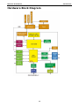
Hardware Block Diagram
1-5
2
2.
Hardware Introduction
The MPC-122-K computer is compact, well-designed, and rugged enough for marine applications. LED
indicators help you monitor performance and identify trouble spots, multiple serial ports allow you to connect
different devices for wireless operation, and the reliable and stable hardware platform lets you devote your
attention to developing your applications.
The following topics are covered in this chapter:
Appearance
Computer
Panel
Dimensions
LED Indicators
Real Time Clock
MPC-122-K Hardware
Hardware Introduction
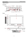
Appearance
Computer
Panel
2-2
MPC-122-K Hardware
Hardware Introduction
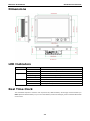
Dimensions
LED Indicators
LED Name
LED Color
LED Function
Power
Green
Power is on and functioning normally
Off
Power is off or a power error exists
Yellow (on)
CF card is inserted and detected
Yellow (blinking)
CF card or HDD is reading/writing
Off
No activity
Storage
LAN
Green
100 Mbps Ethernet mode
Yellow
1000 Mbps (Gigabit) Ethernet mode
Off
No activity or 10 Mbps Ethernet mode
Real Time Clock
The embedded computer’s real-time clock is powered by a lithium battery. We strongly recommend that you
NOT replace the lithium battery on your own. If the battery needs to be changed, please contact the Moxa RMA
service team.
2-3
MPC-122-K Hardware
Hardware Introduction
ATTENTION
There is a risk of explosion if the wrong type of battery is used. To avoid this potential danger, always be sure
to use the correct type of battery. Contact the Moxa RMA service team if you need to replace your battery.
Caution
There is a risk of explosion if the battery is replaced by an incorrect type. Dispose of used batteries according
to the instructions on the battery.
2-4
3
3.
Hardware Connection Description
In this chapter, we show how to connect the embedded computers to the network and to various devices.
The following topics are covered in this chapter:
Installing the MPC-122-K
Wiring Requirements
Connecting the Power
Grounding the MPC-122-K
Connecting Data Transmission Cables
Connecting to the Network
Connecting to a Serial Device
Installing a CompactFlash Card
Connecting a PS/2 Keyboard and Mouse
Connecting to USB Devices
Connecting to a Speaker or a Headphone
Upgrading the Memory Module
Installing a SATA Hard Disk
Installing the Hard Disk on the First HDD Bracket
Installing the Hard Disk on the Second HDD Bracket
MPC-122-K Hardware
Hardware Connection Description
Installing the MPC-122-K
Wall or Cabinet Mounting
There are a total of four screw holes on the panel, two on the left and two on the right. Use two screws per side
to attach the MPC-122-K to a wall or cabinet.
For safety reasons, it is important to ensure that the four corners and four sides of the panel are firmly attached
to the cabinet, so that the cabinet is completely stabilized.
ATTENTION
Clean the monitor using a soft material such as microfiber cloth. You may also use LCD cleaning liquid to clean
the monitor.
Avoid using coarse or rough material to clean the monitor as they may damage the optical bonding.
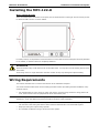
Wiring Requirements
This section describes how to connect serial devices to the embedded computer.
You should read and follow these common safety precautions before proceeding with the installation of any
electronic device:
•
Use separate paths to route wiring for power and devices. If power wiring and device wiring paths must
cross, make sure the wires are perpendicular at the intersection point.
NOTE
Do not run signal or communication wiring together with power wiring in the same wire conduit. To avoid
interference, wires with different signal characteristics should be routed separately.
•
Use the type of signal transmitted through a wire to determine which wires should be kept separate. The
rule of thumb is that wiring that shares similar electrical characteristics can be bundled together.
•
Keep input wiring and output wiring separate.
•
It is advisable to label the wiring to all devices in the system.
3-2
MPC-122-K Hardware
Hardware Connection Description
ATTENTION
Safety First!
Be sure to disconnect the power cord before installing and/or wiring your MPC-122-K.
Wiring Caution!
Calculate the maximum possible current in each power wire and common wire. Observe all electrical codes
dictating the maximum current allowable for each wire size.
If the current goes above the maximum ratings, the wiring could overheat, causing serious damage to your
equipment.
Temperature Caution!
Be careful when handling the unit. When the unit is plugged in, the internal components generate heat, and
consequently the outer casing may feel hot to the touch.
Connecting the Power
The MPC-122-K offers 18 to 36 VDC power input with the terminal block. If the power is supplied properly, the
Power LED will light up. The OS is ready when the Ready LED glows a solid green.
For safety reasons, please use cables with the following specifications:
Wire range 14-22 AWG, torque 7 lb
Grounding the MPC-122-K
Grounding and write routing help limit the effects of noise due to electromagnetic interference (EMI). Run the
ground connection from the ground screw to the grounding surface prior to connecting the power.
ATTENTION
This product is intended to be mounted to a well-grounded mounting surface, such as a metal panel.
EG: See the figure shown below for the location of the Earth Ground on the terminal block power connector.
Connect the EG wire to an appropriate grounded metal surface.
3-3
MPC-122-K Hardware
Hardware Connection Description
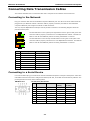
Connecting Data Transmission Cables
This section describes how to connect the MPC-122-K computer to the network and serial devices.
Connecting to the Network
Plug your network cable into the embedded computer’s Ethernet port. The other end of the cable should be
plugged into your Ethernet network. When the cable is properly connected, the LEDs on the embedded
computer’s Ethernet port will glow to indicate a valid connection.
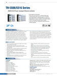
The 10/100/1000 Mbps Ethernet LAN port uses 8-pin RJ45 connectors. The following diagram shows the
pinouts for these ports.
The LED indicators on the right top and right bottom corners glow a solid green color
when the cable is properly connected to a 100 Mbps Ethernet network. The LED will
flash on and off when Ethernet packets are being transmitted or received.
The LED indicators on the left top and left bottom corners glow a solid yellow color
when the cable is properly connected to a 1000 Mbps Ethernet network. The LED will
flash on and off when Ethernet packets are being transmitted or received.
Pin
10/100 Mbps
1000 Mbps
1
ETx+
TRD(0)+
2
ETx-
TRD(0)-
3
ERx+
TRD(1)+
4
–
TRD(2)+
5
–
TRD(2)-
6
ERx-
TRD(1)-
7
–
TRD(3)+
8
–
TRD(3)-
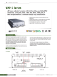
Connecting to a Serial Device
Use a serial cable to plug your serial device into the embedded computer’s serial port. Serial ports 1 and 2 have
male DB9 connectors and can be configured for RS-232, RS-422, or RS-485 communication by software. The
pin assignments are shown in the following table:
DB9 Male Port
RS-232/422/485 Pinouts
Pin
RS-232
RS-422
RS-485
(4-wire)
(2-wire)
1
DCD
TxDA(-)
TxDA(-)
–
2
RxD
TxDB(+)
TxDB(+)
–
3
TxD
RxDB(+)
RxDB(+)
DataB(+)
4
DTR
RxDA(-)
RxDA(-)
DataA(-)
5
GND
GND
GND
GND
6
DSR
–
–
–
7
RTS
–
–
–
8
CTS
–
–
–
3-4
RS-485
MPC-122-K Hardware
Hardware Connection Description
Installing a CompactFlash Card
The MPC-122-K computer comes with a CompactFlash socket. To insert a CompactFlash card, follow these
instructions:
1. Disconnect the MPC-122-K from its power source.
2. The CompactFlash socket is located on the right side of the front panel. Unscrew the CompactFlash socket
cover.
3. There is a tenon/hook on the cover of the CF socket. Turn the CompactFlash card over and then insert the
CompactFlash card into the tenon/hook of the CF socket cover.
ATTENTION
Be careful of how you orient the CompactFlash card. You should turn the CF card bottom side up, in order to
hook CF card into the CF socket cover.
4. Gently insert the CompactFlash card into the CF socket, making sure that the card is oriented correctly.
3-5
MPC-122-K Hardware
Hardware Connection Description
ATTENTION
The MPC-122-K embedded computer does not support the CompactFlash hot swap and PnP (Plug and Play)
functions. It is necessary to remove power source first before inserting or removing the CompactFlash card.
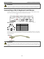
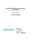
Connecting a PS/2 Keyboard and Mouse
Your MPC-122-K computer comes with a PS/2 mini-DIN connector to connect to a PS/2 keyboard and PS/2
mouse. This 6-pin mini-DIN connector has the pin assignments shown below.
PS/2 Connector
Pin No.
Signal Definition
1
PS/2 Keyboard Data
2
PS/2 Mouse Data
3
GND
4
VCC
5
PS/2 Keyboard Clock
6
PS/2 Mouse Clock
Use the Y-type cable to convert the mini-DIN connector into two 6-pin mini-DIN connectors to connect both
PS/2 keyboard and PS/2 mouse at the same time. You may also use the USB ports to connect your USB-based
keyboard and mouse.
ATTENTION
Please note that without a Y-type cable, the PS/2 connector on the MPC-122-K can only work with a PS/2
keyboard. A PS/2 mouse will not function when directly connected to the PS/2 connector on the MPC-122-K
computer.
3-6
MPC-122-K Hardware
Hardware Connection Description
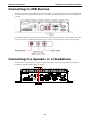
Connecting to USB Devices
The MPC-122-K comes with 6 USB 2.0 ports on the computer. The ports can be used for an external flash disk
or hard drive for storing large amounts of data. You can also use these USB ports to connect to a keyboard or
a mouse.
An additional USB port with a water-proof cover can be found on the front panel. To use, simply remove the
cover and connect to a USB supported device of your choice, such as a keyboard, mouse or storage disk.
Connecting to a Speaker or a Headphone
The MPC-122-K comes with audio input and output interfaces for connecting a microphone and speaker or
headphones. See the following figure for details.
3-7
MPC-122-K Hardware
Hardware Connection Description
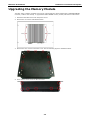
Upgrading the Memory Module
The MPC-122-K computer supports two memory sockets that have been installed with 2 GB DDR2 SDRAM
modules (1 GB for each socket). To upgrade the DDR3 SDRAM memory module, follow these instructions:
1. Disconnect the MPC-122-K from the power source.
2. Remove the six screws as illustrated below.
3. Remove the nine screws on the back cover. See the following figure for detailed location.
4. Then remove seven screws on the rear cover.
3-8
MPC-122-K Hardware
Hardware Connection Description
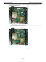
5. Remove the back cover of the computer. You will see two HDD brackets inside. The memory module is
located below the first HDD bracket.
6. Remove the four screws of the first HDD bracket. See the following figure for the specific location of the
screws.
3-9
MPC-122-K Hardware
Hardware Connection Description
7. After the first HDD bracket has been removed, you can find two memory modules. Carefully remove the
module by clicking the clutches at both sides of the module, and then replace the new module. Be sure to
orient the module correctly.
8. When finished, replace the first HDD bracket and the back cover of the computer.
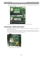
Installing a SATA Hard Disk
The MPC-122-K has two SATA connectors for installing two SATA hard disks. To install the 2.5-inch SATA hard
disks, follow these instructions.
After removing the back cover of the computer, find the HDD brackets in the following figure. Please note that
you can install your hard disk onto either HDD bracket. However, if you would like to install an SSD type disk,
we suggest you have it installed on the second HDD bracket.
3-10
MPC-122-K Hardware
Hardware Connection Description
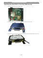
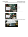
Installing the Hard Disk on the First HDD Bracket
1. Remove the four screws on the first HDD bracket.
2. Remove two black screws on each side of the bracket, and then take off the cover.
3. Place the hard disk on the bracket. Use the four screws to fasten the hard disk at both sides of the bracket.
3-11
MPC-122-K Hardware
Hardware Connection Description
4. When finished, place the bracket on the computer, and use four screws to fasten the bracket. Next, find the
location of the power connect and the SATA connectors. There is one power connector which can be used by
two SATA hard disks, and there are two SATA connectors for connecting two SATA disks.
5. Connect the power cable to the power connector and the SATA cable to the SATA connector.
6. When finished, use the ground sticker to attach the hard drive disk and the bracket. Make sure that the
metal parts of the hard drive disk and the bracket have been attached. If you are using a solid state drive
(SSD), you don’t need to attach this sticker.
3-12
MPC-122-K Hardware
Hardware Connection Description
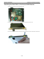
Installing the Hard Disk on the Second HDD Bracket
1. Remove the four screws on the second HDD bracket.
2. Remove two black screws on each side of the bracket, and then take off the cover.
3. Place the hard disk on the bracket. Use the four screws to fasten the hard disk at both sides of the bracket.
3-13
MPC-122-K Hardware
Hardware Connection Description
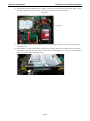
4. When finished, place the bracket on the computer, and use four screws to fasten the bracket. Next, connect
the SATA cable to the SATA connector, and the power cable to the power connector.
5. When you finish installing two hard disks on the computer, replace the back cover of the computer, and
fasten the screws.
6. When finished, use the ground sticker to attach the hard drive disk and the bracket. Make sure that the
metal parts of the hard drive disk and the bracket have been attached. If you are using a solid state drive
(SSD), you don’t need to attach this sticker.
3-14
4
4.
BIOS Setup
This chapter describes the BIOS settings of the MPC-122-K computer. The BIOS is a set of input/output control
routines for peripherals. The BIOS is used to initialize basic peripherals and helps boot the operating system
before the operating system is loaded. The BIOS setup allows the user to modify the system configurations of
these basic input/output peripherals. All of the configurations will be stored in the battery backed up CMOS
RAM, which retains the system information after system reboots or the power is removed.
The following topics are covered in this chapter:
Entering the BIOS Setup Utility
Modifying the BIOS Main Settings
Basic Configuration
System Security
Advanced Settings
Hard Disk Boot Priority
Advanced BIOS Features
CPU Features
Advanced Chipset Settings
Peripherals
OnChip IDE Device
Onboard Device
Super I/O Device
Power
Wake Up Control
Hardware Monitor
Load Defaults
Exiting the BIOS Setup
Upgrading the BIOS
MPC-122-K Hardware
BIOS Setup
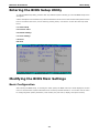
Entering the BIOS Setup Utility
To enter the BIOS setup utility, press the “Del” key while the system is booting up. The main BIOS Setup screen
will appear.
A basic description of each function key is listed at the bottom of the screen. Refer to these descriptions to learn
how to scroll about the screen, how to select by pressing “Enter,” and how to use the other hot keys listed
below.
F1: General Help
F5: Previous Value
F6: Default Settings
F7: Turbo Settings
F10: Save
ESC: Exit
Modifying the BIOS Main Settings
Basic Configuration
After entering the BIOS Setup, or choosing the “Main” option, the BIOS main menu will be displayed. Use this
menu to check the basic system information such as memory and IDE hard drive. You can also use the menu
for configuring basic system parameters, such as date, time, hard drive, display, and system security.
4-2
MPC-122-K Hardware
BIOS Setup
System Security
To set up system security, select the “Security” option under “Main” to bring up the following screen.
This menu includes two options: “Set Password” and “Security Option.”
When you select the Set Password option, a pop-up “Enter Password:” window will appear on the screen. The
password that you type will replace the password stored in the CMOS memory. You will be required to confirm
the new password. Just re-type the password and then press <Enter>. You may also press <Enter> to abort
the selection and not enter a password.
To clear an existing password, just press <Enter> when you are prompted to enter the password. A message
will show up confirming that the password will be disabled. Once the password is disabled, the system will boot
and you can enter the “BIOS Setup Menu” without entering a password.
Once a password has been set, you will be prompted to enter the password each time you enter Setup. This
prevents unauthorized persons from changing any part of your system configuration. In addition, when a
password setting is enabled, you can set up the BIOS to request a password each time the system is booted up.
The “Security Option” setting determines when a password prompt is required. If the “Security Option” is set
to “System,” the password must be entered both at boot up and when entering the BIOS Setup Menu. If the
password is set for “Setup,” the password prompt only occurs when you enter the “BIOS Setup Menu.”
Advanced Settings
The “Advanced Features” screen will appear when choosing the “Advanced” item from the main menu.
4-3
MPC-122-K Hardware
BIOS Setup
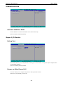
Hard Disk Boot Priority
First/Second/Third Boot Device
This option allows users to select or change the device boot priority. You may set 3 levels of priority to
determine the boot up sequence for different bootable devices, such as a hard drive, CD-ROM, and removable
devices. Select the order in which devices will be searched in order to find a boot device. The available options
are “CDROM (default for first boot device),” “Removable” (default for third boot device), “Hard Disk” (default
for second boot device) and “Disabled.”
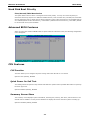
Advanced BIOS Features
When you select the “Advanced BIOS Features” option under the “Advanced” menu, the following configuration
menu will appear.
CPU Features
C1E Function
This item allows you to configure the power-saving mode when the CPU is in C1 status.
Options: Auto (default), Disabled
Quick Power On Self Test
This setting allows the system to skip certain tests while the system boots up. Enable this feature to speed up
the boot up process.
Options: Enabled (default), Disabled
Summary Screen Show
The summary screen displays system information, including CPU, memory, disk drive, and PCI devices. The
default value is disabled. You may choose “Enabled” to display this screen when the system is booting up.
Options: Disabled (default), Enabled
4-4
MPC-122-K Hardware
BIOS Setup
Advanced Chipset Settings
On-chip Frame Buffer Size
This item determines the frame buffer size for the VGA function, and will share the system memory.
Options: 32MB, 64MB (default), 128MB
DVMT Mode
When the Dynamic Video Memory Technology (DVMT) operating mode is set to “Fixed,” the graphics driver will
reserve a fixed portion of the system memory as graphics memory. When set to “DVMT,” the graphics driver
will dynamically allocate system memory as graphics memory, according to system and graphics requirements.
When set to “BOTH,” the graphics driver will allocate a fixed amount of memory as dedicated graphics memory,
as well as allow more system memory to be dynamically allocated between the graphics processor and the
operating system.
Options: Enable (default), Disable
Total GFX Memory
The GFX sets the maximum amount of system memory that can be allocated as graphics memory.
Options: 128 MB, 256 MB (default), MAX.
Boot Display
This item allows you to choose which display interface will be shown when system is booting up. Due to the
display limitation, two displays at most can be shown when booting up. If you select the default option, VBIOS
Default", the displays that have been connected will be used as the default displays.
Options: VBIOS Default (default), CRT, EFP1, EFP2, CRT+EFP1, CRT+EFP2
4-5
MPC-122-K Hardware
BIOS Setup
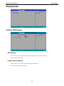
Peripherals
OnChip IDE Device
SATA Mode
This item allows you to select the IDE mode or AHCI mode for your SATA hard disk..
Options: IDE (default), AHCI
Legacy Mode Support
This item allows you to enable or disable the legacy USB device.
Options: Disabled (default), Enabled
4-6
MPC-122-K Hardware
BIOS Setup
Onboard Device
Onboard LAN Boot ROM
Decide whether to invoke the boot ROM of the onboard LAN chip.
Options: Enabled, Disabled (default)
Super I/O Device
Debug Port
This function allows you to enable/disable the debug port communication. This port is only for engineers who
are debugging program.
Options: Disabled (default), Enabled
Power on After Power Fail
This item allows you to configure the power on after power fail function.
Options: Off, On (default), Former-Sts
4-7
MPC-122-K Hardware
BIOS Setup
Power
The Power Setup Menu allows you to configure your system power-up/ power-down options.
HPET Support
This item allows you to enable/disable the HPET (High Precision Event Timer) function.
Option: Enabled (default), Disabled
HPET Mode
This item allows you to select the HPET mode.
Option: 32-bit mode (default), 64-bit mode
Soft-Off by PWR-BTTN
This item determines the delay to stop the software when pushing the power button.
Options: Instant-Off (default), Delay 4 Sec.
Wake Up Control
RTC Wake Up
This item allows you to enable/disable the RTC wake up function.
Options: Disabled (default), Enabled
Hardware Monitor
4-8
MPC-122-K Hardware
BIOS Setup
This item helps monitor the status of the system, including CPU temperature and the voltage of the CPU,
SDRAM and battery.
CPU Warning Temperature
This item allows you to configure what temperature will trigger a high temperature warning.
Options: 80°C/176°F, 90°C/194°F (default), 100°C/212°F, Disabled
Warning Beep
This item allows you to enable/disable the warning beep.
Options: Disabled (default), Enabled
Load Defaults
Load System Default Settings
Use this option to load system factory default settings instead of the current BIOS settings. This option is useful
for when the system is unstable. Users do not need to remember what settings were active before the system
fails.
Load System Turbo Settings
Use this option to load system optimized settings. If the system is not stable, please load the system default
settings.
Load CMOS from BIOS
Use this option to load BIOS settings from flash ROM to CMOS.
Save CMOS to BIOS
Use this option to save the BIOS settings from the CMOS to flash ROM.
4-9
MPC-122-K Hardware
BIOS Setup
Exiting the BIOS Setup
To exit the BIOS setup utility, choose “Exit.” Pressing <ESC> will achieve the same result.
Save & Exit Setup
Save all configuration changes to CMOS (memory) and exit setup. A confirmation message will be displayed
before proceeding.
Exit Without Saving
Abandon all changes made during the current session and exit setup. A confirmation message will be displayed
before proceeding.
Upgrading the BIOS
This section describes how to upgrade the BIOS. However, please note that upgrading the BIOS involves high
risk of damage to your computer. We strongly recommend that you contact Moxa’s TS staff for assistance and
obtain all necessary tools and files before attempting to upgrade.
Step 1: Create a Bootable USB Disk.
We suggest you use the HP USB Disk Format Tool to create a bootable USB disk. You may download this tool
from the Internet. Search the Internet using the phrase “HP USB Disk Storage Format Tool”, and then
download the tool from one of the listed websites.
You will also need to download the FreeDos system files kernel.sys and command.com from
http://www.freedos.org/kernel/.
1. Copy DOS system files kernel.sys and command.com to a specified directory (C:\FreeDOS in this
example).
2. Start the HP USB Disk Storage Format Tool and select the USB device that you want to use as a bootable
disk in the Device drop down box.
3. Select FAT in the File system drop down box.
4. Type the disk name in the Volume label field.
5. Check the option Create a DOS startup disk under format options.
6. Specify the directory of the system files (for example, C:\FreeDOS).
4-10
MPC-122-K Hardware
BIOS Setup
7. Click Start to format and create the USB disk.
ATTENTION
We suggest you use a USB drive with under 2 GB in disk space, as larger USB drives may not support FAT file
format and consequently fail to boot.
Step 2: Prepare the Upgrade Tool and BIOS Binary File.
You must use the BIOS upgrade installation file to upgrade the BIOS. You can download it from the Moxa
Download Center at:
http://web4.moxa.com/support/download_center.asp
1. Get the BIOS upgrade installation file. The file name should have following format: 451010.s02.
2. Copy the file to the Bootable USB Disk.
3. Double click to extract the BIOS update installation file. The file includes a binary file in the form
s451010.s02 and the upgrade utility named awdflash.exe.
Step 3: Set up the BIOS to Boot from the USB Disk.
1. Insert the USB disk.
2. Power on and press DEL to enter the BIOS Setup menu.
3. Select Advanced Hard Disk Boot Priority and then press Enter.
4. From the Setup menu, use “↑” or “↓” to select the USB device.
4-11
MPC-122-K Hardware
BIOS Setup
5. Press “+” to move it up to the first priority, and press “Esc” to exit the setup menu.
6. Make sure the first boot device is Hard Disk. If it isn’t, press Enter to change it.
7. Select Exit Save & Exit Setup and then press Enter.
8. Choose Y to save to the CMOS and then exit.
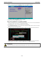
Step 4: Run awdflash.exe to upgrade the BIOS.
1. While in the BIOS Setup menu and before upgrading the BIOS, you may choose to save the old BIOS files
to a specific location. Type Y to do so, or N to begin the upgrade.
2. If the BIOS Setup is correct, it will restart and boot from the USB disk.
3. Run awdflash 451010.s02 from the command line to upgrade the BIOS. Replace xxxxxxx.Sxx with the
BIOS binary file name discussed in Step 2.
4. Press F1 to reset the system after the bios update is complete. The system should reboot at this time.
5. Please note that once the BIOS is successfully upgraded, the default BIOS values will be automatically
loaded. However, if you wish to re-configure the BIOS settings, press DEL while booting.
ATTENTION
Do NOT switch off the power supply during the BIOS upgrade, since doing so may cause the system to crash.
4-12
A
A.
Regulatory Approval Statement
This device complies with part 15 of the FCC Rules. Operation is subject to the following
two conditions: (1) This device may not cause harmful interference, and (2) this device
must accept any interference received, including interference that may cause undesired
operation.
Class A: FCC Warning! This equipment has been tested and found to comply with the limits for a Class A digital
device, pursuant to part 15 of the FCC Rules. These limits are designed to provide reasonable protection
against harmful interference when the equipment is operated in a commercial environment. This equipment
generates, uses, and can radiate radio frequency energy and, if not installed and used in accordance with the
instruction manual, may cause harmful interference to radio communications. Operation of this equipment in
a residential area is likely to cause harmful interference in which case the user will be required to correct the
interference at his/her own expense.
European Community
Warning:
This is a class A product. In a domestic environment this product may cause radio interference in which case
the user may be required to take adequate measures.
B
B.
On Screen Display Configuration
This chapter discusses how to use the On Screen Display (OSD) button to configure the panel settings.
The following topics are covered in this appendix:
Opening the Configuration Screen
Main Menu
Brightness
Back Light
Color Temperature
Language
OSD Settings
Information
System Power
Reset to Default
Exit
MPC-122-K Hardware
On Screen Display Configuration
Opening the Configuration Screen
To configure the panel settings, press the OSD Control button and then enter the configuration screen.
Alternatively, you may also press Potentiometer button to start the configuration.
Main Menu
In the Main Menu, you can see the configurations items on the upper part of the screen and the current settings
on the lower part. Use the up arrow or down arrow to select the item you would like to configure. You may also
turn the Potentiometer button rightward or leftward to select.
Brightness
This item allows you to configure two settings: Brightness and Back Light.
Brightness: Press OSD Control button, and then select Brightness item. Use the right/up arrows to increase
the brightness of the panel; use the left/down arrows to decrease the brightness of the panel. You may also
turn the Potentiometer Button rightward to increase the brightness or leftward to decrease the brightness.
Back Light: Press OSD Control button, and then select the Back Light item. Use the right/up arrows to
increase the brightness of the panel; use the left/down arrows to decrease the brightness of the panel. You
may also turn the Potentiometer Button rightward to increase the brightness or leftward to decrease the
brightness.
Exit: Select Exit to leave this configuration.
B-2
MPC-122-K Hardware
On Screen Display Configuration
Back Light
This item allows you to configure the back light.
Back Light: Press OSD Control button, and then select Back Light item. Use the right/up arrows to increase
the back light of the panel; use the left/down arrows to decrease the back light of the panel. You may also turn
the Potentiometer Button rightward to increase the back light or leftward to decrease the back light.
Color Temperature
This item allows you to configure the color temperature of the panel.
Color Temp: Press OSD Control button, and then select Cold Temp item. You may select either 9300K,
7500K, or 6500K for the color temperature of the panel.
You may also select User Color if you would like to configure the detailed settings for each color. Select Red,
Green and Blue to configure the settings respectively. Use the right/up arrows to increase the user color of the
panel; use the left/down arrows to decrease the user color of the panel. You may also turn the Potentiometer
Button rightward to increase the user color or leftward to decrease the user color.
Exit: Select Exit to leave this configuration.
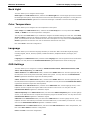
Language
This item allows you to select the language interface you would like. MPC-122-K offers eight languages,
including English, French, German, Spanish, Traditional Chinese, Simplified Chinese, Norwegian, and
Japanese.
Language: Press OSD Control button, and then select Language item. Use the up/down arrows to select the
language. You may also turn the Potentiometer Button rightward/leftward to select the language.
OSD Settings
This item allows you to configure five settings: OSD Horizontal Position, OSD Vertical Position, OSD
Timer, OSD Transparency, and OSD Lock.
OSD H. Position: Press OSD Control button, and then select OSD H. Pos. item. Use the right/up arrows, or
the left/down arrows to adjust the horizontal position of the panel. You may also turn the Potentiometer
Button rightward or leftward to adjust the horizontal position.
OSD V. Position: Press OSD Control button, and then select OSD V. Pos. item. Use the right/up arrows, or
the left/down arrows to adjust the vertical position of the panel. You may also turn the Potentiometer Button
rightward or leftward to adjust the vertical position.
OSD Timer: Press OSD Control button, and then select OSD Timer item. Use the right/up arrows, or the
left/down arrows to adjust how long the OSD screen will show on the screen. You may also turn the
Potentiometer Button rightward or leftward to adjust.
OSD Transparency: Press OSD Control button, and then select OSD Transparency item. Use the right/up
arrows, or the left/down arrows to adjust the transparency degree of the OSD screen. You may also turn the
Potentiometer Button rightward or leftward to adjust.
OSD Lock: Press OSD Control button, and then select OSD Lock item. Use the right/up arrows, or the
left/down arrows to select ON if you would like to lock the OSD screen, or select OFF if you would not.. You may
also turn the Potentiometer Button rightward or leftward to select.
OSD Password: Press OSD Control button, and then select OSD Password item. Enter the password, and
then select Save & Exit to finish the configuration.
Exit: Select Exit to leave this configuration.
B-3
MPC-122-K Hardware
On Screen Display Configuration
Information
This item allows you to view the current resolution and the recommended resolution of the panel. Meanwhile,
you can also view the firmware version in this item. Press OSD Control button, and then select Information
item to view the information of the panel.
System Power
This item allows you to shutdown the system power. Press OSD Control button, and then select System
Power item. Select System POW OFF, the system power will off. Select Exit to leave this configuration.
Reset to Default
This item allows you to reset to default value. Press OSD Control button, and then select Reset to Default
item. All settings will be restored to its factory default values.
Exit
This item allows you to leave the OSD configuration. Press OSD Control button, and then select Exit item to
finish the configuration.
B-4
C
C.
ECDIS Library and API Development
The MPC-122-K-ECDIS is approved for ECDIS. To receive ECDIS approval, each individual computer must be
measured, with the measurements stored individually in each computer. Each computer will have its own RGB
table consisting of the colors and backlight values required by the customer’s ECDIS application. Note that you
should NOT disconnect the computer from the panel of the MPC-122-K. If the computer and panel are
disconnected, the ECDIS API Library will not work.
This appendix explains how to install the ECDIS API and the contents of the ECDIS API. The following topics are
covered:
Installation
Source Tree
ECDIS Library
Backlight Function
ECDIS RGB Data Structure
ECDIS RGB Functions
MPC-122-K Hardware
ECDIS Library and API Development
Installation
The ECDIS API is included on the CD ROM. Copy the file to your development machine and use the appropriate
Windows tool to extract the zip file to your target folder. Note that the ECDIS API is only for Windows systems.
Source Tree
The following files will be extracted from the zip file.
mxecdis
Working Directories
MXECRGB.sys
driver for retrieving the RGB table
mxecdis.dll
ECDIS DLL
mxecdis.lib
ECDIS API LIB
MXECDISRGB.h
API header file for retrieving the RGB table
MXMPC122K.h
backlight API header file
sample
ECDIS API demo program source folder
You can refer to files in the sample directory to help using the ECDIS API in your own programs.
ECDIS Library
Programming functions for backlight settings and RGB table retrieval are introduced in this section.
Backlight Function
In an ECDIS system, each color table (DAY, DUSK, or NIGHT) has its own backlight value. This section
describes how to use the function to set the backlight.
mpc122k_set_backlight function
This function is used to configure the backlight of the MPC-122-K-ECDIS.
int mpc122k_set_backlight(int backlight);
Inputs
backlight
Specifies the backlight value ranged from 0 ~ 100.
Return Value
Returns 0, if successful;
Returns -1 in case of error
ECDIS RGB Data Structure
ECDIS RGB functions provide the method used to retrieve the RGB tables from an MPC-122-K-ECDIS computer.
This data structure defines the RGB tables and backlight values for DAY, DUSK, and NIGHT.
#define MAX_COLOR_TOKEN
63
typedef struct _ECDIS_RGB
{
unsigned char
DATE_TIME[12]; /* YYYYmmddHHMM, ASCII, 24h */
unsigned char
RGB_TB_DAY[MAX_COLOR_TOKEN][3];
unsigned char
RGB_TB_DUSK[MAX_COLOR_TOKEN][3];
unsigned char
RGB_TB_NIGHT[MAX_COLOR_TOKEN][3];
unsigned char
RGB_BKL[3];
} ECDIS_RGB, *PECDIS_RGB;
C-2
MPC-122-K Hardware
ECDIS Library and API Development
MAX_COLOR_TOKEN indicates the maximum number of colors in one color table. This parameter is defined
according to IHO-S52 Specifications.
<DATE_TIME> Specifies the calibration time of this computer
<RGB_TB_DAY> Specifies the DAY color table; (RGB_TB_DAY[n][0], RGB_TB_DAY[n][1], RGB_TB_DAY[n][2])
indicates the color of R, G, and B.
<RGB_TB_DUSK> Specifies the DUSK color table
<RGB_TB_NIGHT> Specifies the NIGHT color table
<RGB_BKL> Specifies the backlight values; RGB_BKL[0] is for DAY, RGB_BKL[1] is for DUSK, and RGB_BKL[2]
is for NIGHT.
ECDIS RGB Functions
mxecdis_rgb_read_tables function
This function reads the color tables from the MPC-122-K-ECDIS.
int mxecdis_rgb_read_tables(PECDIS_RGB rgb_data);
Inputs
rgb_data
Specifies the pointer of the RGB data structure.
Return Value
Returns 0, if successful;
Returns -1 in case of error
mxecdis_rgb_last_error function
This function returns the last error code for read RGB error.
unsigned long mxecdis_rgb_last_error();
Inputs
None.
Return Value
Returns the last error of the read RGB operation
C-3