1
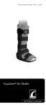
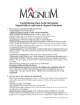
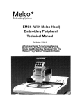
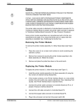
THE PHOENIX SERIES
MODEL 1850 KNEE CPM
OPERATOR MANUAL
6312 Seeds Road
Grove City OH 43123
Phone: 800.273.5233
Fax: 614.871.9353
WWW.KNEECPM.COM
Knee CPM Introduction
Thank you for choosing the Model 1850 Knee CPM by THE FURNISS CORPORATION, LTD.
The Model 1850 provides effective continuous passive motion therapy to the post operative or injured
knee. The open carriage design provides a comfortable fit and accommodates adult and pediatric (petite)
patient sizes. The control pendant is easy to understand and allows both staff and patient to change settings easily. Sturdy, mild steel construction, compact design and overall functionality make the Phoenix
Model 1850 ideal for hospital and home environments.
Read before operating or adjusting the Phoenix Model 1850 Knee CPM.
It is recommended that all clinicians and support personnel responsible for the proper operation of the
Model 1850 Knee CPM become thoroughly familiar with its capabilities and proper operating procedures
prior to actual patient use. Please contact customer service at 800.273.5233 with questions or visit our
digital headquarters at www.KneeCPM.com for online training options.
Safety Precautions
1.
Read and understand all instructions.
2.
Follow all warnings and instructions marked on the product.
3.
Connect power supply to grounded electrical outlets only. Use surge protector
to further protect your unit.
4.
Never touch any exposed or uninsulated wires or terminals unless the transformer
has been unplugged.
5.
Unplug this product from the wall outlet before cleaning. Do not use liquid or
aerosol cleaners. Use only a damp cloth.
6.
Do not use product near water.
7.
This product should only be operated from the type of power source indicated on
the label.
8.
Do not allow anything to rest on the power cord. Do not place the power cord in a location where
a person may trip, damage or move equipment over or near it.
9.
Do not overload or use extension cords as this may result in the risk of fire or
electric shock.
10.
If at anytime during the therapy the patient experiences extreme pain or
discomfort-STOP-turn the unit off and consult their physician.
11.
Unplug the unit from the wall outlet and refer to qualified personnel under the
following conditions:
-If the power cord is damaged
-If liquid is spilled into the product
-If the unit has been exposed to rain or water
-If the unit has been dropped or the frame has been damaged
-If a change in performance is noted
-If the unit does not operate normally by following the operating instructions
12.
Adjust only the controls that are covered by the operating instructions.
13.
Warning: Equipment not suitable for use in presence of a flammable anesthetic mixture with
air, oxygen or nitrous oxide.
14.
Warning: Keep ballscrew assembly clear of obstruction.
Unpacking your Model 1850 CPM
When receiving your Model 1850, examine the container and unit and report any substantial damage to
the shipper. Do not discard your shipping container - it provides required protection for your unit during
shipping and must be used when returning your unit for any warranty service. Unapproved or badly
damaged containers will be replaced and billed accordingly.
CPM Shipping Carton
Part No. Skit 1824
Container Contents
>
>
>
>
>
CPM Cradle Assembly with Control Pendant
Foot Cradle Assembly
Two (2) Bed Stabilizer Rods
One (1) Set of 1828-1 Patient Softgoods
Operators Manual, Quick Reference Guide, Training CD
Remove the Knee CPM from the container and slide the Foot Cradle Assembly out. Loosen the large
knobs on the Foot Cradle Assembly and position in the upright position. Tighten knobs.
Features
Foot Cradle Assembly
Calf Length
Adjustment Knobs (2)
Thigh Length
Adjustment Knobs (2)
Control Box
Foot Cradle
Adjustment Knobs (2)
Bed Stabilizer Rods (2)
Model 1850 Control Pendant
Softgoods Application
FURNISS Softgoods - 1828-1 - are designed specifically for use with Furniss Knee CPM devices.
Softgoods provide a 'troughing' effect allowing proper alignment of the limb and a truer fit overall.
Constructed with the highest quality materials, FURNISS softgoods provide superior comfort and support
for the patient.
Each Patient Softgoods kit includes five (5) pads total:
1 - Foot Boot
1 - Calf Pad
1 - Thigh Pad
2 - Auxiliary Straps
Slide the pocket of the foot boot over the end of the foot plate and secure to the
velcro.
Secure ankle support straps on the foot boot to the foot assembly tubes on both
sides.
TROUGH
TROUGH
The calf pad is the smaller of the two square-shaped pads. Position the calf
pad so that the cut-out is facing the thigh cradle. Peel the velcro strapping from
the back of the pad, loop over the cradle bar of the unit and secure to the back
of the softgood. Be sure not to pull the softgood tight, forming a trough to allow
for proper alignment.
The thigh pad is the larger of the two square-shaped pads. Position the thigh
pad so that the cut-out is facing the calf pad (the cut-outs will form a 'diamond'
shape). Begin with the tab Velcro at the very end of the thigh pad. Secure this
piece to the bottom of the thigh block**. Peel the rest of the Velcro strapping
from the back of the pad, loop over the cradle bar of the unit and secure to the
back of the softgood. Be sure to 'trough' the softgood, do not pull the softgood
tight.
** thigh block
The two (2) auxiliary straps may be used to secure the thigh and/or calf (do not secure too tightly...leave
room for shifting).
FURNISS softgoods are intended for single patient use only. Should the pads become soiled during use,
spot clean by hand with mild detergent and warm water.
FURNISS softgoods are designed specifically for use with the Knee CPM Series. Use of any other brand of
CPM Softgoods may adversely affect performance of the Knee CPM device and result in discomfort or
injury to the patient. Reorder number for the FURNISS softgoods: SKIT 1828-1.
Patient Setup
Correct measurement and adjustments are required to ensure patient comfort and compliance and to achieve
desired range of motion. Check that the unit is at 0 degrees during patient setup.
Note:
Use only on a stable surface.
An unstable surface could result in injury to patient and damage to the device.
FITTING THE PATIENT
•
Determine the length of the patient’s femur by measuring from the greater trochanter (hip joint) to the center or
joint line of the knee.
•
Transfer this measurement to the thigh cradle beginning approximately 1.5 to 2 inches away from the hip pivot
assembly measuring to the knee axis of the unit. Adjust the thigh cradle to match this measurement by loosening the thigh adjustment knobs and sliding the thigh cradle to the proper length.
•
Loosen the calf cradle adjustment knobs and extend the foot assembly. Do not remove this assembly -- only
slide far enough for patient placement. Position the patient's leg in the unit, with softgoods in place.
•
Slide the foot assembly toward patient accordingly leaving one half inch gap between the patient’s foot and the
foot plate. Tighten the calf cradle adjustment knobs securely.
•
The foot assembly may be adjusted in plantar flex or dorsi flex positions. Loosen the adjustment knobs on the
foot assembly, adjust the foot plate to the desired positioning and securely tighten the adjustment knobs.
Remember: The goal is to align the knee axis of the patient with the knee pivot axis of the CPM
Foot assembly adjustment knobs (2)
Calf adjustment knobs (2)
Knee pivot axis of unit
Thigh adjustment knobs (2)
Hip pivot assembly
Patient Setup
BED STABILIZING SYSTEM
Bed stabilizer rods are included in the base of the Phoenix Knee CPM. This system, in conjunction with the nonskid pad located on the bottom of the control box, effectively prevents migration or "movement" of the unit while on
a patient.
•
Loosen the base knobs, extend the rods to the appropriate length and tighten the knobs securely.
•
Stabilize the rods against a solid barrier such as a foot board.
Bed stabilizer rods (2)
Base knobs (2)
PEDIATRIC AND PETITE PATIENT ADJUSTMENT
The Furniss Knee CPM can adjust easily to accommodate pediatric and petite patients.
•
Loosen the calf adjustment knobs and slide the foot assembly out of the cradle.
•
Loosen the foot assembly adjustment knobs (do not remove).
•
Rotate both foot tubes 180 degrees so that they are facing the opposite direction. Tighten the foot assembly
adjustment knobs.
•
Slide cradle back into the device and secure with the calf adjustment knobs.
•
Note: You may apply a strip of adhesive-backed loop Velcro to this side of the footplate for added stability of
the foot boot softgood.
Pediatric and Petite Patient Setup
Operating the Phoenix 1850 CPM
POWER ON AND OFF
The ON/OFF switch is located at the base of the black control box. When the unit is powered ON it will beep one
(1) time and the hand-held control pendant will illuminate. This indicates that the unit is ready for use.
PHOENIX MODEL 1850 KNEE CPM CONTROL PENDANT
The Model 1850 control pendant includes of the following functionalities:
•
•
•
•
•
•
Flexion: 0 to 110 degrees
Extension: -5 to 105 degrees
Speed: 1 degree per second at lowest setting, 3 degrees per second at highest setting
Pause: 0 to 30 Seconds*
Patient Compliance Meter
Patient Lock Out Switch
To set Flexion range: Depress the FLX button and the up or down arrow simultaneously.
To set Extension range: Depress the EXT button and the up or down arrow simultaneously. A 5 degree difference between flexion and extension is required for normal operation.
Should the angle settings be too close the incorrect setting on the pendant will flash.
To set Speed: Depress the Speed button and the up or down arrow simultaneously. When you depress the Speed
button, the setting will appear in the ROM window.
To set *Pause: Depress the Pause button and the up or down arrow simultaneously. When you depress the Pause
button, the setting will appear in the ROM window.
Patient Compliance Meter: The patient compliance meter monitors patient usage and tracks in tenths of an hour
readings. Example: 25.4 reading = 25 hours and 24 minutes.
- Meter is displayed in the Flexion window
- The meter is read by depressing the FLX and SPD buttons simultaneously
- Clear meter by depressing the EXT, FLX, SPD and Pause buttons simultaneously.
Note: The Start/Stop button must be pressed in order to lock in setting changes.
PHOENIX MODEL 1850 CONTROL PENDANT OVERVIEW
Range of Motion (ROM) window
Flexion window
Flexion button
Extension window
Speed button
Extension button
Patient must have access to the
hand-held control pendant at all
times. The Stop/Start button allows
patient to stop the unit as needed.
As a safety feature, the unit will travel
in the opposite direction when the
button is depressed again.
*Pause button
Patient Lock-Out function:
The lock-out switch is located on the back of the control
pendant under the plastic door cover. To prevent
inadvertent changes to pendant settings, simply slide the
switch to the locked position. The ROM window will read
'LOC' should attempt be made to adjust settings when this
is in place. The stop/start button functionality remains the
same.
*Pause option:
Phoenix Models are set to pause at the end of
flexion and extension cycles. This setting can be
changed to pause the Phoenix in extension only.
See page 2-2 for details on this procedure.
CPM Care & Cleaning
Clean the CPM by using a mild disinfectant. Do not use aerosol cleaners or pour liquids directly on the unit. Use
only a damp cloth.
Items listed below should be inspected, cleaned or replaced depending on their condition or appearance.
Cables:
•
Potentiometer Cable
•
Pendant Cable
•
Power Supply Cable
Labels:
Control Pendant Label
Control Box Label
Serial Number Label
•
•
•
Velcro:
Footplate Velcro - 6”
Plastic Hip Pivot Velcro—1” (Underneath)
Control Pendant Velcro Strap
Power Cord (Transformer) Velcro Strap
Control Pendant Cable Strap
•
•
•
•
•
Skid Pads:
Skid Pad under Control Box
•
Knobs & Screws:
•
(4) Smaller Male Knobs for Thigh and Calf carriage adjustments
•
(2) Large Female Knobs for Foot Plate adjustment
•
(2) Smaller Male Knobs for Bed Mount Rods
•
(4) Pendant Screws (Inside of Control Pendant)
•
Check tightness of all Allan Head Screws on front & back End Caps
Track Seals:
Clean & Check for tears - replace as needed
•
Clean:
Chrome parts should be polished using a chrome cleaner and polish purchased at most automotive stores
Wipe or clean all cords
Clean outside of Control Pendant and other areas that are dirty
•
•
•
Product Specifications
Weight
26 Pounds
Length
28 Inches
Adjustable Length
42 Inches
Width
13 Inches
Range of Motion
-5 to 110 Degrees
Pause
0 to 30 Seconds
Limb Length
20 to 42 Inches
Calf Length
11 to 24 Inches
Thigh Length
9 to 18 Inches
>
Voltage 120 Volts AC input/60 Hz/14 Volts [email protected] amp
>
ENVIRONMENTAL CONDITIONS FOR TRANSPORTATION AND STORAGE
Recommended Ranges:
-Temperature range within –40o C to +70o C
-Relative humidity range within 10% to 100%
-Atmospheric pressure range within 500 to 1060 hPa
Warranty Information
LIMITED WARRANTY
The Furniss Corporation, Ltd. (Furniss Corp) warrants to the original buyer of this Knee CPM machine (the Unit)
that the Unit will be free from defects in material or workmanship for a period of Two Years from the date of original
purchase from FURNISS CORP. This warranty does not cover defects resulting from damage by accident, abuse,
misuse, misapplication, or unauthorized repairs or alterations made either by the customer or another party. The
Furniss Corporation reserves the right to determine whether the defective product falls into this category. The Furniss Corporation makes no other warranties, expressed or implied (including, without limitation merchantability, fitness for a particular purpose, or against infringement of any patent), except expressly provided herein.
If the Unit does not conform to this warranty, The Furniss Corporation will at its option repair or replace the defective Unit. The remedy of repair or replacement is purchasers’ sole and exclusive remedy and will satisfy all of FURNISS CORP’S liabilities, whether based on contract, tort, product liability, strict liability, or otherwise. In no event shall
its liability in connection with any defective Unit exceed the sales price of such unit.
For this limited warranty to apply, buyer must provide Furniss Corp with written notice of a claimed defect within
thirty (30) days after the discovery, but no later than the expiration date of the warranty term. Within reasonable
time following the receipt of such a notice, The Furniss Corporation will advise the purchaser of the disposition of
the Unit. Unless expressly authorized in writing, the defective Unit must be returned to The Furniss Corporation for
coverage. Furniss Corp reserves the right to inspect the Unit to determine the claimed defect is within the coverage
of this limited warranty.
www.furnisscorp.com
RETURNING YOUR CPM FOR REPAIR
•
Do not discard the original packaging of your Phoenix Knee CPM. It provides required protection for your unit
during shipping and must be used when returning your unit for service. Damages resulting from packaging unit
in anything other than the required Phoenix container are the responsibility of the owner. Unapproved or badly
damaged device containers will be replaced and billed accordingly.
•
Return Authorization Numbers are required. Contact Customer Support at 800.273.5233 with Serial Number,
contact information and required repair description.
•
Ship your unit to the Technical Service Department at:
THE FURNISS CORPORATION, LTD.
ATTN: (RA NUMBER)
6312 SEEDS ROAD
GROVE CITY, OH 43123
Model 1850 Knee CPM Operators Manual
Section 2 - Service & Maintenance
TABLE OF CONTENTS
PAGE
Calibration Procedure
2-2
Pause Option Procedure
2-2
Motor Only Preventative Maintenance Procedure
3-2
Knee Potentiometer Assembly Replacement Procedure
4-2
Motor & Gearbox Replacement Procedure
5-2
On/Off Switch Replacement Procedure
6-2
Power Supply Replacement Procedure
7-2
Track Seal Replacement Procedure
8-2
Replacement Parts List
9-2
Quick Reference Guide
10-2
Phoenix Model 1850 Knee CPM
Calibration Procedure
--Pause Option Procedure
Use this procedure when:
* Replacing the circuit board
* Replacing the knee potentiometer assembly
Tools required:
Protractor, Phillips Head Screwdriver, & 3/32 Allen Wrench
Procedure:
* Remove control box cover
* Remove kneepot cover
* Power up unit and listen for one audible beep.
1. Locate the slide switch (SW1) on the main circuit board. Move the switch from 'RUN'
position to the 'CAL' position.
2. Using the up or down arrows on pendant, move the leg cradle to 0.
- Position a straight-edged tool (or item such as a ruler) on top right or top left
side of leg cradle. Unit is at 0 when the tool is even or 'flat' on the cradle.
3. Loosen the potentiometer clamps and gently turn the knee potentiometer. Observe the
pendant display - the degree range indicator light (red dot) will appear in the
Extension window. Continue to adjust the knee potentiometer until you have achieved a
range reading of 2480 - 2500 . Stop adjusting and tighten the potentiometer clamps.
4. Press and hold EXT button until beeper sounds indicating that the 0 position is set.
5. Move cradle angle to 90 using the up arrow on pendant.
- Use a protractor to determine the 90 angle.
6. The degree range indicator light (red dot) will appear in the Flexion window indicating that the unit is
within range.
7. Press and hold the FLX button until the beeper sounds indicating that the 90 position is set.
8. Slide switch on the main circuit board back to 'RUN' position.
9. After calibration is complete, set the speed and range of motion to the desired setting and
press the STOP/START button on pendant to lock in settings.
Flexion Pause add/remove procedure:
1.
2.
3.
4.
5.
Turn the unit on and slide the switch on the circuit board from 'RUN' to 'CAL' position
If the unit is set for FLEXION PAUSE an 'F' will appear in the extension window.
To remove FLEXION PAUSE feature, press the “PAUSE” button.
To add FLEXION PAUSE feature, press the “PAUSE” button.
Slide the switch on the circuit board back to 'RUN' position.
Toll Free 800.273.5233
614.871.1470
Fax: 614.871.1470
Knee CPM Series
Only - Preventative
Preventative Maintenance
Procedure
AMotor
Simple
Maintenance
Procedure to Clear the Carbon from the
Phoenix Motor
Blow air through the gaps
Phillips Head Screws
1 2
Allen Screws
3
Plug
Plug
Tools Required:
-9/64 Allen Wrench
-Phillips Head Screwdriver
-Compressed Air
Instructions:
1. Turn the power off to the unit.
2. Unplug the motor from the circuit board
3. Using the 9/64 Allen Wrench remove the allen screws that hold the Drive
Assembly.
4. Remove the Drive Assembly.
5. Loosen the PhillipsHead Screws enough to create a gap between the 3
sections of the motor.
Be careful not to remove the screws
6. Blow enough air through the gaps (3) to clear the carbon build up.
7. Tighten the screws enough to secure the sections.
8. Return the Drive Assembly and test the unit.
1/9/03 LM
To:______________________________________________
Company:________________________________________
Fax:_____________________________________________
Phoenix Knee CPM Series
Knee Potentiometer Assembly Replacement Procedure
Toll Free 800.273.5233
614.871.1470
Fax: 614.871.1470
Replacing the Knee Potentiometer Assembly
POTENTIOMETER
PLATE FASTENER
POSITIONING
HOLE
POTENTIOMETER
CABLE
CALF SECTION
POTENTIOMETER
KEY PIN
TH
POSITIONING
PIN
SE
C
TI
ON
Motor
J1 J2
J3
POTENTIOMETER
KEY
Tools Required:
Phillips Screwdriver, 3/4 inch open-end
wrench
J4
J5
0 90 PAUSE
Calibration
N/A
Pendant
Power
IG
H
J6
Knee
Knee
Potentiometer
Potentiometer
1. Turn the Power Switch OFF.
2. Remove the Control Box Cover. (5 Phillips
Screws)
3. Unplug the Potentiometer Cable from J6 on the
Circuit Board.
4. Loosen the Strain-relief from the Potentiometer
(POT) and Pendant Cables.
5. Remove the Strain-relief Plate.
6. Remove the Potentiometer Cover (2 Screws)
6. Unscrew the POT Plate fastener.
7. Remove the POT Plate.
8. Press the new POT Assembly Plate onto the
Positioning Pin of the calf section. Be careful to
align the KEY with the KEY PIN on the Thigh
Section.
9. Secure the POT plate with the fastener.
10. Replace the POT and Pendant Cables. Secure
the Strain-relief Plate.
11. Plug the POT Cable into J6 on the Circuit Board.
12. Calibrate the Machine by following the
Calibration instructions.(Page 2)
1/9/03 LM
To:______________________________________________
Company:________________________________________
Fax:_____________________________________________
Phoenix Knee CPM Series
614.871.1470 Fax: 614.871.1470
Motor & Gearbox
Replacement Procedure
Toll Free 800.273.5233
Replacing the Motor & Gearbox
Tools required:
Phillips Head Screwdriver, Small Flat Head
Screwdriver, 9/64th Allen Wrench
1. Turn the Power Switch OFF.
2. Remove the Control Box Cover. (5 Phillips
Screws)
3. Unplug the Motor from the Circuit Board.
4. Remove the Motor and gearbox assembly using the Allen
Wrench to unscrew the two(2) screws from the motor
mounting bracket.
5. Unplug the gearbox coupling from the rubber coupler.
6. Remove the motor mount bracket by removing the (4)
Allen screws from the rubber bushings..
7. Attach the NEW motor and gearbox.
8. Plug the coupling into the rubber coupler.
9. Secure the motor mounting bracket with the two (2)
screws.
10. Plug in the motor to the Circuit Board.
11. Replace the top cover.
Rubber Bushing Allen Screws (4)
Motor Mount Bracket
Allen Screws (2)
Rubber Coupler
Motor
J1 J2
J4
J5
0 90 PAUSE
Calibration
N/A
Plug
Pendant
Power
J3
J6
Knee
Potentiometer
1903 LM
To:______________________________________________
Company:________________________________________
Fax:_____________________________________________
Phoenix Knee
CPM Series
614.871.1470 Fax: 614.871.1470
On/Off Switch Replacement Procedure
Toll Free 800.273.5233
Replacing the ON/OFF Switch
Writing on
TOP
FASTENING
CLIPS
WHITE WIRES
TO CIRCUIT
BOARD
FROM
POWER SUPPLY
BLACK WIRES
Tools Required:
Pliers
Caution: To avoid electric shock unplug the unit before beginning this
procedure.
1. Turn the Power Switch OFF and unplug unit from wall outlet.
2. Remove the Control Box Cover. (5 Phillips Screws)
3. Unplug the the 2 white and 2 black wires from the back of the
ON/OFF switch.
4. Use the pliers to squeeze the fastening clips and push the switch out.
5. Press the new ON/OFF switch into position.
6. Plug in the WHITE and BLACK wires as indicated above.(See
illustration)
7. Replace the cover.
1/9/03 LM
To:______________________________________________
Company:________________________________________
Fax:_____________________________________________
Phoenix Knee CPM Series
Toll
Free 800.273.5233
614.871.1470 Procedure
Fax: 614.871.1470
Power
Supply Replacement
Replacing the Power Supply
ON/OFF SWITCH
WHITE WIRE
TO CIRCUIT
BOARD
FROM
POWER SUPPLY
GROUND
WIRE
BLACK WIRE (GREEN)
Tools Required:
Pliers, Phillips Head Screwdriver
Caution: To avoid electric shock unplug the unit before beginning this
procedure.
1. Turn the Power Switch OFF and unplug the unit from wall outlet.
2. Remove the Control Box Cover. (5 Phillips Screws)
3. Unplug the white and black wires from the POWER SUPPLY side
of the of the ON/OFF switch. (See illustration)
4. Disconnect the green ground wire
5. Using the pliers squeeze the sides of the strain-relief. Push the strainrelief out.
6. Remove the power supply cord.
7. Thread the new Power Supply through the opening.
8. Replace the strain relief.
9. Plug in the white and black wires as indicated above. (See illustration)
10. Attach the green ground wire.
1/9/03 LM
To:______________________________________________
Company:________________________________________
Fax:_____________________________________________
Phoenix Knee CPM Series
Track Seal Replacement Procedure
Just touch the edge of the drive strut
Track Seals
Equipment required:
1. Track Seal Kit (Part No. Skit1707A)
Includes: 4 Track Seals & 2 Packets of adhesive
2. Adhesive remover & Alcohol
Attaching the Track Seals:
1. Remove the old track seal.
2. Clean off any adhesive residue from the old track seal. Surfaces must be cleaned thoroughly for the new track seal to adhere properly. Clean with adhesive remover (Goo-Gone)
and alcohol.
3. Attach the track seals to the edge of the track opening by sliding the open side of the new
track seal along the edge of the opening.
4. Lift the top side of the new track seal and apply a bead of adhesive (a little goes a long way)
along the full length of the entire strip.
Knee CPM Model 1850 Replacement Parts List
SKIT1223
SKIT1225
SKIT1231
SKIT1420
SKIT1511A
SKIT1600
SKIT1613
SKIT1707A
SKIT1724
SKIT1727
SKIT1734
SKIT1801
SKIT1804
SKIT1812
SKIT1823
SKIT1823A
SKIT1825
SKIT1834
SKIT1850
SKIT1906
SKIT3611
1850
2103
2104
Phoenix Hardware/Fastners
Pendant Start Stop Switch
Pendant Velcro Strap
Knee POT Assembly
Power Supply, Domestic
Foot Assembly
Knob Kit
Track Seals
Hip Pivot
Delron Spacer & Shoulder Bolt Kit
Motor & Gear Box (Phoenix)
Bed Tube Assembly
Cable Velcro Straps (pkg/5)
Skid Pad Kit
Phoenix POT Cover Kit (Includes Hardware & Label)
Phoenix POT Covers (3) Only
Phoenix ROM Label (Pkg of 10)
Phoenix Shipping Carton (Complete)
Pendant Assembly Complete (1850)
Motor Only
Velcro
Pendant Enclosure (1850)
Pendant Overlay (1850)
Pendant Cable (1850)
The Furniss Corporation
Technical Service Department
800.273.5233