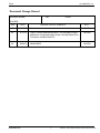
1
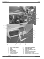
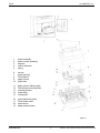
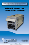
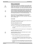
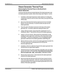
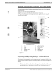
Printer
96-103925 Rev. 3.0
Printer
NEVER PULL PRINTER PAPER BACKWARDS THROUGH THE PRINTER.
THIS WILL DAMAGE THE PRINT HEAD.
STATIM L / 5000/ 5000S UNITS CONTAIN ELECTRONIC COMPONENTS
WHICH MAY BE DAMAGED OR DESTROYED BY ELECTRO-STATIC DISCHARGE (ESD). OBSERVE APPROPRIATE SAFEGUARDS WHEN SERVICING. ALWAYS TRANSPORT ELECTRONIC COMPONENTS AND ASSEMBLES IN STATIC-PROTECTED PACKAGING.
The printer cable connector is attached to Controller Board connector P2. If a
Transducer Interface Board is present, the printer cable connector is attached
to Transducer Interface Board connector P2. See, Pressure Transducer.
Some printer module assemblies are manufactured with a ferrite core
assembled to the cable. If so, ensure the ferrite core is in place when the
assembly is reinstalled. See, Positioning the Ferrite Core.
Removing the Printer Module
To remove the printer module assembly (1), follow these steps (see Figure
1):
1.
Place the cover (2) on a clean work surface to avoid scratching the
cabinetry surface.
2.
Remove four screws (3) securing the printer module assembly to the
fascia assembly (4). Retain the screws.
3.
Remove and place the printer face down on the work bench.
Replacing the Printer Module
To replace the printer module (1), follow these steps (see Figure 1):
CONFIDENTIAL
1.
Install the printer module assembly in the fascia assembly (4) using the
four screws (3) retained during disassembly.
2.
If the module contains a new Printer Interface Board, or a new printer
module, the print quality may require adjustment. See, Adjusting Print
Quality. See Printer Interface Board: Important Notes.
3.
Connect the printer cable connector to Controller Board (2) P2 or, if
present, Pressure Interface Board P2.
4.
Connect the LCD cable connector to Controller Board P3.
5.
Connect the keypad cable connector to Controller Board P4.
6.
Plug-in the unit power cord and turn the power switch ON.
1
STATIM L / 5000/ 5000S Cassette Autoclave Service Manual
96-103925 Rev. 3.0
Printer
13
14
12
5
8
6
2
7
1
3
4
11
1.
2.
3.
4.
5.
6.
7.
10
9
printer module assembly
cover
screws
fascia assembly
Controller Board
Printer Interface Board
#1 Phillips screws
8.
9.
10.
11.
12.
13.
14.
Printer Interface Board shield
Printer ribbon cable
Printer Controller ribbon cable
ferrite core
Controller Board P2 connector
Pressure Interface Board
Pressure Interface Board P2 connector
Figure 1
STATIM L / 5000/ 5000S Cassette Autoclave Service Manual
2
CONFIDENTIAL
Printer
96-103925 Rev. 3.0
Removing the Printer Interface Board
To remove the Printer Interface Board (6) from the module, follow these steps
(see Figure 1):
STATIM L / 5000/ 5000S UNITS CONTAIN ELECTRONIC COMPONENTS
WHICH MAY BE DAMAGED OR DESTROYED BY ELECTRO-STATIC DISCHARGE (ESD). OBSERVE APPROPRIATE SAFEGUARDS WHEN SERVICING. ALWAYS TRANSPORT ELECTRONIC COMPONENTS AND ASSEMBLES IN STATIC-PROTECTED PACKAGING.
1.
If detachable, disconnect the Printer Driver ribbon cable (9) and Printer
Interface ribbon cable (10). See Printer Interface Board: Important
Notes.
2.
Using a #1 Phillips screwdriver, remove the four screws (7) from the
Printer Interface Board. Retain the screws.
3.
Remove and retain the Printer Interface Board and the Printer Interface
Board shield (8). There may be four nylon spacers (not shown) between
the board and the stand-offs. See Printer Interface Board: Important
Notes.
Replacing the Printer Interface Board
To replace the Printer Interface Board, follow these steps (see Figure 1):
STATIM L / 5000/ 5000S UNITS CONTAIN ELECTRONIC COMPONENTS
WHICH MAY BE DAMAGED OR DESTROYED BY ELECTRO-STATIC DISCHARGE (ESD). OBSERVE APPROPRIATE SAFEGUARDS WHEN SERVICING. ALWAYS TRANSPORT ELECTRONIC COMPONENTS AND ASSEMBLES IN STATIC-PROTECTED PACKAGING.
CONFIDENTIAL
1.
Connect the Printer Interface ribbon cable (10) to Printer Interface Board
header P1. Cable assemblies may differ. If the connector is not polarized,
note the orientation of Pin 1 of the connector and Pin 1 of the board.
2.
Connect the Printer ribbon cable (9) connector to Printer Interface
Board header P2.
3.
Place the Printer Interface Board, component side down, on the
module. Replace the Printer Interface Board shield (8) and insert the
four screws (7) retained during disassembly.
4.
If the Printer Interface Board has been repaired, or is a new Printer
Interface Board, the print quality may require adjustment. See, Adjusting Print Quality. See Printer Interface Board: Important Notes.
3
STATIM L / 5000/ 5000S Cassette Autoclave Service Manual
96-103925 Rev. 3.0
Printer
Adjusting Print Quality
To remove the cover, see STATIM L / 5000/ 5000S Cover Removal and
placement.
Re-
STATIM L / 5000 / 5000SUNITS CONTAIN ELECTRONIC COMPONENTS
WHICH MAY BE DAMAGED OR DESTROYED BY ELECTRO-STATIC DISCHARGE (ESD). OBSERVE APPROPRIATE SAFEGUARDS WHEN SERVICING. ALWAYS TRANSPORT ELECTRONIC COMPONENTS AND ASSEMBLES IN STATIC-PROTECTED PACKAGING.
To alter print quality, the contrast adjustment pot (R21) located on the printer
Interface Board must be adjusted. Follow these steps (see Figures 1 and 2):
1.
Current versions of the Printer Interface Board have the printer contrast
adjustment pot (R21) located at the edge of the board, and adjustments
may be made using a small adjustment tool while the printer module is
still in the fascia assembly. (See Figure 1.)
Earlier versions require that the Printer Interface board be removed from
the back of the module before the pot is accessible. See, Removing the
Printer Controller Board and Printer Interface Board - Important Notes.
2.
To adjust and test print quality, turn the unit power switch ON. Open the
printer module and enable the printer by pressing the printer power
button (item 18, Figure 2). Start and then quickly stop a cycle. Doing so
causes an error message to be printed. While the error message is
printing, adjust the pot (R21).
3.
If further adjustment is required, repeat steps 1 and 2. Reinstall the
cover. See STATIM L / 5000/ 5000S Cover Removal and Replacement.
Removing the Printer
To remove the printer assembly (1) from the printer module assembly (2),
follow these steps (see Figure 2):
STATIM L / 5000/ 5000S PRINTED WIRING BOARDS AND MICROPROCESSORS ARE SENSITIVE TO STATIC ELECTRIC CHARGES. OBSERVE THE APPROPRIATE SAFEGUARDS FOR HANDLING AND
SERVICING STATIC SENSITIVE PARTS.
1.
Remove the printer module from the unit. See, Printer Removal and
Replacement, Removing the Printer Module.
2.
Remove the printer assembly from the printer module assembly. The
printer assembly is held into the module by two hinge pins (3). The pin on
the bottom left of the assembly sits in a recessed slot / retaining hole.
The pin on the bottom right hand of the assembly is captured by a snap
STATIM L / 5000/ 5000S Cassette Autoclave Service Manual
4
CONFIDENTIAL
Printer
96-103925 Rev. 3.0
1.
2.
3.
4.
5.
printer assembly
printer module assembly
hinge pin
snap mechanism
spring
6.
7.
8.
9.
10.
screws
printer housing
Printer Board
paper roll arm
printer door
11.
12.
13.
14.
15.
paper roll arm retaining clips
Printer Board mounting holes
mounting bosses
printer body
locating ribs
16.
17.
18.
19.
print head flexible cable
Printer ribbon cable
power button
paper advance button
Figure 2
CONFIDENTIAL
5
STATIM L / 5000/ 5000S Cassette Autoclave Service Manual
96-103925 Rev. 3.0
Printer
mechanism. Deflect the snap (4) away from the printer to free the hinge
pin, and swing the assembly out of the module housing.
3.
Remove the printer spring (5) from the left hand hinge pin and retain for
re-assembly.
4.
Using a #1 Phillips screwdriver, remove three screws (6) from the
printer housing (7) and set them aside for use in re-assembling the
printer.
5.
Remove the housing. Note the orientation of the Printer Board (8) and the
paper roll arm (9) assembled on the printer door (10).
6.
GENTLY lift the Printer Board upwards and away from the printer door.
EXERCISE CARE WHILE HANDLING THE BOARD. THE PRINTER IS
INTEGRAL TO THE WIRING BOARD. DO NOT PLACE STRAIN ON
THE CONNECTIONS OF THE RIBBON CABLE SOLDERED TO THE
BOARD.
7.
Remove the paper roll arm from the clips (11).
8.
Carefully rest the Printer Board beside the assembly.
Replacing the Printer
To replace the printer, follow these steps (see Figure 2):
STATIM L / 5000/ 5000S UNITS CONTAIN ELECTRONIC COMPONENTS
WHICH MAY BE DAMAGED OR DESTROYED BY ELECTRO-STATIC DISCHARGE (ESD). OBSERVE APPROPRIATE SAFEGUARDS WHEN SERVICING. ALWAYS TRANSPORT ELECTRONIC COMPONENTS AND ASSEMBLES IN STATIC-PROTECTED PACKAGING.
1.
Carefully snap the paper roll arm (9), in the loading position, back into the
clips (11) on the printer door.
2.
Place the Printer Board (8) back into position on the printer door (10).
Note the alignment of the printer board mounting holes (12) and the
mounting bosses (13) on the printer door. The black plastic printer body
(14) rests between the locating ribs (15) on the inside of the printer door.
3.
Check that the print head flex cable (16) and Printer ribbon cable (17) are
not pinched between the printer door and the wiring board.
4.
Place the printer housing (7) on the printer door (10). Check again to be
sure that the flexible cables are not pinched between the cover and the
door. The power button (18) and the paper advance button (19) must
protrude through the openings in the cover and operate freely.
5.
Using a #1 Phillips screwdriver secure the printer housing to the
STATIM L / 5000/ 5000S Cassette Autoclave Service Manual
6
CONFIDENTIAL
Printer
96-103925 Rev. 3.0
printer door with the three screws (6) retained during the disassembly
procedure. DO NOT OVER TIGHTEN THESE SCREWS.
6.
Place the printer spring (5) on the left hand hinge pin of the printer assembly, with the long tang positioned to align with the long slot on the
module housing.
7.
Place the left hand hinge pin in the recesses slot / retaining hole and
align the long spring tang. Swing the right hand hinge pin towards the
module housing and push firmly onto the snap mechanism (4).
8.
Connect the printer cable connector to Controller Board P2 or , if
present, Pressure Interface Board P2. See, Positioning the Ferrite Core.
9.
Connect the LCD cable connector to Controller Board P3.
10. Connect the keypad cable connector to Controller Board P4.
11. Power the unit ON. Load the thermal paper and test print. To test print
start and then quickly stop a cycle. See Installing Paper Into the
STATIM L / 5000/ 5000S Printer.
12. Reinstall the cover. See STATIM L / 5000/ 5000S Cover Removal and
Replacement.
Positioning the Ferrite Core
If the printer module assembly you are servicing was manufactured with a
ferrite core assembled to the cable, the core must be present during
reassembly. Position the core three to four inches from the printer module.
Apply two sided adhesive tape to the core and carefully place it on the fiche
paper shield on the back of the printer module so the cable is not unduly
strained, but will still reach either the P2 connector on the Controller Board, or
the P2 connector on the Transducer Interface Board..
Printer Interface Board - Important Notes
CONFIDENTIAL
1.
In order to operate with version 1.1 STATIM Controller Boards, Printer
Interface Boards version 2.0 and higher require the removal of jumper J2.
2.
Nylon spacers are required for mounting version 1.1 Printer Interface
Boards ONLY.
3.
To adjust the print contrast potentiometer R21 on Printer Interface Board
versions prior to 2.0, the Printer Interface Board must be removed from
the printer module assembly.
To adjust the print contrast potentiometer, R21, on Printer Interface
Board version 2.0, the printer module assembly must be removed from
the fascia.
To adjust the print contrast potentiometer, R21, on Printer Interface
7
STATIM L / 5000/ 5000S Cassette Autoclave Service Manual
96-103925 Rev. 3.0
Printer
Board versions 2.1 and later, R21 is accessible with the printer module
assembly installed in the fascia.
4.
Setting the printer contrast too dark on version 1.1 Printer Interface
Boards may cause the STATIM L / 5000/ 5000S to reset while printing
under low line-voltage conditions. If this problem occurs, adjust R21 to
lighten the print contrast, or upgrade to a later revision of Printer Interface
Board.
5.
The cable connecting the Printer Interface Board to the STATIM Controller
Board is permanently soldered to the Printer Interface Board on all
boards prior to version 2.2.
6.
Some version 1.1 Printer Interface Boards were fabricated with a strainrelief on the connector attaching to STATIM Controller Board position P2.
The strain-relief must be removed before connecting to STATIM Controller
Board versions 2.0 and later.
STATIM L / 5000/ 5000S Cassette Autoclave Service Manual
8
CONFIDENTIAL
Printer
96-103925 Rev. 3.0
Document Change Record
Document Number:
Title:
Printer
96-103925
REV.
DATE
1.0
96.05.29
New.
96-088
2.0
97.12.12
Figure 1 line art replaced with photo. Text changed to reflect
attachment of keyboard cable to either Controller Board P2 or
Transducer Interface Board P2.
98-0290
3.0
99.04.14
Added 5000S
99-0059
CONFIDENTIAL
DESCRIPTION OF CHANGES
9
ECO
STATIM L / 5000/ 5000S Cassette Autoclave Service Manual