1
User’s Manual of FGSW-2840 / FGSW-4840S
Trademarks
Copyright © PLANET Technology Corp. 2014.
Contents are subject to revision without prior notice.
PLANET is a registered trademark of PLANET Technology Corp. All other trademarks belong to their respective owners.
Disclaimer
PLANET Technology does not warrant that the hardware will work properly in all environments and applications, and makes no
warranty and representation, either implied or expressed, with respect to the quality, performance, merchantability, or fitness for
a particular purpose. PLANET has made every effort to ensure that this User's Manual is accurate; PLANET disclaims liability
for any inaccuracies or omissions that may have occurred.
Information in this User's Manual is subject to change without notice and does not represent a commitment on the part of
PLANET. PLANET assumes no responsibility for any inaccuracies that may be contained in this User's Manual. PLANET makes
no commitment to update or keep current the information in this User's Manual, and reserves the right to make improvements to
this User's Manual and/or to the products described in this User's Manual, at any time without notice.
If you find information in this manual that is incorrect, misleading, or incomplete, we would appreciate your comments and
suggestions.
FCC Warning
This equipment has been tested and found to comply with the limits for a Class A digital device, pursuant to Part 15 of the FCC
Rules. These limits are designed to provide reasonable protection against harmful interference when the equipment is operated
in a commercial environment. This equipment generates, uses, and can radiate radio frequency energy and, if not installed and
used in accordance with the Instruction manual, may cause harmful interference to radio communications. Operation of this
equipment in a residential area is likely to cause harmful interference in which case the user will be required to correct the
interference at his own expense.
CE Mark Warning
This is a Class A product. In a domestic environment, this product may cause radio interference, in which case the user may be
required to take adequate measures.
Energy Saving Note of the Device
This power required device does not support Standby mode operation. For energy saving, please remove the power cable to
disconnect the device from the power circuit. In view of saving the energy and reducing the unnecessary power consumption, it
is strongly suggested to remove the power connection for the device if this device is not intended to be active.
WEEE Warning
To avoid the potential effects on the environment and human health as a result of the presence of hazardous
substances in electrical and electronic equipment, end users of electrical and electronic equipment should
understand the meaning of the crossed-out wheeled bin symbol. Do not dispose of WEEE as unsorted
municipal waste and have to collect such WEEE separately.
Revision
PLANET 24/48-Port 10/100TX + 4-Port Gigabit Managed Switch User's Manual
FOR MODELS: FGSW-2840(V1) / FGSW-4840S (V3)
REVISION: 1.0 (September 2014)
Part No: EM-FGSW-2840_FGSW-4840S_v1.0
2
User’s Manual of FGSW-2840 / FGSW-4840S
TABLE OF CONTENTS
1. INTRODUCTION.................................................................................................................... 9
1.1 Package Contents ........................................................................................................................................9
1.2 Product Description ...................................................................................................................................10
1.3 How to Use This Manual ............................................................................................................................11
1.4 Product Features........................................................................................................................................12
1.5 Product Specifications ..............................................................................................................................14
2. INSTALLATION ................................................................................................................... 17
2.1 Hardware Description ................................................................................................................................17
2.1.1 Switch Front Panel ..............................................................................................................................................17
2.1.2 LED Indications ...................................................................................................................................................18
2.1.3 Switch Rear Panel ...............................................................................................................................................20
2.2 Installing the Switch...................................................................................................................................21
2.2.1 Desktop Installation .............................................................................................................................................21
2.2.2 Rack Mounting.....................................................................................................................................................22
2.2.3 Installing the SFP transceiver ..............................................................................................................................23
3. SWITCH MANAGEMENT .................................................................................................... 26
3.1 Requirements..............................................................................................................................................26
3.2 Management Access Overview .................................................................................................................27
3.3 Web Management .......................................................................................................................................27
3.4 SNMP-based Network Management .........................................................................................................28
4. WEB CONFIGURATION ...................................................................................................... 29
4.1 Main Web Page ...........................................................................................................................................32
4.2 System.........................................................................................................................................................34
4.2.1 System Information..............................................................................................................................................34
4.2.1.1 System Summary ......................................................................................................................................35
4.2.1.2 Device Description.....................................................................................................................................36
4.2.1.3 System Time..............................................................................................................................................37
4.2.1.4 Daylight Saving Time.................................................................................................................................38
4.2.1.5 System IP ..................................................................................................................................................39
4.2.2 User Management ...............................................................................................................................................41
4.2.2.1 User Table .................................................................................................................................................42
3
User’s Manual of FGSW-2840 / FGSW-4840S
4.2.2.2 User Config ...............................................................................................................................................42
4.2.3 System Tools .......................................................................................................................................................44
4.2.3.1 Config Restore ..........................................................................................................................................45
4.2.3.2 Config Backup ...........................................................................................................................................46
4.2.3.3 Firmware Upgrade.....................................................................................................................................47
4.2.3.4 System Reboot ..........................................................................................................................................48
4.2.3.5 System Reset ............................................................................................................................................49
4.2.4 Access Security ...................................................................................................................................................50
4.2.4.1 Access Control ..........................................................................................................................................51
4.2.4.2 SSL Config ................................................................................................................................................53
4.2.4.3 SSH Config................................................................................................................................................55
4.3 Switching.....................................................................................................................................................61
4.3.1 Port ......................................................................................................................................................................62
4.3.1.1 Port Config ................................................................................................................................................63
4.3.1.2 Port Mirror .................................................................................................................................................65
4.3.1.3 Port Security..............................................................................................................................................68
4.3.1.4 Port Isolation .............................................................................................................................................70
4.3.1.5 Loopback Detection...................................................................................................................................72
4.3.2 LAG .....................................................................................................................................................................74
4.3.2.1 LAG Table..................................................................................................................................................75
4.3.2.2 Static LAG .................................................................................................................................................77
4.3.2.3 LACP Config..............................................................................................................................................78
4.3.3 Traffic Monitor ......................................................................................................................................................81
4.3.3.1 Traffic Summary ........................................................................................................................................82
4.3.3.2 Traffic Statistics..........................................................................................................................................83
4.3.4 MAC Address.......................................................................................................................................................85
4.3.4.1 Address Table ............................................................................................................................................86
4.3.4.2 Static Address............................................................................................................................................88
4.3.4.3 Dynamic Address.......................................................................................................................................90
4.3.4.4 Filtering Address........................................................................................................................................92
4.3.5 DHCP Filtering.....................................................................................................................................................94
4.4 VLAN............................................................................................................................................................98
4.4.1 IEEE 802.1Q VLAN .............................................................................................................................................99
4.4.2 VLAN Config......................................................................................................................................................102
4.5.1 STP Config ........................................................................................................................................................ 119
4.5.1.1 STP Config ..............................................................................................................................................120
4.5.1.2 STP Summary .........................................................................................................................................122
4.5.2 Port Config.........................................................................................................................................................124
4.5.2.1 Port Config ..............................................................................................................................................125
4
User’s Manual of FGSW-2840 / FGSW-4840S
4.5.3 MSTP Instance ..................................................................................................................................................127
4.5.3.1 Region Config..........................................................................................................................................128
4.5.3.2 Instance Config........................................................................................................................................129
4.5.3.3 Instance Port Config ................................................................................................................................131
4.5.4 STP Security......................................................................................................................................................133
4.5.4.1 Port Protect .............................................................................................................................................134
4.5.4.2 TC Protect ...............................................................................................................................................136
4.6 Multicast ....................................................................................................................................................137
4.6.1 IGMP Snooping .................................................................................................................................................140
4.6.1.1 Snooping Config ......................................................................................................................................142
4.6.1.2 Port Config ..............................................................................................................................................143
4.6.1.3 VLAN Config............................................................................................................................................144
4.6.1.4 Multicast VLAN ........................................................................................................................................146
4.6.2 Multicast IP ........................................................................................................................................................148
4.6.2.1 Multicast IP Table ....................................................................................................................................149
4.6.2.2 Static Multicast IP ....................................................................................................................................150
.4.6.3 Multicast Filter ..................................................................................................................................................152
4.6.3.1 IP-Range .................................................................................................................................................153
4.6.3.2 Port Filter.................................................................................................................................................154
4.6.4 Packet Statistics ................................................................................................................................................156
4.6.4.1 Packet Statistics ......................................................................................................................................157
4.7 QoS ............................................................................................................................................................159
4.7.1 DiffServ..............................................................................................................................................................163
4.7.1.1 Port Priority..............................................................................................................................................164
4.7.1.2 802.1P/CoS mapping ..............................................................................................................................165
4.7.1.3 DSCP Priority ..........................................................................................................................................166
4.7.1.4 Schedule Mode .......................................................................................................................................167
4.7.2 Bandwidth Control .............................................................................................................................................168
4.7.2.1 Rate Limit ................................................................................................................................................169
4.7.2.2 Storm Control ..........................................................................................................................................171
4.7.3 Voice VLAN .......................................................................................................................................................173
4.7.3.1 Global Config...........................................................................................................................................176
4.7.3.2 Port Config ..............................................................................................................................................177
4.7.3.3 OUI Config...............................................................................................................................................179
4.8 ACL ............................................................................................................................................................181
4.8.1 ACL Config ........................................................................................................................................................182
4.8.1.1 ACL Summary .........................................................................................................................................183
4.8.1.2 ACL Create ..............................................................................................................................................184
4.8.1.3 MAC ACL.................................................................................................................................................185
5
User’s Manual of FGSW-2840 / FGSW-4840S
4.8.1.4 Standard-IP ACL......................................................................................................................................186
4.8.1.5 Extend-IP ACL .........................................................................................................................................187
4.8.2 Policy Config......................................................................................................................................................188
4.8.2.1 Policy Summary.......................................................................................................................................189
4.8.2.2 Policy Create ...........................................................................................................................................190
4.8.2.3 Action Create ...........................................................................................................................................191
4.8.3 Policy Binding ....................................................................................................................................................192
4.8.3.1 Binding Table ...........................................................................................................................................193
4.8.3.2 Port Binding .............................................................................................................................................194
4.8.3.3 VLAN Binding ..........................................................................................................................................195
4.9 SNMP .........................................................................................................................................................196
4.9.1 SNMP Config .....................................................................................................................................................198
4.9.1.1 Global Config...........................................................................................................................................199
4.9.1.2 SNMP View .............................................................................................................................................200
4.9.1.3 SNMP Group ...........................................................................................................................................202
4.9.1.4 SNMP User..............................................................................................................................................204
4.9.1.5 SNMP Community ...................................................................................................................................206
4.9.2 Notification.........................................................................................................................................................208
4.9.2.1 Notification Config ...................................................................................................................................209
4.9.3 RMON................................................................................................................................................................ 211
4.9.3.1 History Control.........................................................................................................................................212
4.9.3.2 Event Config............................................................................................................................................213
4.9.3.3 Alarm Config ............................................................................................................................................215
4.10 Maintenance............................................................................................................................................217
4.10.1 System Monitor................................................................................................................................................218
4.10.1.1 CPU Monitor ..........................................................................................................................................219
4.10.1.2 Memory Monitor.....................................................................................................................................220
4.10.2 Log ..................................................................................................................................................................221
4.10.2.1 Log Table ...............................................................................................................................................222
4.10.2.2 Local Log ...............................................................................................................................................224
4.10.2.3 Remote Log ...........................................................................................................................................225
4.10.2.4 Backup Log ...........................................................................................................................................226
4.10.3 Device Diagnostics ..........................................................................................................................................227
4.10.3.1 Cable Test..............................................................................................................................................228
4.10.3.2 Loopback...............................................................................................................................................229
4.10.4 Network Diagnostics ........................................................................................................................................231
4.10.4.1 Ping Test................................................................................................................................................232
4.10.4.2 Tracert ...................................................................................................................................................233
4.11 Save Config .............................................................................................................................................234
6
User’s Manual of FGSW-2840 / FGSW-4840S
4.12 Logout .....................................................................................................................................................235
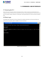
5. COMMAND LINE INTERFACE.......................................................................................... 236
5.1 Accessing the CLI ....................................................................................................................................236
5.2 Telnet Login ..............................................................................................................................................236
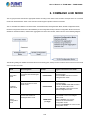
6. COMMAND LINE MODE ................................................................................................... 237
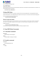
6.1 User EXEC Mode Commands..................................................................................................................239
6.1.1 broadcast command ..........................................................................................................................................239
6.1.2 enable command ...............................................................................................................................................239
6.1.3 logout command ................................................................................................................................................240
6.1.4 loopback Command...........................................................................................................................................240
6.1.5 ping command ...................................................................................................................................................240
6.1.6 tracert command................................................................................................................................................240
6.1.7 exit command ....................................................................................................................................................240
6.1.8 history command ...............................................................................................................................................241
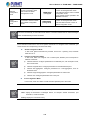
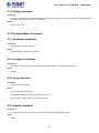
6.2 Privileged Mode Commands ...................................................................................................................241
6.2.1 broadcast command ..........................................................................................................................................241
6.2.2 configure command ...........................................................................................................................................241
6.2.3 copy command ..................................................................................................................................................241
6.2.4 disable command ..............................................................................................................................................241
6.2.5 firmware command ............................................................................................................................................242
6.2.6 logout command ................................................................................................................................................242
6.2.7 loopback Command...........................................................................................................................................242
6.2.8 ping command ...................................................................................................................................................242
6.2.9 reboot command................................................................................................................................................242
6.2.10 reset command................................................................................................................................................243
6.2.11 tracert command ..............................................................................................................................................243
6.2.12 Clear command ...............................................................................................................................................243
6.2.13 exit command ..................................................................................................................................................243
6.2.14 history command .............................................................................................................................................243
6.2.15 show command ...............................................................................................................................................244
6.3 Global Config Mode Commands.............................................................................................................245
6.3.1 access-list Command ........................................................................................................................................245
6.3.2 Contact-info Command......................................................................................................................................245
6.3.3 enable Command ..............................................................................................................................................245
6.3.4 hostname Command .........................................................................................................................................246
6.3.5 interface Command ...........................................................................................................................................246
6.3.6 ip Command ......................................................................................................................................................246
7
User’s Manual of FGSW-2840 / FGSW-4840S
6.3.7 lacp Command ..................................................................................................................................................247
6.3.8 location Command.............................................................................................................................................247
6.3.9 logging Command .............................................................................................................................................247
6.3.10 loopback-detection Command .........................................................................................................................248
6.3.11 mac Command.................................................................................................................................................248
6.3.12 monitor Command ...........................................................................................................................................248
6.3.13 port-channel Command ...................................................................................................................................249
6.3.14 qos Command .................................................................................................................................................249
6.3.15 rmon Command ...............................................................................................................................................249
6.3.16 snmp-server Command ...................................................................................................................................250
6.3.17 spanning tree Command .................................................................................................................................251
6.3.18 system-time Command....................................................................................................................................252
6.3.19 user Command ................................................................................................................................................252
6.3.20 vlan Command ................................................................................................................................................253
6.3.21 voice Command...............................................................................................................................................253
6.3.22 clear Command ...............................................................................................................................................254
6.3.23 end Command .................................................................................................................................................254
6.3.24 exit Command .................................................................................................................................................254
6.3.25 history Command ............................................................................................................................................254
6.3.26 show Command...............................................................................................................................................255
7. SWITCH OPERATION ....................................................................................................... 256
7.1 Address Table ...........................................................................................................................................256
7.2 Learning ....................................................................................................................................................256
7.3 Forwarding & Filtering .............................................................................................................................256
7.4 Store-and-Forward ...................................................................................................................................256
7.5 Auto-Negotiation ......................................................................................................................................257
8. TROUBLESHOOTING....................................................................................................... 258
APPENDIX A ......................................................................................................................... 260
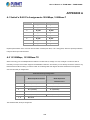
A.1 Switch's RJ45 Pin Assignments 1000Mbps, 1000Base-T ....................................................................260
A.2 10/100Mbps, 10/100Base-TX ...................................................................................................................260
8
User’s Manual of FGSW-2840 / FGSW-4840S
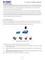
1. INTRODUCTION
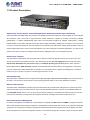
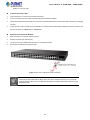
Thank you for purchasing PLANET 24 / 48-Port 10/100TX + 4-Port Gigabit Managed Switch, FGSW-2840/FGSW-4840S. The
descriptions of these two models are shown below:
FGSW-2840
24-Port 10/100TX + 4-Port Gigabit with 2 Combo 100/1000X SFP Managed Switch
FGSW-4840S
48-Port 10/100TX + 2-Port Gigabit + 2-Port 1000X SFP Managed Switch
“Managed Switch” mentioned in this quick installation guide refers to the FGSW-2840 and FGSW-4840S.
1.1 Package Contents
Open the box of the Managed Switch and carefully unpack it. The box should contain the following items:
The FGSW-2840 or FGSW-4840S x 1 (With SFP Dust Cap x 2)
Quick Installation Guide x 1
Power Cord x 1
Rubber Feet x 4
Two 19” Rack-mounting Brackets Kit x 1
If any of these are missing or damaged, please contact your dealer immediately; if possible, retain the carton including the
original packing material, and use them again to repack the product in case there is a need to return it to us for repair.
9
User’s Manual of FGSW-2840 / FGSW-4840S
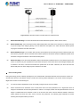
1.2 Product Description
High-Density, Full-Functioned, Layer 2 Managed Switch for Enterprise and Campus Networking
The FGSW-2840 and FGSW-4840S is a 24/48-Port 10/100Mbps Fast Ethernet Switch with 2/4-Port Gigabit and 2-Port Gigabit
SFP interfaces, which comes with a high-performance switch architecture, capable of providing non-blocking 12.8Gbps
(FGSW-2840) / 17.6Gbps (FGSW-4840S) switch fabric and wire-speed throughput at 9.5Mpps (FGSW-2840) / 13Mpps
(FGSW-4840S). Its four built-in GbE uplink ports also offer incredible extensibility, flexibility and connectivity to the core switch
or servers. The powerful features of QoS and network security offered by the FGSW-2840 / FGSW-4840S enable the switch to
perform effective data traffic control for ISP and enterprise VoIP, video streaming and multicast applications. It is ideal for the
remote access layer of campus or enterprise networks and the aggregation layer of IP metropolitan networks.
Robust Layer 2 Feature
The FGSW-2840 / FGSW-4840S can be programmed for advanced switch management functions such as port mirror, port
security, port isolation and loopback detection. It also features the dynamic port link aggregation (Static Trunk and LACP),
802.1Q VLAN, Rapid Spanning Tree protocol (RSTP) and Multiple Spanning Tree protocol (MSTP), Static / Dynamic /
Filtering MAC address, IGMP Snooping, Multicast IP and Multicast Filter and DHCP filtering. Via aggregation of supporting
ports, the FGSW-2840 / FGSW-4840S allow the operation of a high-speed trunk to combine with multiple ports. It enables a
maximum of up to 6 groups of 4 ports for trunk and supports fail-over as well.
Enhanced Security
The FGSW-2840 / FGSW-4840S offer comprehensive Layer 2 to Layer 4 Access Control List (ACL) for enforcing security to
the edge. It can be used to restrict network access by denying packets based on source and destination IP address.
Efficient Traffic Control
The FGSW-2840 / FGSW-4840S is loaded with robust QoS features and powerful traffic management to enhance services to
business-class data, voice, and video solutions. The functionality includes broadcast / multicast / unicast storm control, per
port bandwidth control, 802.1p / CoS / IP DSCP QoS priority and remarking. It guarantees the best performance at VoIP and
video stream transmission, and empowers the enterprises to take full advantages of the limited network resources.
Enhanced and Secure Management
For efficient management, the FGSW-2840 / FGSW-4840S are equipped with Web, Telnet and SNMP management interfaces.
With the built-in Web-based management interface, the FGSW-2840 / FGSW-4840S offer an easy-to-use, platform-independent
management and configuration facility. By supporting the standard Simple Network Management Protocol (SNMP), the switch
can be managed via any standard management software. For text-based management, the switch can be accessed via Telnet .
10
User’s Manual of FGSW-2840 / FGSW-4840S
Moreover, the FGSW-2840 / FGSW-4840S offers secure remote management by supporting HTTPS and SNMPv3 connections
which encrypt the packet content at each session.
Flexible Extension Solution
The two mini-GBIC slots built in the FGSW-2840 / FGSW-4840S are compatible with the 1000Base-SX/LX SFP (Small
Form-factor Pluggable) fiber transceiver to uplink to the backbone switch and monitoring center in long distance. The distance
can be extended from 550 meters (multi-mode fiber) to 10/20/30/40/50/60/70/120 kilometers (single-mode fiber or WDM fiber).
They are well suited for applications within the enterprise data centers and distributions, the two mini-GBIC slots built in the
FGSW-2840 also compatible with 100Base-FX SFP fiber transceiver.
1.3 How to Use This Manual
This User Manual is structured as follows:
Section 2 INSTALLATION
The section explains the functions of the Managed Switch and how to physically install the Managed Switch.
Section 3 SWITCH MANAGEMENT
The section contains the information about the software function of the Managed Switch.
Section 4 WEB CONFIGURATION
The section explains how to manage the Managed Switch by Web interface.
Section 5 COMMAND LINE INTERFACE
The section describes how to use the Command Line interface (CLI).
Section 6 COMMAND LINE MODE
The section explains how to manage the Managed Switch by Command Line interface.
Section 7 SWITCH OPERATION
The chapter explains how to do the switch operation of the Managed Switch.
Section 8 TROUBLESHOOTING
The chapter explains how to troubleshoot the Managed Switch.
Appendix A
The section contains cable information of the Managed Switch.
11
User’s Manual of FGSW-2840 / FGSW-4840S
1.4 Product Features
Physical Port (FGSW-2840)
■ 24-port 10/100Base-TX Fast Ethernet RJ45 copper, auto MDI / MDIX
■ 4-port 10/100/1000Base-T Gigabit Ethernet RJ45 copper, auto MDI / MDIX
■ 2 Combo 100/1000Base-X mini-GBIC/SFP slots (Share with Port 27/28)
■ Reset button for system factory default
Physical Port (FGSW-4840S)
■ 48-port 10/100Base-TX Fast Ethernet RJ45 copper, auto MDI / MDIX
■ 2-port 10/100/1000Base-T Gigabit Ethernet RJ45 copper, auto MDI / MDIX
■ 2 1000Base-X mini-GBIC/SFP slots
■ Reset button for system factory default
Layer 2 Features
■ Prevents packet loss with back pressure (half-duplex) and IEEE 802.3x pause frame flow control (full-duplex)
■ High-performance Store and Forward architecture, and runt/CRC filtering eliminates erroneous packets to optimize
the network bandwidth
■ Supports VLAN
-
IEEE 802.1Q tagged VLAN, up to 512VLAN groups, out of 4094 VLAN IDs
-
Management VLAN
■ Supports Spanning Tree Protocol
-
STP (Spanning Tree Protocol)
-
RSTP (Rapid Spanning Tree Protocol)
-
MSTP (Multiple Spanning Tree Protocol)
-
Loop Guard, Root Guard, TC, BPDU Guard, STP BPDU Guard, BPDU Filtering
■ Supports Link Aggregation
IEEE 802.3ad Link Aggregation Control Protocol (LACP)
Cisco ether-channel (Static Trunk)
Maximum 6 trunk groups, up to 4 ports per trunk group
■ Provides port mirror (many-to-1)
Quality of Service
■ Ingress / Egress Rate Limit per port bandwidth control
■ Storm Control support
Broadcast / Unknown Unicast / Unknown Multicast
■ Traffic classification
-
IEEE 802.1p CoS
-
DSCP / ToS priority
■ Strict priority, Weighted Round Robin (WRR) and Equal CoS policies
■ Voice VLAN
12
User’s Manual of FGSW-2840 / FGSW-4840S
Multicast
■ IGMP Snooping v1, v2 and v3
■ Multicast IP Table / Static Multicast IP
■ Multicast Filter
Security
■ L2 / L3 / L4 Access Control List
■ MAC Security
Static MAC
MAC Filtering
■ Port Security for Source MAC address entries filtering
■ Port Isolation, loopback detection
■ DHCP Filtering
Management
■ Switch Management Interface
-
Web switch management
Telnet Command Line Interface
SNMP v1, v2c and v3
-
SSL v2, v3 / SSH v1,v2 secure access
-
IP / MAC / Port-based Web access control
■ Static, DHCP and BooTP for IP address assignment
■ System Maintenance
-
Firmware upload / download via HTTP
Configuration upload / download through HTTP
Hardware reset button for system reset to factory default
System CPU / Memory status monitor
■ System Time Setting
-
Manual Setting
Network Time Protocol
PC clock synchronization
■ Daylight Saving Time Setting
■ SNMP trap for interface Link Up and Link Down notification
■ System Local Log / remote log / backup log
■ Four RMON groups (history, statistics, alarms and events)
■ Virtual Cable Test / Loop Back Test
13
User’s Manual of FGSW-2840 / FGSW-4840S
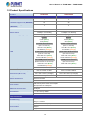
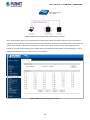
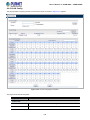
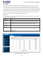
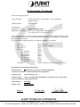
1.5 Product Specifications
Product
FGSW-2840
FGSW-4840S
Hardware Version
1
3
10/100TX Copper Ports (MDI/MDIX)
24
48
4
2
2 100/1000Base-X SFP interfaces
2 1000Base-X SFP interfaces
12.8Gbps / non-blocking
17.6Gbps / non-blocking
9.5Mpps @64 bytes
13Mpps @64 bytes
Hardware Specifications
10/100/1000T Copper Ports
(MDI/MDIX)
SFP/mini-GBIC Slots
Switch Fabric
Switch Throughput@64 bytes
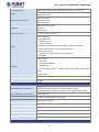
LED
System:
System:
Power (Green)
Power (Green)
SYS (Green)
SYS (Green)
10/100TX RJ45 Interfaces
10/100TX RJ45 Interfaces
(Port 1 to Port 24):
(Port 1 to Port 48):
100 LNK / ACT (Green)
100 LNK / ACT (Green)
10 LNK/ACT (Orange)
10 LNK/ACT (Orange)
10/100/1000T RJ45 Interfaces
10/100/1000T RJ45 Interfaces
(Port 25 to Port 28):
(Port 49 to Port 50):
1000 LNK / ACT (Green)
1000 LNK / ACT (Green)
10/100 LNK/ACT (Orange)
10/100 LNK/ACT (Orange)
100/1000Mbps SFP Interfaces
1000Mbps SFP Interfaces
(Share with Port 27 to Port 28):
1000 LNK / ACT (Green)
(Port 51 to Port 52):
1000 LNK / ACT (Green)
100 LNK/ACT (Orange)
Power Requirements
Power Consumption / Dissipation
Dimensions (W x D x H)
100~240V AC, 50/60Hz, 0.6A
100~240V AC, 50/60Hz, 0.4A
Max 12.8 watts / 43 BTU
Max.17.3 watts / 59BTU
440 x 180 x 44mm (1U height)
440 x 180 x 44mm (1U height)
1.9kg
2.5kg
Weight
Switch Architecture
Store-and-Forward
MAC Address Table
8K entries
Flow Control
Maximum Transmit Unit
Reset Button
Enclosure
IEEE 802.3x pause frame for full-duplex
Back pressure for half-duplex
9216bytes
> 5 sec: Factory default
Metal
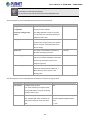
Layer 2 Functions
Port Mirroring
TX / RX
Many-to-1 monitor
Port Security
up to 64 MAC Address per port
Port Isolation
Support
Loopback Detection
Support
14
User’s Manual of FGSW-2840 / FGSW-4840S
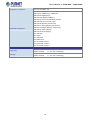
Link Aggregation
VLAN
IEEE 802.3ad LACP and static trunk supports 6 groups of 4-port trunk.
802.1Q tagged-based VLAN, up to 512 VLAN groups, out of 4094 VLAN IDs
Management VLAN
IEEE 802.1D STP
Spanning Tree Protocol
IEEE 802.1w RSTP
IEEE 802.1s MSTP
IGMP (v1/v2/v3) Snooping
Multicast
Multicast IP
Multicast Filter
Access Control List
L2 / L3 / L4 Access Control List
4 Priority Queues
Traffic classification:
- IEEE 802.1p CoS
- DSCP / ToS priority
QoS
Strict priority, Weighted Round Robin (WRR) and Equal CoS policies
Ingress / Egress Rate Limit per port bandwidth control
Storm Control support:
- Broadcast / Unknown Unicast / Unknown Multicast
Voice VLAN
MAC Security:
- Static MAC
- Dynamic MAC address
Security
- MAC Filtering
Loop Guard, Root Guard, TC, BPDU Guard, STP BPDU Guard, BPDU
Filtering,
DHCP Filtering
Virtual Cable Test
Support
Loopback Test
Support
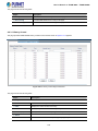
Management Functions
Web browser / Telnet / SNMP v1, v2c, v3 / SSL v2, v3 / SSH v1,v2
Basic Management Interfaces
Firmware upgrade by HTTP protocol through Ethernet network
Configuration Backup / Restore by HTTP protocol through Ethernet network
Secure Management Interfaces
HTTPs, SNMP v3
Web Access Control
IP / MAC / Port-based Web access control
System IP Address Assignment
Static, DHCP and BooTP
System Log
System local log / remote log / backup log
System Time Setting
Manual Setting, Network Time Protocol, PC clock synchronization
Daylight Saving Time
Support
SNMP RMON
RFC 2819 RMON (1, 2, 3, 9)
SNMP Trap
Interface Link Up and Link Down notification
Standards Conformance
15
User’s Manual of FGSW-2840 / FGSW-4840S
Regulation Compliance
FCC Part 15 Class A, CE
IEEE 802.3 10Base-T
IEEE 802.3u 100Base-TX / 100Base-FX
IEEE 802.3z Gigabit SX/LX
IEEE 802.3ab Gigabit 1000Base-T
IEEE 802.3x Flow Control and Back pressure
IEEE 802.3ad Port Trunk with LACP
IEEE 802.1D Spanning Tree protocol
IEEE 802.1w Rapid Spanning Tree protocol
Standards Compliance
IEEE 802.1s Multiple Spanning Tree protocol
IEEE 802.1p Class of Service
IEEE 802.1Q VLAN Tagging
RFC 768 UDP
RFC 791 IP
RFC 792 ICMP
RFC 2068 HTTP
RFC 1112 IGMP version 1
RFC 2236 IGMP version 2
RFC 3376 IGMP version 3
Environment
Operating
Temperature:
Relative Humidity:
0 ~ 50 degrees C
5 ~ 95% (non-condensing)
Storage
Temperature:
Relative Humidity:
-10 ~ 70 degrees C
5 ~ 95% (non-condensing)
16
User’s Manual of FGSW-2840 / FGSW-4840S
2. INSTALLATION
This section describes the hardware features and installation of the Managed Switch on the desktop or rack mount. For easier
management and control of the Managed Switch, familiarize yourself with its display indicators, and ports. Front panel
illustrations in this chapter display the unit LED indicators. Before connecting any network device to the Managed Switch, please
read this chapter completely.
2.1 Hardware Description
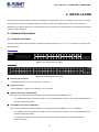
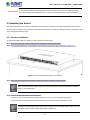
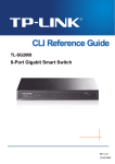
2.1.1 Switch Front Panel
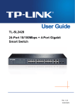
The front panel provides a simple interface monitoring the Managed Switch. Figure 2-1-1 & 2-1-2 shows the front panel of the
Managed Switch.
Front Panel
Figure 2-1-1: FGSW-2840 Front Panel
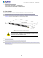
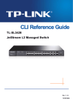
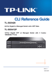
Front Panel
Figure 2-1-2: FGSW-4840S Front Panel
■ Fast Ethernet TP Interface
10/100Base-TX Copper, RJ-45 Twist-Pair: Up to 100 meters.
■ Gigabit TP Interface
10/100/1000Base-T Copper, RJ-45 Twist-Pair: Up to 100 meters.
■ 1000Base-X SFP Slots (FGSW-4840S)
Each of the SFP (Small Form-factor Pluggable) slot supports Dual-speed, 1000Base-SX / LX.
-
For 1000Base-SX/LX SFP transceiver module: From 550 meters (Multi-mode fiber), up to 10/20/30/40/50/60/70/120
kilometers (Single-mode fiber).
■ 100/1000Base-X SFP Slots (FGSW-2840)
Each of the SFP (Small Form-factor Pluggable) slot supports Dual-speed, 1000Base-SX / LX or 100Base-FX.
-
For 1000Base-SX/LX SFP transceiver module: From 550 meters (Multi-mode fiber), up to 10/20/30/40/50/60/70/120
kilometers (Single-mode fiber).
-
For 100Base-FX SFP transceiver module: From 2 kilometers (Multi-mode fiber), up to 20/40/60 kilometers
(Single-mode fiber).
17
User’s Manual of FGSW-2840 / FGSW-4840S
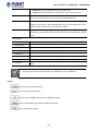
■ Reset Button
At front panel of Managed Switch, the reset button is designed for reboot the Managed Switch without turn off and on the
power. The following is the summary table of Reset button function:
Reset Button Pressed and Released
Function
Reset the Managed Switch to Factory Default configuration.
The Managed Switch will then reboot and load the default
settings as below:
> 5 seconds: Factory Default
。
Default Username: admin
。
Default Password: admin
。
Default IP address: 192.168.0.100
。
Subnet mask: 255.255.255.0
。
Default Gateway: 192.168.0.254
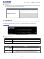
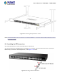
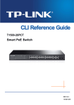
2.1.2 LED Indications
The front panel LEDs indicates instant status of port links, data activity, system power and system CPU status; helps monitor
and troubleshoot when needed. Figure 2-1-3 & Figure 2-1-4 shows the LED indications of the Managed Switch.
LED Indication
Figure 2-1-3: FGSW-2840 LED Panel
■ FGSW-2840 LED Definition
System
LED
Color
Function
PWR
Green
Lights to indicate that the Switch has power.
SYS
Green
Lights and blinking to indicate the CPU is working.
10/100Base-TX Interfaces (Port 1 to port 24)
LED
Color
100
LNK/ACT
Green
10
LNK/ACT
Orange
Function
Lights: To indicate the link through that port is successfully established at 100Mbps.
Blink:
To indicate that the Switch is actively sending or receiving data over that port.
Lights: To indicate the link through that port is successfully established at 10Mbps.
Blink:
To indicate that the Switch is actively sending or receiving data over that port.
18
User’s Manual of FGSW-2840 / FGSW-4840S
■ 10/100/1000Base-T Interfaces (Port 25 to port 28)
LED
Color
1000
LNK/ACT
Green
10/100
LNK/ACT
Orange
Function
Lights: To indicate the link through that port is successfully established at 1000Mbps.
Blink:
To indicate that the Switch is actively sending or receiving data over that port.
Lights: To indicate the link through that port is successfully established at 10Mbps or 100Mbps.
Blink:
To indicate that the Switch is actively sending or receiving data over that port.
■ 1000Base-X SFP Interfaces (Share with Port 27 to port 28)
LED
Color
1000
LNK/ACT
Green
100
LNK/ACT
Orange
Function
Lights: To indicate the link through that port is successfully established at 1000Mbps.
Blink:
To indicate that the Switch is actively sending or receiving data over that port.
Lights: To indicate the link through that port is successfully established at 100Mbps.
Blink:
To indicate that the Switch is actively sending or receiving data over that port.
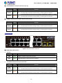
LED Indication
Figure 2-1-4: FGSW-4840S LED Panel
■ FGSW-4840S LED Definition
System
LED
Color
Function
PWR
Green
Lights to indicate that the Switch has power.
SYS
Green
Lights and blinking to indicate the CPU is working.
10/100Base-TX Interfaces (Port 1 to port 48)
LED
Color
100
LNK/ACT
Green
10
LNK/ACT
Orange
Function
Lights: To indicate the link through that port is successfully established at 100Mbps.
Blink:
To indicate that the Switch is actively sending or receiving data over that port.
Lights: To indicate the link through that port is successfully established at 10Mbps.
Blink:
To indicate that the Switch is actively sending or receiving data over that port.
19
User’s Manual of FGSW-2840 / FGSW-4840S
■ 10/100/1000Base-T Interfaces (Port 49 to port 50)
LED
Color
1000
LNK/ACT
Green
10/100
LNK/ACT
Orange
Function
Lights: To indicate the link through that port is successfully established at 1000Mbps.
Blink:
To indicate that the Switch is actively sending or receiving data over that port.
Lights: To indicate the link through that port is successfully established at 10Mbps or 100Mbps.
Blink:
To indicate that the Switch is actively sending or receiving data over that port.
■ 1000Base-X SFP Interfaces (Port 51 to port 52)
LED
Color
LNK/ACT
Green
Function
Lights: To indicate the link through that port is successfully established at 1000Mbps.
Blink:
To indicate that the Switch is actively sending or receiving data over that port.
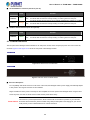
2.1.3 Switch Rear Panel
The rear panel of the Managed Switch indicates an AC inlet power socket, which accepts input power from 100 to 240V AC,
50-60Hz. Figure 2-1-5 & Figure 2-1-6 shows the rear panel of this Managed Switch.
Rear Panel
Figure 2-1-5: Rear Panel of FGSW-2840
Rear Panel
Figure 2-1-6: Rear Panel of FGSW-4840S
■ AC Power Receptacle
For compatibility with electric service in most areas of the world, the Managed Switch’s power supply automatically adjusts
to line power in the range of 100-240V AC and 50/60Hz.
Plug the female end of the power cord firmly into the receptalbe on the rear panel of the Managed Switch. Plug the other
end of the power cord into an electric service outlet and the power will be ready.
The device is a power-required device, which means it will not work till it is powered. If your networks
Power Notice: should be active all the time, please consider using UPS (Uninterrupted Power Supply) for your device.
It will prevent you from network data loss or network downtime.
20
User’s Manual of FGSW-2840 / FGSW-4840S
Power Notice:
In some areas, installing a surge suppression device may also help to protect your Managed Switch
from being damaged by unregulated surge or current to the Managed Switch or the power adapter.
2.2 Installing the Switch
This section describes how to install your Managed Switch and make connections to the Managed Switch. Please read the
following topics and perform the procedures in the order being presented. To install your Managed Switch on a desktop or shelf,
simply complete the following steps.
2.2.1 Desktop Installation
To install the Managed Switch on desktop or shelf, please follow these steps:
Step1: Attach the rubber feet to the recessed areas on the bottom of the Managed Switch.
Step2: Place the Managed Switch on the desktop or the shelf near an AC power source, as shown in Figure 2-1-7.
Figure 2-1-7: Place the Managed Switch on the desktop
Step3: Keep enough ventilation space between the Managed Switch and the surrounding objects.
When choosing a location, please keep in mind the environmental restrictions discussed in Chapter 1,
Section 4, and specifications.
Step4: Connect the Managed Switch to network devices.
Connect one end of a standard network cable to the RJ-45 ports on the front of the Managed Switch.
Connect the other end of the cable to the network devices such as printer server, workstation or router.
Connection to the Managed Switch requires UTP Category 5 network cabling with RJ-45 tips. For more
information, please see the Cabling Specification in Appendix A.
21
User’s Manual of FGSW-2840 / FGSW-4840S
Step5: Supply power to the Managed Switch.
Connect one end of the power cable to the Managed Switch.
Connect the power plug of the power cable to a standard wall outlet.
When the Managed Switch receives power, the Power LED should remain solid Green.
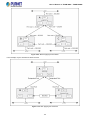
2.2.2 Rack Mounting
To install the Managed Switch in a 19-inch standard rack, please follow the instructions described below.
Step1: Place the Managed Switch on a hard flat surface, with the front panel positioned towards the front side.
Step2: Attach the rack-mount bracket to each side of the Managed Switch with supplied screws attached to the package.
Figure 2-1-8 shows how to attach brackets to one side of the Managed Switch.
Figure 2-1-8: Attach Brackets to the Managed Switch
You must use the screws supplied with the mounting brackets. Damage caused to the parts by
using incorrect screws would invalidate the warranty.
Step3: Secure the brackets tightly.
Step4: Follow the same steps to attach the second bracket to the opposite side.
Step5: After the brackets are attached to the Managed Switch, use suitable screws to securely attach the brackets to the rack,
as shown in Figure 2-1-9.
22
User’s Manual of FGSW-2840 / FGSW-4840S
Figure 2-1-9: Mounting Managed Switch in a Rack
Step6: Proceeds with Steps 4 and 5 of session 2.2.1 Desktop Installation to connect the network cabling and supply power to
the Managed Switch.
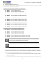
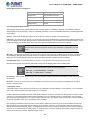
2.2.3 Installing the SFP transceiver
The sections describe how to insert an SFP transceiver into an SFP slot.
The SFP transceivers are hot-pluggable and hot-swappable. You can plug in and out the transceiver to/from any SFP port
without having to power down the Managed Switch, as the Figure 2-1-10 shows.
Figure 2-1-10: Plug In the SFP Transceiver
23
User’s Manual of FGSW-2840 / FGSW-4840S
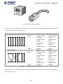
Approved PLANET SFP Transceivers
PLANET Managed Switch supports both Single mode and Multi-mode SFP transceiver. The following list of approved PLANET
SFP transceivers is correct at the time of publication:
Gigabit SFP Transceiver Modules (FGSW-2840 / FGSW-4840S)
MGB-GT
SFP-Port 1000Base-T Module
MGB-SX
SFP-Port 1000Base-SX mini-GBIC module
MGB-LX
SFP-Port 1000Base-LX mini-GBIC module -10KM
MGB-L30
SFP-Port 1000Base-LX mini-GBIC module -30KM
MGB-L50
SFP-Port 1000Base-LX mini-GBIC module -50KM
MGB-L70
SFP-Port 1000Base-LX mini-GBIC module -70KM
MGB-L120
SFP-Port 1000Base-LX mini-GBIC module -120KM
MGB-LA10
SFP-Port 1000Base-LX (WDM,TX:1310nm) -10KM
MGB-LB10
SFP-Port 1000Base-LX (WDM,TX:1550nm) -10KM
MGB-LA20
SFP-Port 1000Base-LX (WDM,TX:1310nm) -20KM
MGB-LB20
SFP-Port 1000Base-LX (WDM,TX:1550nm) -20KM
MGB-LA40
SFP-Port 1000Base-LX (WDM,TX:1310nm) -40KM
MGB-LB40
SFP-Port 1000Base-LX (WDM,TX:1550nm) -40KM
Fast Ethernet SFP Transceiver Modules (FGSW-2840 only)
MFB-FX
SFP-Port 100Base-FX Transceiver -2KM
MFB-F20
SFP-Port 100Base-FX Transceiver -20KM
MFB-F40
SFP-Port 100Base-FX Transceiver -40KM
MFB-F60
SFP-Port 100Base-FX Transceiver -60KM
MFB-FA20
SFP-Port 100Base-BX Transceiver (WDM,TX:1310nm) -20KM
MFB-FB20
SFP-Port 100Base-BX Transceiver (WDM,TX:1550nm) -20KM
It is recommended to use PLANET SFP on the Managed Switch. If you insert an SFP transceiver
that is not supported, the Managed Switch will not recognize it.
In the installation steps below, this Manual uses Gigabit SFP transceiver as an example. However,
the steps for Fast Ethernet SFP transceiver are similar.
1.
Before we connect Managed Switch to the other network device, we have to make sure both sides of the SFP
transceivers are with the same media type, for example: 1000Base-SX to 1000Base-SX, 1000Bas-LX to 1000Base-LX.
2.
Check whether the fiber-optic cable type matches with the SFP transceiver requirement.
To connect to 1000Base-SX SFP transceiver, please use the multi-mode fiber cable with one side being the male
duplex LC connector type.
To connect to 1000Base-LX SFP transceiver, please use the single-mode fiber cable with one side being the male
24
User’s Manual of FGSW-2840 / FGSW-4840S
duplex LC connector type.
Connect the Fiber Cable
1.
Insert the duplex LC connector into the SFP transceiver.
2.
Connect the other end of the cable to a device with SFP transceiver installed.
3.
Check the LNK/ACT LED of the SFP slot on the front of the Managed Switch. Ensure that the SFP transceiver is operating
correctly.
4.
Check the Link mode of the SFP port if the link fails. To function with some fiber-NICs or Media Converters, user has to set
the port Link mode to “1000 Force” or “100 Force”.
Remove the Transceiver Module
1.
Make sure there is no network activity anymore.
2.
Remove the Fiber-Optic Cable gently.
3.
Lift up the lever of the MGB module and turn it to a horizontal position.
4.
Pull out the module gently through the lever.
Figure 2-1-11: How to Pull Out the SFP Transceiver
Never pull out the module without lifting up the lever of the module and turning it to a horizontal
position. Directly pulling out the module could damage the module and the SFP module slot of the
Managed Switch.
25
User’s Manual of FGSW-2840 / FGSW-4840S
3. SWITCH MANAGEMENT
This chapter explains the methods that you can use to configure management access to the Managed Switch. It describes the
types of management applications and the communication and management protocols that deliver data between your
management device (workstation or personal computer) and the system. It also contains information about port connection
options.
This chapter covers the following topics:
Requirements
Management Access Overview
Web Management Access
SNMP Access
3.1 Requirements
Workstations running Windows 2000/XP, 2003, Vista/7/8, 2008, MAC OS9 or later, Linux, UNIX or other platforms
are compatible with TCP/IP protocols.
Workstation is installed with Ethernet NIC (Network Interface Card)
Ethernet Port connection
Network cables -- Use standard network (UTP) cables with RJ45 connectors.
The above Workstation is installed with WEB Browser and JAVA runtime environment Plug-in
It is recommended to use Internet Explore 8.0 or above to access the Managed Switch. If the Web
interface of the Managed Switch is not accessible, please turn off the anti-virus software or firewall
and then try it again.
26
User’s Manual of FGSW-2840 / FGSW-4840S
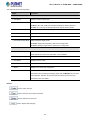
3.2 Management Access Overview
The Managed Switch gives you the flexibility to access and manage it using any or all of the following methods:
Web browser interface
An external SNMP-based network management application
The administration Web browser interface supports are embedded in the Managed Switch software and are available for
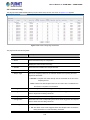
immediate use. Each of these management methods has their own advantages. Table 3-1 compares the three management
methods.
Method
Advantages
Disadvantages
Web Browser
Ideal for configuring the switch remotely
Compatible with all popular browsers
Security can be compromised (hackers need
only know the IP address and subnet mask)
Can be accessed from any location
May encounter lag times on poor connections
Most visually appealing
SNMP Agent
Communicates with switch functions at
Requires SNMP manager software
Least visually appealing of all three methods
the MIB level
Based on open standards
Some settings require calculations
Security can be compromised (hackers need
only know the community name)
Table 3-1: Comparison of Management Methods
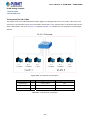
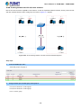
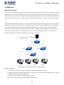
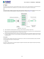
3.3 Web Management
The Managed Switch offers management features that allow users to manage the Managed Switch from anywhere on the
network through a standard browser such as Microsoft Internet Explorer. After you set up your IP address for the Managed
Switch, you can access the Managed Switch’s Web interface applications directly in your Web browser by entering the IP
address of the Managed Switch.
Figure 3-1: Web Management
You can then use your Web browser to list and manage the Managed Switch configuration parameters from one central location;
Web Management requires Microsoft Internet Explorer 8.0 or later, Google Chrome, Safari or Mozilla Firefox 1.5 or later.
27
User’s Manual of FGSW-2840 / FGSW-4840S
The following web screen based on FGSW-4840S, for FGSW-2840 the display will be the same
to FGSW-4840S.
Figure 3-2: Web Main Screen of Managed Switch
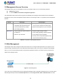
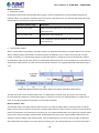
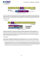
3.4 SNMP-Based Network Management
You can use an external SNMP-based application to configure and manage the Managed Switch, such as SNMPc Network
Manager, HP Openview Network Node Management (NNM) or What’s Up Gold. This management method requires the SNMP
agent on the switch and the SNMP Network Management Station to use the same community string. This management
method, in fact, uses two community strings: the get community string and the set community string. If the SNMP Network
management Station only knows the set community string, it can read and write to the MIBs. However, if it only knows the get
community string, it can only read MIBs. The default gets and sets community strings for the Managed Switch are public.
Figure 3-3: SNMP Management
28
User’s Manual of FGSW-2840 / FGSW-4840S
4. WEB CONFIGURATION
This section introduces the configuration and functions of the Web-based management.
About Web-based Management
The Managed Switch offers management features that allow users to manage the Managed Switch from anywhere on the
network through a standard browser such as Microsoft Internet Explorer.
The Web-based Management supports Internet Explorer 8.0. It is based on Java Applets with an aim to reduce network
bandwidth consumption, enhance access speed and present an easy viewing screen.
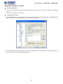
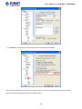
By default, IE8.0 or later version does not allow Java Applets to open sockets. The user has to
explicitly modify the browser setting to enable Java Applets to use network ports.
The following web screen based on FGSW-4840S, for FGSW-2840 the display will be the same
to FGSW-4840S.
The Managed Switch can be configured through an Ethernet connection, making sure the manager PC must be set on the same
IP subnet address as the Managed Switch.
For example, the default IP address of the Managed Switch is 192.168.0.100, then the manager PC should be set at
192.168.0.x (where x is a number between 1 and 254, except 100), and the default subnet mask is 255.255.255.0.
If you have changed the default IP address of the Managed Switch to 192.168.1.1 with subnet mask 255.255.255.0 via web,
then the manager PC should be set at 192.168.1.x (where x is a number between 2 and 254) to do the relative configuration on
manager PC.
Figure 4-1-1: Web Management
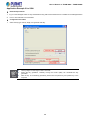
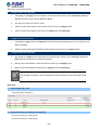
1.
Logging on the Managed Switch
Use Internet Explorer 8.0 or above Web browser. Enter the factory-default IP address to access the Web interface. The
factory-default IP Address as following:
29
User’s Manual of FGSW-2840 / FGSW-4840S
http://192.168.0.100
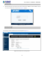
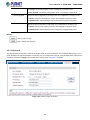
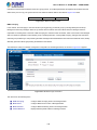
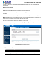
2.
When the following login screen appears, please enter the default username "admin" with password “admin” to login the
main screen of Managed Switch. The login screen in Figure 4-1-2 appears.
Figure 4-1-2: Login Screen
Default User name: admin
Default Password: admin
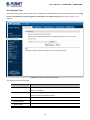
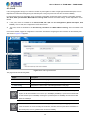
After entering the username and password, the main screen appears as Figure 4-1-3.
Figure 4-1-3: Web Main Screen of Managed Switch
30
User’s Manual of FGSW-2840 / FGSW-4840S
Now, you can use the Web management interface to continue the switch management or manage the Managed Switch by Web
interface. The Switch Menu on the left of the web page let you access all the commands and statistics the Managed Switch
provides.
It is recommended to use Internet Explore 8.0 or above to access Managed Switch.
The changed IP address takes effect immediately after clicking on the Apply button. You need
to use the new IP address to access the Web interface.
For security reason, please change and memorize the new password after this first setup.
Only accept command in lowercase letter under web interface.
31
User’s Manual of FGSW-2840 / FGSW-4840S
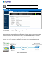
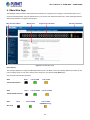
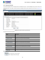
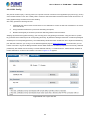
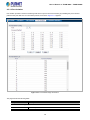
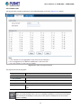
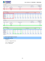
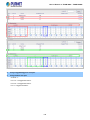
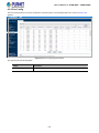
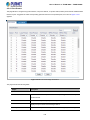
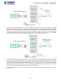
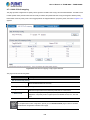
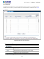
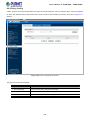
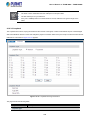
4.1 Main Web Page
The Managed Switch provides a Web-based browser interface for configuring and managing it. This interface allows you to
access the Managed Switch using the Web browser of your choice. This chapter describes how to use the Managed Switch’s
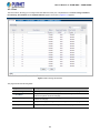
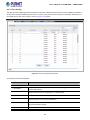
Web browser interface to configure and manage it.
Main Functions Menu
Main Screen
Copper Port Link Status
SFP Port Link Status
Figure 4-1-4: Web Main Page
Panel Display
The web agent displays an image of the Managed Switch’s ports. The Mode can be set to display different information for the
ports, including Link up or Link down. Clicking on the image of a port opens the Port Status page.
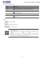
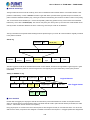
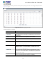
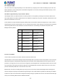
The port states are illustrated as follows:
State
Down
Link at 100M
Link at 10M
10/100TX RJ-45 Ports
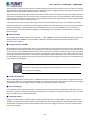
State
Down
Link at 1000M
Link at 10/100M
10/100/1000TRJ-45 Ports
State
Down
Link at 1000M
Link at 100M
(FGSW-2840 only)
SFP Ports
32
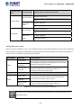
User’s Manual of FGSW-2840 / FGSW-4840S
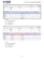
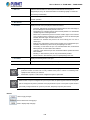
Main Menu
Using the onboard web agent, you can define system parameters, manage and control the Managed Switch and all its ports, or
monitor network conditions. Via the Web-Management, the administrator can set up the Managed Switch by selecting the
functions listed in the Main Function. The screen in Figure 4-1-5 appears.
Figure 4-1-5: Managed Switch Main Functions Menu
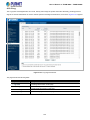
33
User’s Manual of FGSW-2840 / FGSW-4840S
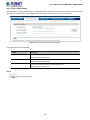
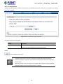
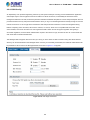
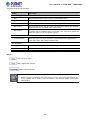
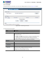
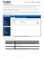
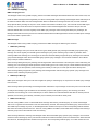
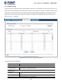
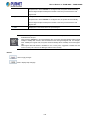
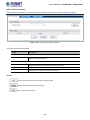
4.2 System
Use the System menu items to display and configure basic administrative details of the Managed Switch. Under System, the
following topics are provided to configure and view the system information. This section has the following items:
■ System Information
The switch system information is provided here.
■ User Management
Configure the switch management interface access authority on this page.
■ System Tools
The system tools provided here to configure related options.
■ Access Security
Configure system access security function on this page.
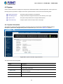
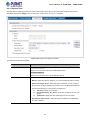
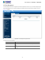
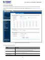
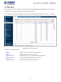
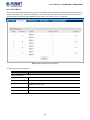
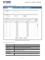
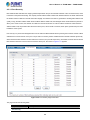
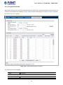
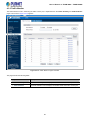
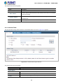
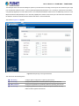
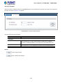
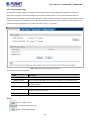
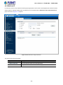
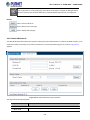
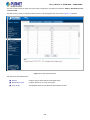
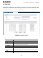
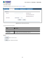
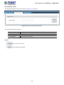
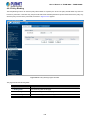
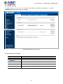
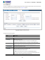
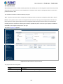
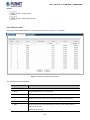
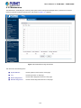
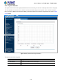
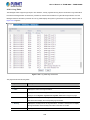
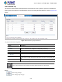
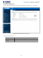
4.2.1 System Information
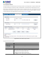
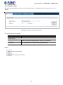
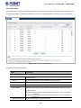
The System Info page provides basic properties configuration that can be implemented on System Summary, Device
Description, System Time, Daylight Saving Time and System IP pages. The screen in Figure 4-2-1 appears.
Figure 4-2-1: System Information Page Screenshot
The page includes the following fields:
Object
Description
System Summary
View the port connection status and the system information on this page.
Device Description
Configure the description of the switch, including device name, device location and
system contact on this page.
Configure the system time and the settings here will be used for other time-based
functions on this page.
System Time
Daylight Saving Time
Configure the Daylight Saving Time of the switch on this page.
System IP
Configure the system IP of the switch on this page.
34
User’s Manual of FGSW-2840 / FGSW-4840S
4.2.1.1 System Summary
The port status diagram shows the working status of 10/100Mbps RJ45 ports, 10/100/1000Mbps RJ45 ports and 2 SFP ports of
the Managed Switch, the System Summary includes the Managed Switch system information and the screen in Figure 4-2-2
appears.
Figure 4-2-2: System Summary Page Screenshot
The page includes the following fields:
Object
Description
System Description
Displays the current system description information.
Device Name
Displays the current system name information.
Device Location
Displays the current device location information.
System Contact
Displays the current system contact information.
Hardware Version
Displays the current hardware version information.
Firmware Version
Displays the current firmware version information.
IP Address
Displays the current IP address information.
Subnet Mask
Displays the current IP subnet mask address information.
Default Gateway
Displays the current IP default gateway information.
MAC Address
Displays the current MAC address information.
System Time
Displays the current system time information.
Run Time
Displays the current system operation time information.
Buttons
: Click to refresh the current web page.
: Click to display the help web page.
35
User’s Manual of FGSW-2840 / FGSW-4840S
4.2.1.2 Device Description
This page allows configuring the description of the Managed Switch, including device name, device location and system contact.
After setup is completed, please press “Apply” button to take effect, and the screen in Figure 4-2-3 appears.
Figure 4-2-3: Device Description Page Screenshot
The page includes the following fields:
Object
Description
Device Name
The name identifying the Managed Switch.
Maximum length: 32 characters.
Device Location
The device location information of the Managed Switch.
Maximum length: 32 characters.
System Contact
The system contact information of the Managed Switch.
Maximum length: 32 characters.
Button
: Click to apply changes.
36
User’s Manual of FGSW-2840 / FGSW-4840S
4.2.1.3 System Time
This page allows configuring system time and the settings here will be used for other time-based functions. After setup is
completed, please press “Apply” button to take effect, and the screen in Figure 4-2-4 appears.
Figure 4-2-4: System Time Page Screenshot
The page includes the following fields:
Object
Description
Time Information
Current System Date:
Displays the current date and time of the Managed Switch.
Current Time Source:
Displays the current time source of the Managed Switch.
Time Config
To set time from the following methods.
Manual - When this option is selected, you can set the date and time manually.
Get Time from NTP Server - When this option is selected, you can configure
the time zone and the IP Address for the NTP Server. The Managed Switch will
get time automatically if it is connected to a NTP Server.
Time Zone: Select your local time.
Primary/Secondary NTP Server: Enter the IP Address for the NTP
Server.
Update Rate: Specify the rate of fetching time from NTP server.
Synchronize with PC Clock - When this option is selected, the administrator
PC clock is utilized.
37
User’s Manual of FGSW-2840 / FGSW-4840S
The system time will be restored to the default when the Managed Switch is restarted and you
need to reconfigure the system of the Managed Switch.
When Get Time from NTP Server is selected and no time server is configured, the Managed
Switch will get time from the time server of the Internet if it has connected to the Internet.
Buttons
: Click to apply changes.
: Click to refresh current web page.
: Click to display help web page.
4.2.1.4 Daylight Saving Time
The Daylight Saving Time Configuration screenin Figure 4-2-5 appears.
Figure 4-2-5: Daylight Saving Time Page Screenshot
The page includes the following fields:
Object
Description
DST Status
Enable or disable the DST.
Predefined Mode
Select a predefined DST configuration.
USA: Second Sunday in March, 02:00 ~ First Sunday in November, 02:00.
Australia: First Sunday in October, 02:00 ~ First Sunday in April, 03:00.
38
User’s Manual of FGSW-2840 / FGSW-4840S
Europe: Last Sunday in March, 01:00 ~ Last Sunday in October, 01:00.
New Zealand: Last Sunday in September, 02:00 ~ First Sunday in April, 03:00.
Recurring Mode
Specify the DST configuration in recurring mode. This configuration is recurring in use.
Offset: Specify the time adding in minutes when Daylight Saving Time comes.
Start/End Time: Select starting time and ending time of Daylight Saving Time.
Date Mode
Specify the DST configuration in Date mode. This configuration is recurring in use.
Offset: Specify the time adding in minutes when Daylight Saving Time comes.
Start/End Time: Select starting time and ending time of Daylight Saving Time.
Buttons
: Click to apply changes.
: Click to display help web page.
4.2.1.5 System IP
This page provides three modes to obtain an IP address: Static IP, DHCP and BOOTP. The IP address obtained using a new
mode will replace the original IP address. On this page you can configure the system IP of the Managed Switch. After setup is
completed, please press “Apply” button to take effect, and the screen in Figure 4-2-6 appears.
Figure 4-2-6: System IP Page Screenshot
39
User’s Manual of FGSW-2840 / FGSW-4840S
The page includes the following fields:
Object
Description
MAC Address
Displays MAC Address of the Managed Switch.
IP Address Mode
Select the mode to obtain IP Address for the Managed Switch.
Static IP: When this option is selected, you should enter IP Address, Subnet Mask and
Default Gateway manually.
DHCP: When this option is selected, the Managed Switch will obtain network
parameters from the DHCP Server.
BOOTP: When this option is selected, the Managed Switch will obtain network
parameters from the BOOTP Server.
Management VLAN
Enter the ID of management VLAN, the only VLAN through which you can get access to
the Managed Switch. By default VLAN1 owning all the ports is the Management VLAN and
you can access the Managed Switch via any port on the Managed Switch. However, if
another VLAN is created and set to be the Management VLAN, you may have to reconnect
the management station to a port that is a member of the Management VLAN.
IP Address
Enter the system IP of the Managed Switch.
The default system IP is 192.168.0.100.
Subnet Mask
Enter the subnet mask of the Managed Switch.
The default subnet mask is 255.255.255.0.
Gateway
Enter the default gateway of the Managed Switch.
The default gateway is 192.168.0.254.
Changing the IP address to a different IP segment will interrupt the network communication;
please keep the new IP address in the same IP segment with the local network.
The Managed Switch only possesses an IP address; the IP address configured will replace the
original IP address.
If the Managed Switch gets the IP address from DHCP server, you can see the configuration of
the Managed Switch in the DHCP server; if DHCP option is selected but no DHCP server exists
in the network, a few minutes later, the Managed Switch will restore the setting to the default.
If DHCP or BOOTP option is selected, the Managed Switch will get network parameters
dynamically from the Internet, which means that its IP address, subnet mask and default
gateway cannot be configured.
Buttons
: Click to apply changes.
: Click to display help web page.
40
User’s Manual of FGSW-2840 / FGSW-4840S
4.2.2 User Management
The User Management functions to configure the user name and password for users to log on to the Web management page
with a certain access level so as to protect the settings of the Managed Switch from being randomly changed; the screen in
Figure 4-2-7 appears.
Figure 4-2-7: User Management Page Screenshot
The page includes the following fields:
Object
Description
User Table
View the information about the current users of the Managed Switch on this
page.
User Config
Configure the access level of the user to log on to the Web management page on
this page.
41
User’s Manual of FGSW-2840 / FGSW-4840S
4.2.2.1 User Table
This page provides view the information about the current users of the Managed Switch; the screen in Figure 4-2-8 appears.
Figure 4-2-8: User Table Page Screenshot
4.2.2.2 User Config
This page allows configuring the access level of the user to log on to the Web management page of Managed Switch.The
Managed Switch provides two access levels: Guest and Admin.
Object
Description
Guest
The guest only can view the settings without the right to configure the Managed Switch.
Admin
The admin can configure all the functions of the Managed Switch.
The Web management pages contained in this guide are subject to the admin’s login without any explanation; the screen in Figure
4-2-9 appears.
Figure 4-2-9: User Config Page Screenshot
42
User’s Manual of FGSW-2840 / FGSW-4840S
The page includes the following fields:
Object
Description
User Information
User Name
Create a name for users’ login.
Access Level
Select the access level to login.
Admin: allow edit, modify and view all the settings of different functions.
Guest: only can view the settings without the right to edit and modify.
User Status
Select Enable/Disable the user configuration.
Password
Type a password for users’ login.
Confirm Password
Retype the password.
Password Display Mode
Select password display mode.
Simple: displays the password in plain text in configure file.
Cipher: displays the password in cipher text in configure file.
User Table
Select
Select the desired entry to delete the corresponding user information. It is
multi-optional The current user information can’t be deleted.
User ID
Displays the current user ID, user name, access level and user status.
User Name
Displays the user name.
Access Level
Displays the access level information.
Status
Displays the current user config status.
Operation
Click the Edit button of the desired entry, and edit the corresponding user
information. After modifying the settings, please click the Modify button to make
the modification effective. Access level and user status of the current user
information can’t be modified
Buttons
: Click to add a new user.
: Click to clear the current input information.
: Click to delete the current user.
: Click to display help web page.
43
User’s Manual of FGSW-2840 / FGSW-4840S
4.2.3 System Tools
The System Tools function, allowing to manage the configuration file of the Managed Switch, can be implemented on the Config
Restore, Config Backup, Firmware Upgrade, System Reboot and System Reset pages; the screen in Figure 4-2-10
appears.
Figure 4-2-10: System Tools Page Screenshot
The page includes the following fields:
Object
Description
Configure Restore
Allows uploading a backup configuration file to restore Managed Switch to the
previous configuration.
Configure Backup
Allows downloading the current configuration and saving it as a file to your
computer for future configuration restore.
Firmware Upgrade
Provides firmware upgrade function of Managed Switch.
System Reboot
Provides system reboot function of Managed Switch.
System Reset
Provides system reset to default function of Managed Switch.
44
User’s Manual of FGSW-2840 / FGSW-4840S
4.2.3.1 Config Restore
This page provides uploading a backup configuration file to restore Managed Switch to the previous configuration; the screen in
Figure 4-2-11 appears.
Figure 4-2-11: Config Restore Page Screenshot
The page includes the following fields:
Object
Description
Restore Config
Click the Restore Config button to restore the backup configuration file. It will
take effect after the Managed Switch automatically reboots.
Button
: Click to display help web page.
It will take a few minutes to restore the configuration. Please wait without any operation.
To avoid any damage, please don’t power down the Managed Switch during the configuration
restore process.
After being restored, the current settings of the Managed Switch will be lost. Wrong uploaded
configuration file may cause the Managed Switch to unmanage.
45
User’s Manual of FGSW-2840 / FGSW-4840S
4.2.3.2 Config Backup
This page provides downloading the current configuration and saving it as a file to your computer for future configuration restore;
the screen in Figure 4-2-12 appears.
Figure 4-2-12: Config Backup Page Screenshot
The page includes the following fields:
Object
Description
Config Backup
Click the Backup Config button to save the current configuration as a file to your
computer. You are suggested to take this measure before upgrading.
Button
: Click to display help web page.
It will take a few minutes to back up the configuration. Please wait without any operation.
46
User’s Manual of FGSW-2840 / FGSW-4840S
4.2.3.3 Firmware Upgrade
This page provides firmware upgrade function of Managed Switch; the screen in Figure 4-2-13 appears.
Figure 4-2-13: Firmware Upgrade Page Screenshot
The page includes the following fields:
Object
Description
Upgrade
Click the Upgrade button to start firmware upgrade process.
Button
: Click to display help web page.
Please don’t interrupt the upgrade.
Please select the proper software version matching with your hardware to upgrade.
To avoid damage, please don't power off the Managed Switch while upgrading.
After upgrading, the Managed Switch will reboot automatically.
Please back up the current configuration before starting the firmware upgrade process.
47
User’s Manual of FGSW-2840 / FGSW-4840S
4.2.3.4 System Reboot
This page provides system reboot function of Managed Switch; the screen in Figure 4-2-14 appears.
Figure 4-2-14: System Reboot Page Screenshot
The page includes the following fields:
Object
Description
Save Config
Choose to save the current config of Managed Switch.
Reboot
Click the Upgrade button to start the reboot process.
To avoid damage, please don't power off the Managed Switch while rebooting.
48
User’s Manual of FGSW-2840 / FGSW-4840S
4.2.3.5 System Reset
This page provide resetting the Managed Switch to the default and all the settings will be cleared after the Managed Switch is
reset; the screen in Figure 4-2-15 appears.
Figure 4-2-15: System Reset Page Screenshot
The page includes the following fields:
Object
Description
Reset
Click the Reset button to start the system factory default process.
After the Managed Switch is reset, the Managed Switch will be reset to the default and all the
settings will be cleared.
49
User’s Manual of FGSW-2840 / FGSW-4840S
4.2.4 Access Security
Access Security provides different security measures for the remote login so as to enhance the configuration management
security. It can be implemented on the Access Control, SSL Config and SSH Config pages; the screen in Figure 4-2-16
appears.
Figure 4-2-16: Access Security Page Screenshot
The page includes the following fields:
Object
Description
Access Control
Allows controlling the users logging on to the Web management page to enhance
the configuration management security of Managed Switch.
SSL Config
Allows downloading the current configuration and saving it as a file to your
computer for future configuration restore.
SSH Config
Provides firmware upgrade function of Managed Switch.
50
User’s Manual of FGSW-2840 / FGSW-4840S
4.2.4.1 Access Control
This page provides controlling the users logging on to the Web management page to enhance the configuration management
security. The definitions of Admin and Guest can be referred to Chapter 4.2.2 under User Management; the screen in Figure
4-2-17 appears.
Figure 4-2-17: Access Control Page Screenshot
The page includes the following fields:
Object
Description
Access Control Config
Control Mode
Select the control mode for users to log on to the Web management page.
Disable:Disable the access control function.
IP-based: Select this option to limit the IP-range of the users for login.
MAC-based: Select this option to limit the MAC address of the users for login.
Port-based: Select this option to limit the ports for login.
51
User’s Manual of FGSW-2840 / FGSW-4840S
IP Address & MASK
These fields can be available for configuration only when IP-based mode is
selected. Only the users within the IP-range you set here are allowed for login.
MAC Address
The field can be available for configuration only when MAC-based mode is
selected. Only the users with this MAC Address you set here are allowed for login.
Port
The field can be available for configuration only when Port-based mode is selected.
Only the users connected to these ports you set here are allowed for login.
Session Config
Session Timeout
If you do nothing with the Web management page within the timeout time, the
system will log out automatically. If you want to reconfigure, please login again.
Access User Number
Number Control
Select Enable/Disable the Number Control function.
Admin Number
Enter the maximum number of the users logging on to the Web management page
as Admin.
Guest Number
Enter the maximum number of the users logging on to the Web management page
as Guest.
Buttons
: Click to apply changes.
: Click to display help web page.
52
User’s Manual of FGSW-2840 / FGSW-4840S
4.2.4.2 SSL Config
SSL (Secure Sockets Layer), a security protocol, is to provide a secure connection for the application layer protocol (e.g. HTTP)
communication based on TCP. SSL is widely used to secure the data transmission between the Web browser and servers. It is
mainly applied through ecommerce and online banking.
SSL mainly provides the following services:
1.
Authenticate the users and the servers based on the certificates to ensure the data are transmitted to the correct
users and servers;
2.
Encrypt the data transmission to prevent the data being intercepted;
3.
Maintain the integrality of the data to prevent the data being altered in the transmission.
Adopting asymmetrical encryption technology, SSL uses key pair to encrypt/decrypt information. A key pair refers to a public
key (contained in the certificate) and its corresponding private key. By default the Managed Switch has a certificate (self-signed
certificate) and a corresponding private key. The Certificate/Key Download function enables the user to replace the default key
pair. After SSL is effective, you can log on to the Web management page via https://192.168.0.100. For the first time you use
HTTPS connection to log into the Managed Switch with the default certificate. You will be prompted that “The security certificate
presented by this website was not issued by a trusted certificate authority” or “Certificate Errors”. Please add this certificate to
trusted certificates or continue to this website. The screen in Figure 4-2-18 appears.
Figure 4-2-18: SSL Page Screenshot
53
User’s Manual of FGSW-2840 / FGSW-4840S
The page includes the following fields:
Object
Description
Global Config
Select Enable/Disable the SSL function on the Managed Switch.
SSL
Certification Download
Certification File
Select the desired certificate to download to the Managed Switch. The certificate
must be BASE64 encoded.
Key Download
Key File
Select the desired SSL key to download to the Managed Switch. The key must be
BASE64 encoded.
Buttons
: Click to apply changes.
: Click to display help web page.
: Click to download the files.
The SSL certificate and key downloaded must match each other; otherwise the HTTPS
connection will not work.
The SSL certificate and key downloaded will not take effect until the Managed Switch is
rebooted.
To establish a secured connection using https, please enter https: // into the URL field of the
browser.
It may take more time for https connection than that for http connection, because https
connection involves authentication, encryption and decryption, etc.
54
User’s Manual of FGSW-2840 / FGSW-4840S
4.2.4.3 SSH Config
As stipulated by IFTF (Internet Engineering Task Force), SSH (Secure Shell) is a security protocol established on application
and transport layers. SSH-encrypted-connection is similar to a Telnet connection, but essentially the old Telnet remote
management method is not safe, because the password and data transmitted with plain text can be easily intercepted. SSH can
provide information security and powerful authentication when you log on to the Managed Switch remotely through an insecure
network environment. It can encrypt all the transmission data and prevent the information in a remote management being
leaked. Comprising server and client, SSH has two versions, V1 and V2, which are not compatible with each other. In the
communication, SSH server and client can auto-negotiate the SSH version and the encryption algorithm. After getting a
successful negotiation, the client sends authentication request to the server for login, and then the two can communicate with
each other after successful authentication.
This Managed Switch supports SSH server and you can log on to the switch via SSH connection using SSH client software.
SSH key can be downloaded into the Managed Switch. If the key is successfully downloaded, the certificate authentication will
be preferred for SSH access to the Managed Switch.The screen in Figure 4-2-19 appears.
Figure 4-2-19: SSH Page Screenshot
55
User’s Manual of FGSW-2840 / FGSW-4840S
The page includes the following fields:
Object
Description
Global Config
SSH
Select Enable/Disable the SSH function on the Managed Switch.
Protocol V1
Select Enable/Disable SSH V1 to be the supported protocol.
Protocol V2
Select Enable/Disable SSH V2 to be the supported protocol.
Idle Timeout
Specify the idle timeout time. The system will automatically release the connection
when the time is up. The default time is 120 seconds.
Max.Connect
Specify the maximum number of the connections to the SSH server. No new
connection will be established when the number of the connections reaches the
maximum number you set. The default value is 5.
Key Download
Certification File
Select the type of SSH key to download. The Managed Switch supports three
types: SSH-1 RSA, SSH-2 RSA and SSH-2 DSA.
Key Download
Key Type
Select the desired key file to download.
Key File
Click the Download button to download the desired key file to the Managed Switch.
Buttons
: Click to apply changes.
: Click to display help web page.
: Click to download the files.
Please ensure the key length of the downloaded file is in the range of 256 to 3072 bits.
After the key file is downloaded, the user’s original key of the same type will be replaced. The
wrong uploaded file will result in the SSH access to the Managed Switch via Password
authentication.
56
User’s Manual of FGSW-2840 / FGSW-4840S
Application Example 1 for SSH:
Network Requirements
1. Log on to the Managed Switch via password authentication using SSH and the SSH function is enabled on the Managed
Switch.
2.
PuTTY client software is recommended.
Configuration Procedure
1. Open the software to log on to the interface of PuTTY. Enter the IP address of the Managed Switch into Host Name field;
keep the default value 22 in the Port field; select SSH as the Connection type.
2. Click the Open button in the above figure to log on to the Managed Switch. Enter the login user name and password, and
then you can continue to configure the Managed Switch.
57
User’s Manual of FGSW-2840 / FGSW-4840S
Application Example 2 for SSH:
Network Requirements
1. Log on to the Managed Switch via key authentication using SSH and the SSH function is enabled on the Managed Switch.
2.
PuTTY client software is recommended.
Configuration Procedure
1.
Select the key type and key length, and generate SSH key.
The key length is in the range of 256 to 3072 bits.
During the key generation, randomly moving the mouse quickly can accelerate the key
generation.
After the key is successfully generated, please save the public key and private key to the
computer.
58
User’s Manual of FGSW-2840 / FGSW-4840S
2. On the Web management page of the Managed Switch, download the public key file saved in the computer to the Managed
Switch.
The key type should accord with the type of the key file.
Downloading of the SSH key cannot be interrupted.
After the public key is downloaded, please log on to the interface of PuTTY and enter the IP
address for login.
59
User’s Manual of FGSW-2840 / FGSW-4840S
3. Click Browse to download the private key file to SSH client software and click Open.
After successful authentication, please enter the login user name. If you log on to the Managed Switch without entering
password, it indicates that the key has been successfully loaded.
60
User’s Manual of FGSW-2840 / FGSW-4840S
4.3 Switching
Use the System menu items to display and configure basic administrative details of the Managed Switch. Under System the
following topics are provided to configure and view the system information:
The Switching function is used to configure the basic functions of the Managed Switch; the screen in Figure 4-3-1 appears.
Figure 4-3-1: Port Page Screenshot
This section has the following items:
■ Port
Configure per port basic features of Managed Switch.
■ LAG
Configure static trunk or LACP on this page.
■ Traffic Monitor
The Managed Switch per port Ethernet Traffic statistics monitor.
■ MAC Addrrss
Configure MAC Address related function on this page.
■ DHCP Filtering
Configure DHCP Filtering function on this page.
61
User’s Manual of FGSW-2840 / FGSW-4840S
4.3.1 Port
The Port function, allowing you to configure the basic features for the port, is implemented on the Port Config, Port Mirror,
Port Security, Port Isolation and Loopback Detection pages. The screen in Figure 4-3-2 appears.
Figure 4-3-2: Port Page Screenshot
The page includes the following fields:
Object
Description
Port Config
View the port connection status and the system information on this page.
Port Mirror
Configure the description of the Managed Switch, including device name, device
location and system contact on this page.
Configure the system time and the settings here will be used for other time-based
functions on this page.
Port Security
Port Isolation
Configure the Daylight Saving Time of the Managed Switch on this page.
Loopback Detection
Configure the system IP of the Managed Switch on this page.
62
User’s Manual of FGSW-2840 / FGSW-4840S
4.3.1.1 Port Config
This page provides configuring the basic parameters for the ports of Managed Switch. When the port is disabled, the packets on
the port will be discarded. Disabling the port which is vacant for a long time can reduce the power consumption effectively and it
can enable the port when it is in need; the screen in Figure 4-3-3 appears.
Figure 4-3-3: Port Config Page Screenshot
The page includes the following fields:
Object
Description
Port Config
Port Select
Click the Select button to quickly select the corresponding port based on the port
number that entered.
Select
Select the desired port for configuration. It is multi-optional.
Port
Displays the port number.
Description
Give a description to the port for identification.
Status
Allows you to enable/disable the port. When Enable is selected, the port can
forward the packets normally.
Speed and Duplex
Select the Speed and Duplex mode for the port. The device connected to the
63
User’s Manual of FGSW-2840 / FGSW-4840S
Managed Switch should be in the same Speed and Duplex mode with the Managed
Switch. When “Auto” is selected, the Speed and Duplex mode will be determined
by auto-negotiation. For the SFP port, this Managed Switch does not support
auto-negotiation.
Flow Control
Allows you to enable/disable the Flow Control feature. When Flow Control is
enabled, the Managed Switch can synchronize the speed with its peer to avoid the
packet loss caused by congestion.
LAG
Displays the LAG number which the port belongs to.
Buttons
: Click to apply changes.
: Click to display help web page.
The port description can accept 16 characters only.
The Managed Switch cannot be managed through the disabled port. Please enable the port
which is used to manage the Managed Switch.
The parameters of the port members in a LAG should be set as the same.
When using the SFP port with a 100M module or a gigabit module, it needs to configure its
corresponding Speed and Duplex mode.
For 100M module, please select 100MFD while selecting 1000MFD for gigabit module. By
default, the Speed and Duplex mode of SFP port is 1000MFD. (For FGSW-2840 only)
64
User’s Manual of FGSW-2840 / FGSW-4840S
4.3.1.2 Port Mirror
Port Mirror, the packets obtaining technology, functions to forward copies of packets from one/multiple ports (mirrored port) to a
specific port (mirroring port). Usually, the mirroring port is connected to a data diagnose device, which is used to analyze the
mirrored packets for monitoring and troubleshooting the network. The screen in Figure 4-3-4 appears.
Figure 4-3-4: Port Mirror Page Screenshot
The page includes the following fields:
Object
Description
Mirror Group List
Group
Displays the mirror group number.
Mirroring
Displays the mirroring port number.
Mode
Displays the mirror mode.
Mirrored Port
Displays the mirrored ports.
Operation
Click Edit to configure the mirror group.
65
User’s Manual of FGSW-2840 / FGSW-4840S
Click Edit and the following screen appears.
Figure 4-3-5: Port Mirror Edit Page Screenshot
The page includes the following fields:
Object
Description
Mirror Group
Group
Select the mirror group number that wants to configure.
Mirroring Port
Mirroring Port
Select the mirroring port number.
Mirrored Port
Port Select
Click the Select button to quickly select the corresponding port based on the port
66
User’s Manual of FGSW-2840 / FGSW-4840S
number you entered.
Select
Select the desired port as a mirrored port. It is multi-optional.
Port
Displays the port number.
Ingress
Select Enable/Disable the Ingress feature. When the Ingress is enabled, the
incoming packets received by the mirrored port will be copied to the mirroring port.
Egress
Select Enable/Disable the Egress feature. When the Egress is enabled, the
outgoing packets sent by the mirrored port will be copied to the mirroring port.
LAG
Displays the LAG number which the port belongs to. The LAG member cannot be
selected as the mirrored port or mirroring port.
The LAG member cannot be selected as the mirrored port or mirroring port.
A port cannot be set as the mirrored port and the mirroring port simultaneously.
The Port Mirror function can span multiple VLANs to take effect.
Buttons
: Click to apply changes.
: Click to select the port.
: Click to return to the previous screen.
: Click to display help web page.
67
User’s Manual of FGSW-2840 / FGSW-4840S
4.3.1.3 Port Security
MAC Address Table maintains the mapping relationship between the port and the MAC address of the connected device, which
is the base of the packet forwarding. The capacity of MAC Address Table is fixed. MAC Address Attack is the attack method that
the attacker takes to obtain the network information illegally. The attacker uses tools to generate the cheating MAC address and
quickly occupy the MAC Address Table. When the MAC Address Table is full, the Managed Switch will broadcast the packets to
all the ports. At this moment, the attacker can obtain the network information via various sniffers and attacks. When the MAC
Address Table is full, the packets traffic will flood to all the ports, which results in overload, lower speed, packets drop and even
breakdown of the system.
Port Security is to protect the Managed Switch from the malicious MAC Address Attack by limiting the maximum number of MAC
addresses that can be learned on the port. The port with Port Security feature enabled will learn the MAC address dynamically.
When the learned MAC address number reaches the maximum, the port will stop learning. Thereafter, the other devices with the
MAC address unlearned cannot access the network via this port; the screen in Figure 4-3-6 appears.
Figure 4-3-6: Port Security Page Screenshot
The page includes the following fields:
Object
Description
Port Security
68
User’s Manual of FGSW-2840 / FGSW-4840S
Select
Select the desired port for Port Security configuration. It is multi-optional.
Port
Displays the port number.
Max Learned MAC
Specify the maximum number of MAC addresses that can be learned on the port.
Learned Num
Displays the number of MAC addresses that have been learned on the port.
Learned Mode
Select the Learn Mode for the port.
Dynamic: When Dynamic mode is selected, the learned MAC address
will be deleted automatically after the aging time.
Static: When Static mode is selected, the learned MAC address will be
out of the influence of the aging time and can only be deleted manually.
The learned entries will be cleared after the Managed Switch is rebooted.
Permanent: When Permanent mode is selected, the learned MAC
address will be out of the influence of the aging time and can only be
deleted manually. The learned entries will be saved even the Managed
Switch is rebooted.
Status
Select Enable/Disable the Port Security feature for the port.
Buttons
: Click to apply changes.
: Click to display help web page.
The Port Security function is disabled for the LAG port member. Only the port is removed from the
LAG will the Port Security function be available for the port.
69
User’s Manual of FGSW-2840 / FGSW-4840S
4.3.1.4 Port Isolation
Port Isolation provides a method of restricting traffic flow to improve the network security by forbidding the port to forward
packets to the ports that are not on its forward port list; the screen in Figure 4-3-7 appears.
Figure 4-3-7: Port Isolation Page Screenshot
The page includes the following fields:
Object
Description
Port Isolation Config
Port
Select the port number to set its forward list.
70
User’s Manual of FGSW-2840 / FGSW-4840S
Forward Port list
Select the port that to be forwarded to.
Port Isolation List
Port
Display the port number.
Forward Port list
Display the forward list.
Buttons
: Click to select whole ports.
: Click to apply changes.
: Click to display help web page.
71
User’s Manual of FGSW-2840 / FGSW-4840S
4.3.1.5 Loopback Detection
With loopback detection feature enabled, the Managed Switch can detect loops using loopback detection packets. When a loop
is detected, the Managed Switch will display an alert or further block the corresponding port according to the port configuration;
the screen in Figure 4-3-8 appears.
Figure 4-3-8: Loopback Detection Page Screenshot
The page includes the following fields:
Object
Description
Global Config
Loopback Detection
Enable or disable loopback detection function globally.
72
User’s Manual of FGSW-2840 / FGSW-4840S
Status
Detection Interval
Set a loopback detection interval between 1 and 1000 seconds. By default, it’s 30
seconds.
Automatic Recovery
Time
Time allowed for automatic recovery when a loopback is detected. It can be set as
integral multiple of detection interval.
Web Refresh Status
Enable or disable web automatic refresh function.
Web Refresh Interval
Set a web refresh interval between 3 and 100 seconds. By default, it’s 3 seconds.
Port Config
Port Select
Click the Select button to quickly select the corresponding port based on the port
number you entered.
Select
Select the desired port for loopback detection configuration. It is multi-optional.
Port
Displays the port number.
Status
Enable or disable loopback detection function for the port.
Operation Mode
Select the mode how the Managed Switch processes the detected loops.
Alert: when a loop is detected, displays an alert.
Port based: when a loopback is detected, displays an alert and blocks
the port.
Recovery Mode
Select the mode how the blocked port recovers to normal status.
Auto: Block status can be automatically removed after recovery time.
Manual: Block status only can be removed manually.
Loop Status
Displays the port status whether a loopback is detected.
Block Status
Displays the port status about block or unblock.
LAG
Displays the LAG number the port belongs to.
Buttons
: Click to apply changes.
: Click to remove the block status of selected ports.
: Click to display help web page.
Recovery Mode is not selectable when Alert is chosen in Operation Mode.
Loopback Detection must coordinate with storm control.
73
User’s Manual of FGSW-2840 / FGSW-4840S
4.3.2 LAG
LAG (Link Aggregation Group) is to combine a number of ports together to make a single high-bandwidth data path, so as to
implement the traffic load sharing among the member ports in the group and to enhance the connection reliability.
For the member ports in an aggregation group, their basic configuration must be the same. The basic configuration includes
STP, QoS, VLAN, port attributes, MAC Address Learning mode and other associated settings. Further explanations are as
follows:
If the ports, which are enabled for the 802.1Q VLAN, STP, QoS and Port Configuration (Speed and Duplex, Flow
Control), are in a LAG, their configurations should be the same.
The ports, which are enabled for the Port Security, Port Mirror and MAC Address Filtering, cannot be added to the
LAG.
If the LAG is needed, suggest to configure the LAG function here before configuring the other functions for the member ports.
The screen in Figure 4-3-9 appears.
Figure 4-3-9: LAG Page Screenshot
The page includes the following fields:
Object
Description
LAG Table
View the LAG Table on this page.
Static LAG
Configure the static link aggregation function of the Managed Switch on this page.
LACP Config
Configure the LACP function of the Managed Switch on this page.
Calculate the bandwidth for a LAG: If a LAG consists of the four ports in the speed of 1000Mbps full
duplex, the whole bandwidth of the LAG is up to 8000Mbps (2000Mbps x 4) because the bandwidth
of each member port is 2000Mbps counting the up-linked speed of 1000Mbps and the down-linked
speed of 1000Mbps.
The traffic load of the LAG will be balanced among the ports according to the Aggregate Arithmetic.
If the connections of one or several ports are broken, the traffic of these ports will be transmitted on
the normal ports, so as to guarantee the connection reliability.
74
User’s Manual of FGSW-2840 / FGSW-4840S
4.3.2.1 LAG Table
This page provides view the information of the current LAG of Managed Switch; the screen in Figure 4-3-10 appears.
Figure 4-3-10: LAG Table Page Screenshot
The page includes the following fields:
Object
Description
Global Config
Hash Algorithm
Select the applied scope of Aggregate Arithmetic, which results in choosing a port
to transfer the packets.
SRC MAC + DST MAC: When this option is selected, the Aggregate Arithmetic
will apply to the source and destination MAC addresses of the packets.
SRC IP + DST IP: When this option is selected, the Aggregate Arithmetic will
apply to the source and destination IP addresses of the packets.
LAG Table
Select
Select the desired LAG. It is multi-optional.
Group Number
Displays the LAG number here.
Description
Displays the description of LAG.
Member
Displays the LAG member.
Operation
Allows you to view or modify the information for each LAG.
Edit: Click to modify the settings of the LAG.
Detail: Click to get the information of the LAG.
75
User’s Manual of FGSW-2840 / FGSW-4840S
Buttons
: Click to apply changes.
: Click to select whole ports.
: Click to delete current LAG group.
: Click to display help web page.
76
User’s Manual of FGSW-2840 / FGSW-4840S
4.3.2.2 Static LAG
This page provides manually configuring the LAG of Managed Switch; the screen in Figure 4-3-11 appears.
Figure 4-3-11: Static LAG Page Screenshot
The page includes the following fields:
Object
Description
LAG Config
Group Number
Select a Group Number for the LAG.
Description
Displays the description of the LAG.
Member Port
Member Port
Select the port as the LAG member. Clearing all the ports of the LAG will delete this
LAG.
Calculate the bandwidth for a LAG: If a LAG consists of the four ports in the speed of 1000Mbps full
duplex, the whole bandwidth of the LAG is up to 8000Mbps (2000Mbps x 4) because the bandwidth of
each member port is 2000Mbps counting the up-linked speed of 1000Mbps and the down-linked
speed of 1000Mbps.
77
User’s Manual of FGSW-2840 / FGSW-4840S
The traffic load of the LAG will be balanced among the ports according to the Aggregate Arithmetic. If
the connections of one or several ports are broken, the traffic of these ports will be transmitted on the
normal ports, so as to guarantee the connection reliability.
Buttons
: Click to apply changes.
: Click to clear the ports.
: Click to display help web page.
4.3.2.3 LACP Config
LACP (Link Aggregation Control Protocol) is defined in IEEE802.3ad and enables the dynamic link aggregation and
disaggregation by exchanging LACP packets with its partner. The Managed Switch can dynamically group similarly configured
ports into a single logical link, which will highly extend the bandwidth and flexibly balance the load.
With the LACP feature enabled, the port will notify its partner of the system priority, system MAC, port priority, port number and
operation key (operation key is determined by the physical properties of the port, upper layer protocol and admin key). The
device with higher priority will lead the aggregation and disaggregation. System priority and system MAC decide the priority of
the device. The smaller the system priority, the higher the priority of the device is. With the same system priority, the device
owning the smaller system MAC has the higher priority. The device with the higher priority will choose the ports to be
aggregated based on the port priority, port number and operation key. Only the ports with the same operation key can be
selected into the same aggregation group. In an aggregation group, the port with smaller port priority will be considered as the
preferred one. If the two port priorities are equal, the port with smaller port number is preferred. After an aggregation group is
established, the selected ports can be aggregated together as one port to transmit packets.
This page allows configuring the LACP feature of the Managed Switch, the screen in Figure 4-3-12 appears.
78
User’s Manual of FGSW-2840 / FGSW-4840S
Figure 4-3-12: LACP Config Page Screenshot
The page includes the following fields:
Object
Description
Global Config
System Priority
Specify the system priority for the Managed Switch. The system priority and MAC
address constitute the system identification (ID). A lower system priority value
indicates a higher system priority. When exchanging information between systems,
the system with higher priority determines which link aggregation a link belongs to,
and the system with lower priority adds the proper links to the link aggregation
according to the selection of its partner.
LACP Config
Port Select
Click the Select button to quickly select the corresponding port based on the port
number you entered.
79
User’s Manual of FGSW-2840 / FGSW-4840S
Select
Select the desired port for LACP configuration. It is multi-optional.
Port
Displays the port number.
Admin Key
Specify an admin key for the port. The member ports in a dynamic aggregation
group must have the same admin key.
Port Priority
Specify a Port Priority for the port. This value determines the priority of the port to
(0-65535)
be selected as the dynamic aggregation group member. The port with smaller Port
Priority will be considered as the preferred one. If the two port priorities are equal;
the port with smaller port number is preferred.
Mode
Specify LACP mode for selected port.
Status
Enable/Disable the LACP feature for your selected port.
LAG
Displays the LAG number which the port belongs to.
Buttons
: Click to apply changes.
: Click to display help web page.
80
User’s Manual of FGSW-2840 / FGSW-4840S
4.3.3 Traffic Monitor
The Traffic Monitor function, monitoring the traffic of each port, is implemented on the Traffic Summary and Traffic Statistics
pages. The screen in Figure 4-3-13 appears.
Figure 4-3-13: Traffic Monitor Page Screenshot
The page includes the following fields:
Object
Description
Traffic Summary
The Traffic Summary screen displays the traffic information of each port.
Traffic Statistics
The Traffic Statistics screen displays the detailed traffic information of each port.
81
User’s Manual of FGSW-2840 / FGSW-4840S
4.3.3.1 Traffic Summary
This page provides displaying the traffic information of each port, which facilitates to monitor the traffic and analyze the network
abnormity; the screen in Figure 4-3-14 appears.
Figure 4-3-14: Traffic Summary Page Screenshot
The page includes the following fields:
Object
Description
Auto Refresh
Auto Refresh
Provides Enable/Disable refreshing the Traffic Summary automatically.
Refresh Rate
Enter a value in seconds to specify the refresh interval.
Traffic Summary
Port Select
Click the Select button to quickly select the corresponding port based on the port
number you entered.
Port
Displays the port number.
Packets Rx
Displays the number of packets received on the port. The error packets are not
82
User’s Manual of FGSW-2840 / FGSW-4840S
counted in.
Packets Tx
Displays the number of packets transmitted on the port.
Octets Rx
Displays the number of octets received on the port. The error octets are counted in.
Octets Tx
Displays the number of octets transmitted on the port.
Statistics
Click the Statistics button to view the detailed traffic statistics of the port.
4.3.3.2 Traffic Statistics
This page provides displaying the detailed traffic information of each port, which facilitates to monitor the traffic and locate faults
promptly; the screen in Figure 4-3-15 appears.
Figure 4-3-15: Traffic Statistics Page Screenshot
The page includes the following fields:
Object
Description
Auto Refresh
Auto Refresh
Provides Enable/Disable refreshing the Traffic Summary automatically.
83
User’s Manual of FGSW-2840 / FGSW-4840S
Refresh Rate
Enter a value in seconds to specify the refresh interval.
Statistics
Port Select
Enter a port number and click the Select button to view the traffic statistics of the
corresponding port.
Receviced
Displays the details of the packets received on the port.
Sent
Displays the details of the packets transmitted on the port.
Broadcast
Displays the number of good broadcast packets received or transmitted on the port.
The error frames are not counted in.
Multicast
Displays the number of good multicast packets received or transmitted on the port.
The error frames are not counted in.
Unicast
Displays the number of good unicast packets received or transmitted on the port.
The error frames are not counted in.
Alignment Errors
Displays the number of the received packets that have a bad Frame Check
Sequence (FCS). The length of the packet is from 64 bytes to maximal bytes of the
jumbo frame (usually 10240 bytes).
UndersizePkts
Displays the number of the received packets (excluding error packets) that are less
than 64 bytes long.
Pkts64Octets
Displays the number of the received packets (including error packets) that are 64
bytes long.
Pkts65to127Octets
Displays the number of the received packets (including error packets) that are
between 65 and 127 bytes long.
Pkts128to255Octets
Displays the number of the received packets (including error packets) that are
between 128 and 255 bytes long.
Pkts256to511Octets
Displays the number of the received packets (including error packets) that are
between 256 and 511 bytes long.
Pkts512to1023Octets
Displays the number of the received packets (including error packets) that are
between 512 and 1023 bytes long.
PktsOver1023Octets
Displays the number of the received packets (including error packets) that are over
1023 bytes.
Collisions
Displays the number of collisions experienced by a port during packet
transmissions.
84
User’s Manual of FGSW-2840 / FGSW-4840S
4.3.4 MAC Address
The main function of the Managed Switch is forwarding the packets to the correct ports based on the destination MAC address
of the packets. Address Table contains the port-based MAC address information, which is the base for the Managed Switch to
forward packets quickly. The entries in the Address Table can be updated by auto-learning or configured manually. Most of the
entries are generated and updated by auto-learning. In the stable networks, the static MAC address entries can facilitate the
Managed Switch to reduce broadcast packets and enhance the efficiency of packets forwarding remarkably. The address
filtering feature allows the Managed Switch to filter the undesired packets and forbid its forwarding so as to improve the network
security.
The types and the features of the MAC Address Table are listed as follows:
Type
Static
Configuration Way
Address
Manually configuring
Being kept after reboot
Relationship between the bound
(if the configuration is saved)
MAC address and the port
Yes
The bound MAC address cannot be
Aging out
No
Table
learned by the other ports in the
same VLAN.
Dynamic
Automatically
Address Table
learning
Yes
No
The bound MAC address can be
learned by the other ports in the
same VLAN.
Filtering Address Manually configuring
No
Yes
-
Table
Table 5-1: Types and Features of Address Table
The screen in Figure 4-3-16 appears.
Figure 4-3-16: MAC Address Page Screenshot
85
User’s Manual of FGSW-2840 / FGSW-4840S
The page includes the following fields:
Object
Description
Address Table
Allow to view all the information of the Address Table.
The static address table maintains the static address entries which can be added
Static Address
or removed manually.
The dynamic address can be generated by the auto-learning mechanism of the
Dynamic Address
Managed Switch.
Filtering Address
The filtering address is to forbid the undesired packets to be forwarded.
4.3.4.1 Address Table
This page provides viewing all the information of the Address Table; the screen in Figure 4-3-17appears.
Figure 4-3-17: Address Table Page Screenshot
The page includes the following fields:
Object
Description
Search Option
MAC Address
Enter the MAC address of desired entry.
VLAN ID
Enter the VLAN ID of desired entry.
Port
Select the corresponding port number of your desired entry.
86
User’s Manual of FGSW-2840 / FGSW-4840S
Type
Select the type of your desired entry.
All: This option allows the address table to display all the address entries.
Static: This option allows the address table to display the static address
entries only.
Dynamic: This option allows the address table to display the dynamic
address entries only.
Filtering: This option allows the address table to display the filtering address
entries only.
Address Table
MAC Address
Displays the MAC address learned by the Managed Switch.
VLAN ID
Displays the corresponding VLAN ID of the MAC address.
Port
Displays the corresponding Port number of the MAC address.
Type
Displays the Type of the MAC address.
Aging Status
Displays the Aging status of the MAC address.
Buttons
: Click to search.
: Click to display help web page.
87
User’s Manual of FGSW-2840 / FGSW-4840S
4.3.4.2 Static Address
The static address table maintains the static address entries which can be added or removed manually, independent of the
aging time. In the stable networks, the static MAC address entries can facilitate the Managed Switch to reduce broadcast
packets and remarkably enhance the efficiency of packets forwarding without learning the address. The static MAC address
learned by the port with Port Security enabled in the static learning mode will be displayed in the Static Address Table. The
screen in Figure 4-3-18 appears.
Figure 4-3-18: Static Address Page Screenshot
The page includes the following fields:
Object
Description
Create Static Address
MAC Address
Enter the static MAC Address to be bound.
VLAN ID
Enter the corresponding VLAN ID of the MAC address.
Port
Select a port from the pull-down list to be bound.
Search Option
Search Option
Select a Search Option from the pull-down list and click the Search button to find
your desired entry in the Static Address Table.
88
User’s Manual of FGSW-2840 / FGSW-4840S
MAC: Enter the MAC address of your desired entry.
VLAN ID: Enter the VLAN ID number of your desired entry.
Port: Enter the Port number of your desired entry.
Static Address Table
Select
Select the entry to delete or modify the corresponding port number. It is
multi-optional.
MAC Address
Displays the static MAC Address.
VLAN ID
Displays the corresponding VLAN ID of the MAC address.
Port
Displays the corresponding Port number of the MAC address. Here you can modify
the port number to which the MAC address is bound. The new port should be in the
same VLAN.
Type
Displays the Type of the MAC address.
Aging Status
Displays the Aging Status of the MAC address.
If the corresponding port number of the MAC address is not correct, or the connected port (or
the device) has been changed, the Managed Switch cannot forward the packets correctly.
Please reset the static address entry appropriately.
If the MAC address of a device has been added to the Static Address Table, connecting the
device to another port will cause its address not to be recognized dynamically by the Managed
Switch. Therefore, please ensure the entries in the Static Address Table are correct and valid.
The MAC address in the Static Address Table cannot be added to the Filtering Address Table or
bound to a port dynamically.
This static MAC address bound function is not available if the 802.1X feature is enabled.
Buttons
: Click to add new static MAC Address.
: Click to search.
: Click to apply changes.
: Click to delete the current MAC address.
: Click to display help web page.
89
User’s Manual of FGSW-2840 / FGSW-4840S
4.3.4.3 Dynamic Address
The dynamic address can be generated by the auto-learning mechanism of the Managed Switch. The Dynamic Address Table
can update automatically by auto-learning or aging out the MAC address. To fully utilize the MAC address table, which has a
limited capacity, the Managed Switch adopts an aging mechanism for updating the table. That is, the Managed Switch removes
the MAC address entries related to a network device if no packet is received from the device within the aging time. This page
provides configuring the dynamic MAC address entry and the screen in Figure 4-3-19 appears.
Figure 4-3-19: Dynamic Address Page Screenshot
The page includes the following fields:
Object
Description
Aging Config
Auto Aging
Allows to enable/disable the Auto Aging feature.
Aging Time
Enter the Aging Time for the dynamic address.
Search Option
Search Option
Select a Search Option from the pull-down list and click the Search button to find
your desired entry in the Dynamic Address Table.
MAC: Enter the MAC address of desired entry.
VLAN ID: Enter the VLAN ID number of desired entry.
90
User’s Manual of FGSW-2840 / FGSW-4840S
Port: Enter the Port number of desired entry.
LAG ID:Enter the LAG ID of desired entry.
Dymanic Address Table
Select
Select the entry to delete the dynamic address or to bind the MAC address to the
corresponding port statically. It is multi-optional.
MAC Address
Displays the dynamic MAC Address.
VLAN ID
Displays the corresponding VLAN ID of the MAC address.
Port
Displays the corresponding port number of the MAC address.
Type
Displays the Type of the MAC address.
Aging Status
Displays the Aging Status of the MAC address.
Setting aging time properly helps implement effective MAC address aging. The aging time that is too
long or too short results decreases the performance of the Managed Switch. If the aging time is too
long, excessive invalid MAC address entries maintained by the Managed Switch may fill up the MAC
address table. This prevents the MAC address table from updating with network changes in time. If
the aging time is too short, the Managed Switch may remove valid MAC address entries. This
decreases the forwarding performance of the Managed Switch. It is recommended to keep the default
value.
Buttons
: Click to apply changes.
: Click to search.
: Click to select all the current MAC Address.
: Click to delete the current MAC address.
: Click the Bind button to bind the MAC address of selected entry to the corresponding port statically.
: Click to display help web page.
91
User’s Manual of FGSW-2840 / FGSW-4840S
4.3.4.4 Filtering Address
The filtering address is to forbid the undesired packets to be forwarded; the filtering address can be added or removed manually,
independent of the aging time. The filtering MAC address allows the Managed Switch to filter the packets which includes this
MAC address as the source address or destination address, so as to guarantee the network security. The filtering MAC address
entries act on all the ports in the corresponding VLAN and the screen in Figure 4-3-20 appears.
Figure 4-3-20: Filtering Address Page Screenshot
The page includes the following fields:
Object
Description
Create Filtering Address
MAC Address
Enter the MAC Address to be filtered.
VLAN ID
Enter the corresponding VLAN ID of the MAC address.
Search Option
Search Option
Select a Search Option from the pull-down list and click the Search button to find
your desired entry in the Filtering Address Table.
MAC Address: Enter the MAC address of desired entry.
VLAN ID: Enter the VLAN ID number of desired entry.
Filtering Address Table
Select
Select the entry to delete the corresponding filtering address. It is multi-optional.
92
User’s Manual of FGSW-2840 / FGSW-4840S
MAC Address
Displays the filtering MAC Address.
VLAN ID
Displays the corresponding VLAN ID.
Port
Here the symbol “__” indicates no specified port.
Type
Displays the Type of the MAC address.
Aging Status
Displays the Aging Status of the MAC address.
The MAC address in the Filtering Address Table cannot be added to the Static Address Table or
bound to a port dynamically.
Buttons
: Click to add one new filtering address.
: Click to search.
: Click to select all the current MAC Address.
: Click to delete the current MAC address.
: Click to display help web page.
93
User’s Manual of FGSW-2840 / FGSW-4840S
4.3.5 DHCP Filtering
Nowadays, the network is getting larger and more complicated. The amount of the PCs always exceeds that of the assigned IP
addresses. The wireless network and the laptops are widely used and the locations of the PCs are always changed. Therefore,
the corresponding IP address of the PC should be updated with a few configurations. DHCP (Dynamic Host Configuration
Protocol) functions are to solve the above mentioned problems.
However, during the working process of DHCP, generally there is no authentication mechanism between Server and Client. If
there are several DHCP servers in the network, network confusion and security problem will happen. To protect the Managed
Switch from being attacked by illegal DHCP servers, configure the desired ports as trusted ports and only the clients connected
to the trusted ports can receive DHCP packets from DHCP severs. Here the DHCP Filtering function performs to monitor the
process of hosts obtaining IP addresses from DHCP servers.
DHCP Working Principle
DHCP works via the “Client/Server” communication mode. The Client applies to the Server for configuration. The Server
assigns the configuration information, such as the IP address, to the Client, so as to reach a dynamic employ of the network
source. A Server can assign IP address to several Clients, which is illustrated in the following figure.
Figure 4-3-21: Network Diagram of DHCP
For different DHCP clients, DHCP server provides three IP address assigning methods:
(1)
Manually assign the IP address: Allows the administrator to bind the static IP address to a specific client (e.g., WWW
Server) via the DHCP server.
(2)
Automatically assign the IP address: DHCP server assigns the IP address without an expiry time limitation to the
clients.
(3)
Dynamically assign the IP address: DHCP server assigns the IP address with an expiry time. When the time for the IP
address expired, the client should apply for a new one.
Most clients obtain IP addresses dynamically, which is illustrated in the following figure.
94
User’s Manual of FGSW-2840 / FGSW-4840S
Figure 4-3-22: Interaction between a DHCP Client and a DHCP Server
(1) DHCP-DISCOVER Stage: The Client broadcasts the DHCP-DISCOVER packet to find the DHCP server.
(2) DHCP-OFFER Stage: Upon receiving the DHCP-DISCOVER packet, the DHCP server selects an IP address from the
IP pool according to the assigning priority of the IP addresses and replies to the client with DHCP-OFFER packet
carrying the IP address and other information.
(3) DHCP-REQUEST Stage: In the situation that there are several DHCP servers sending the DHCP-OFFER packets, the
client will only respond to the first received DHCP-OFFER packet and broadcast the DHCP-REQUEST packet which
includes the assigned IP address of the DHCP-OFFER packet.
(4) DHCP-ACK Stage: Since the DHCP-REQUEST packet is broadcasted, all DHCP servers on the network segment can
receive it. However, only the requested server processes the request. If the DHCP server acknowledges assigning this
IP address to the client, it will send the DHCP-ACK packet back to the client. Otherwise, the Server will send the
DHCP-NAK packet to refuse assigning this IP address to the client.
DHCP Cheating Attack
During the working process of DHCP, generally there is no authentication mechanism between Server and Client. If there are
several DHCP servers in the network, network confusion and security problem will happen. The common cases incurring the
illegal DHCP servers are the following two:
(1) It’s common that the illegal DHCP server is manually configured by the user by mistake.
(2) Hacker exhausted the IP addresses of the normal DHCP server and then pretended to be a legal DHCP server to
assign the IP addresses and the other parameters to Clients. For example, hacker used the pretended DHCP server to
assign a modified DNS server address to users so as to induce the users to the evil financial website or electronic
trading website and cheat the users of their accounts and passwords. The following figure illustrates the DHCP
Cheating Attack implementation procedure.
95
User’s Manual of FGSW-2840 / FGSW-4840S
Figure 4-3-23: DHCP Cheating Attack Implementation Procedure
DHCP Filtering feature allows only the trusted ports to forward DHCP packets and thereby ensures that users get proper IP
addresses. DHCP Filtering is to monitor the process of hosts obtaining the IP addresses from DHCP servers, and record the IP
address, MAC address, VLAN and the connected Port number of the Host for automatic binding. DHCP Filtering feature
prevents the network from the DHCP Server Cheating Attack by discarding the DHCP packets on the distrusted port, so as to
enhance the network security. The screen in Figure 4-3-24 appears.
Figure 4-3-24: DHCP Filtering Page Screenshot
96
User’s Manual of FGSW-2840 / FGSW-4840S
The page includes the following fields:
Object
Description
DHCP Filtering
DHCP Filtering
Enable/Disable the DHCP Filtering function globally.
Trusted Port
Trusted Port
Select the desired port(s) to be Trusted Port(s). Only the Trusted Port(s) can
receive DHCP packets from DHCP Servers. Click the All buttons to select all ports.
Click the Clear button to select none.
Buttons
: Click to apply changes.
: Click to select all ports.
: Click to select none.
: Click to display help web page.
97
User’s Manual of FGSW-2840 / FGSW-4840S
4.4 VLAN
VLAN Overview
A Virtual Local Area Network (VLAN) is a network topology configured according to a logical scheme rather than the physical
layout. VLAN can be used to combine any collection of LAN segments into an autonomous user group that appears as a single
LAN. VLAN also logically segment the network into different broadcast domains so that packets are forwarded only between
ports within the VLAN. Typically, a VLAN corresponds to a particular subnet, although not necessarily.
VLAN can enhance performance by conserving bandwidth, and improve security by limiting traffic to specific domains.
A VLAN is a collection of end nodes grouped by logic instead of physical location. End nodes that frequently communicate with
each other are assigned to the same VLAN, regardless of where they are physically on the network. Logically, a VLAN can be
equated to a broadcast domain, because broadcast packets are forwarded to only members of the VLAN on which the
broadcast was initiated.
No matter what basis is used to uniquely identify end nodes and assign these nodes VLAN
membership, packets cannot cross VLAN without a network device performing a routing function
between the VLAN.
The Managed Switch supports IEEE 802.1Q VLAN. The port untagging function can be used to
remove the 802.1 tag from packet headers to maintain compatibility with devices that are
tag-unaware.
98
User’s Manual of FGSW-2840 / FGSW-4840S
4.4.1 IEEE 802.1Q VLAN
In large networks, routers are used to isolate broadcast traffic for each subnet into separate domains. This Managed Switch
provides a similar service at Layer 2 by using VLANs to organize any group of network nodes into separate broadcast domains.
VLANs confine broadcast traffic to the originating group, and can eliminate broadcast storms in large networks. This also
provides a more secure and cleaner network environment.
An IEEE 802.1Q VLAN is a group of ports that can be located anywhere in the network, but communicate as though they belong
to the same physical segment.
VLANs help to simplify network management by allowing you to move devices to a new VLAN without having to change any
physical connections. VLANs can be easily organized to reflect departmental groups (such as Marketing or R&D), usage groups
(such as e-mail), or multicast groups (used for multimedia applications such as videoconferencing).
VLANs provide greater network efficiency by reducing broadcast traffic, and allow you to make network changes without having
to update IP addresses or IP subnets. VLANs inherently provide a high level of network security since traffic must pass through
a configured Layer 3 link to reach a different VLAN.
This Managed Switch supports the following VLAN features:
Up to 512 VLANs based on the IEEE 802.1Q standard
Port overlapping, allowing a port to participate in multiple VLANs
End stations can belong to multiple VLANs
Passing traffic between VLAN-aware and VLAN-unaware devices
■ IEEE 802.1Q Standard
IEEE 802.1Q (tagged) VLAN are implemented on the Managed Switch. 802.1Q VLAN require tagging, which enables them to
span the entire network (assuming all switches on the network are IEEE 802.1Q-compliant).
VLAN allow a network to be segmented in order to reduce the size of broadcast domains. All packets entering a VLAN will only
be forwarded to the stations (over IEEE 802.1Q enabled switches) that are members of that VLAN, and this includes broadcast,
multicast and unicast packets from unknown sources.
VLAN can also provide a level of security to your network. IEEE 802.1Q VLAN will only deliver packets between stations that are
members of the VLAN. Any port can be configured as either tagging or untagging:
The untagging feature of IEEE 802.1Q VLAN allows VLAN to work with legacy switches that don't recognize VLAN tags
in packet headers.
The tagging feature allows VLAN to span multiple 802.1Q-compliant switches through a single physical connection and
allows Spanning Tree to be enabled on all ports and work normally.
Some relevant terms:
-
Tagging - The act of putting 802.1Q VLAN information into the header of a packet.
-
Untagging - The act of stripping 802.1Q VLAN information out of the packet header.
99
User’s Manual of FGSW-2840 / FGSW-4840S
■ 802.1Q VLAN Tags
The figure below shows the 802.1Q VLAN tag. There are four additional octets inserted after the source MAC address. Their
presence is indicated by a value of 0x8100 in the Ether Type field. When a packet's Ether Type field is equal to 0x8100, the
packet carries the IEEE 802.1Q/802.1p tag. The tag is contained in the following two octets and consists of 3 bits of user priority,
1 bit of Canonical Format Identifier (CFI - used for encapsulating Token Ring packets so they can be carried across Ethernet
backbones), and 12 bits of VLAN ID (VID). The 3 bits of user priority are used by 802.1p. The VID is the VLAN identifier and is
used by the 802.1Q standard. Because the VID is 12 bits long, 4094 unique VLAN can be identified.
The tag is inserted into the packet header making the entire packet longer by 4 octets. All of the information originally contained
in the packet is retained.
802.1Q Tag
User Priority
CFI
3 bits
TPID (Tag Protocol Identifier)
1 bits
Destination
12 bits
TCI (Tag Control Information)
2 bytes
2 bytes
Source
Preamble
VLAN ID (VID)
Ethernet
VLAN TAG
Address
6 bytes
Data
Address
6 bytes
FCS
Type
4 bytes
2 bytes
46-1500 bytes
4 bytes
The Ether Type and VLAN ID are inserted after the MAC source address, but before the original Ether Type/Length or Logical
Link Control. Because the packet is now a bit longer than it was originally, the Cyclic Redundancy Check (CRC) must be
recalculated.
Adding an IEEE802.1Q Tag
Dest. Addr.
Src. Addr.
Length/E. type
Dest. Addr.
Src. Addr.
E. type
Priority
Tag
CFI
Data
Old CRC
Length/E. type
Original Ethernet
Data
New CRC
New Tagged Packet
VLAN ID
■ Port VLAN ID
Packets that are tagged (are carrying the 802.1Q VID information) can be transmitted from one 802.1Q compliant network
device to another with the VLAN information intact. This allows 802.1Q VLAN to span network devices (and indeed, the entire
network – if all network devices are 802.1Q compliant).
Every physical port on a switch has a PVID. 802.1Q ports are also assigned a PVID, for use within the switch. If no VLAN are
defined on the switch, all ports are then assigned to a default VLAN with a PVID equal to 1. Untagged packets are assigned the
100
User’s Manual of FGSW-2840 / FGSW-4840S
PVID of the port on which they were received. Forwarding decisions are based upon this PVID, in so far as VLAN are concerned.
Tagged packets are forwarded according to the VID contained within the tag. Tagged packets are also assigned a PVID, but the
PVID is not used to make packet forwarding decisions, the VID is.
Tag-aware switches must keep a table to relate PVID within the switch to VID on the network. The switch will compare the VID of
a packet to be transmitted to the VID of the port that is to transmit the packet. If the two VID are different the switch will drop the
packet. Because of the existence of the PVID for untagged packets and the VID for tagged packets, tag-aware and tag-unaware
network devices can coexist on the same network.
A switch port can have only one PVID, but can have as many VID as the switch has memory in its VLAN table to store them.
Because some devices on a network may be tag-unaware, a decision must be made at each port on a tag-aware device before
packets are transmitted – should the packet to be transmitted have a tag or not? If the transmitting port is connected to a
tag-unaware device, the packet should be untagged. If the transmitting port is connected to a tag-aware device, the packet
should be tagged.
■ Default VLANs
The Managed Switch initially configures one VLAN, VID = 1, called "default." The factory default setting assigns all ports on the
Managed Switch to the "default". As new VLAN are configured in Port-based mode, their respective member ports are
removed from the "default."
■ Assigning Ports to VLANs
Before enabling VLANs for the Managed Switch, you must first assign each port to the VLAN group(s) in which it will participate.
By default all ports are assigned to VLAN 1 as untagged ports. Add a port as a tagged port if you want it to carry traffic for one or
more VLANs, and any intermediate network devices or the host at the other end of the connection supports VLANs. Then assign
ports on the other VLAN-aware network devices along the path that will carry this traffic to the same VLAN(s), either manually or
dynamically using GVRP. However, if you want a port on this Managed Switch to participate in one or more VLANs, but none of
the intermediate network devices nor the host at the other end of the connection supports VLANs, then you should add this port
to the VLAN as an untagged port.
VLAN-tagged frames can pass through VLAN-aware or VLAN-unaware network interconnection
devices, but the VLAN tags should be stripped off before passing it on to any end-node host that
does not support VLAN tagging.
■ VLAN Classification
When the Managed Switch receives a frame, it classifies the frame in one of two ways. If the frame is untagged, the Managed
Switch assigns the frame to an associated VLAN (based on the default VLAN ID of the receiving port). But if the frame is tagged,
the Managed Switch uses the tagged VLAN ID to identify the port broadcast domain of the frame.
■ Port Overlapping
Port overlapping can be used to allow access to commonly shared network resources among different VLAN groups, such as
file servers or printers. Note that if you implement VLANs which do not overlap, but still need to communicate, you can connect
them by enabled routing on this Managed Switch.
■ Untagged VLANs
Untagged (or static) VLANs are typically used to reduce broadcast traffic and to increase security. A group of network users
assigned to a VLAN form a broadcast domain that is separate from other VLANs configured on the Managed Switch. Packets
are forwarded only between ports that are designated for the same VLAN. Untagged VLANs can be used to manually isolate
user groups or subnets.
101
User’s Manual of FGSW-2840 / FGSW-4840S
4.4.2 VLAN Config
This page provides configuring the 802.1Q VLAN and its ports; the screen in Figure 4-4-2 appears.
Figure 4-4-2: VLAN Config Page Screenshot
The page includes the following fields:
Object
Description
VLAN Create
VLAN ID
Enter the VLAN ID that wants to create. It ranges from 2 to 4094.
Name
Give a name to the VLAN for identification.
102
User’s Manual of FGSW-2840 / FGSW-4840S
VLAN Table
VLAN ID Select
Click the Select button to quickly select the corresponding VLAN based on the
VLAN ID you entered.
Select
Select the desired port for configuration.
VLAN ID
Displays the VLAN ID.
Name
Displays the name of the specific VLAN.
Untagged Ports
Show the untagged ports of the specific VLAN.
Tagged Ports
Show the tagged ports of the specific VLAN.
Operation
Delete the specific VLAN when clicking the word "Delete".
VLAN Membership
VLAN ID
Displays the VLAN ID that is chosen.
VLAN Name
Set the name of the VLAN that is chosen.
Port
Displays the port number.
Untagged
The port will be an untagged member of the specific VLAN if selected.
Tagged
The port will be a tagged member of the specific VLAN if selected.
NotMember
The port will not be a member of the specific VLAN if selected.
PVID
Change the PVID of the specific port.
LAG
Displays the LAG to which the port belongs.
Buttons
: Click to new 802.1Q VLAN groups.
: Click to apply changes.
: Click to display help web page.
The VLAN ID range is 2 to 4094.
The VLAN name can accept 16 characters only.
103
User’s Manual of FGSW-2840 / FGSW-4840S
VLAN setting example:
- Separate VLANs
- 802.1Q VLAN Trunk
Two separate 802.1Q VLANs
The diagram shows how the Managed Switch handles Tagged and Untagged traffic flow for two VLANs. VLAN Group 2 and
VLAN Group 3 are separated VLANs. Each VLAN isolate network traffic so only members of the VLAN receive traffic from the
same VLAN members. The screen in Figure 4-4-3 appears and Table 4-4-1 describes the port configuration of the Managed
Switches.
Figure 4-4-3: Two Separate VLAN Diagrams
VLAN Group
VID
Untagged Members
Tagged Members
VLAN Group 1
1
Port-7~Port-8
N/A
VLAN Group 2
2
Port-1,Port-2
Port-3
VLAN Group 3
3
Port-4,Port-5
Port-6
Table 4-4-1: VLAN and Port Configuration
104
User’s Manual of FGSW-2840 / FGSW-4840S
The scenario is described as follows:
Untagged packet entering VLAN 2
1.
While [PC-1] an untagged packet enters Port-1, the Managed Switch will tag it with a VLAN Tag=2. [PC-2] and
[PC-3] will receive the packet through Port-2 and Port-3.
2.
[PC-4],[PC-5] and [PC-6] received no packet.
3.
While the packet leaves Port-2, it will be stripped away becoming an untagged packet.
4.
While the packet leaves Port-3, it will be kept as a tagged packet with VLAN Tag=2.
Tagged packet entering VLAN 2
1.
While [PC-3] a tagged packet with VLAN Tag=2 enters Port-3, [PC-1] and [PC-2] will receive the packet through
Port-1 and Port-2.
2.
While the packet leaves Port-1 and Port-2, it will be stripped away becoming an untagged packet.
Untagged packet entering VLAN 3
1.
While [PC-4] an untagged packet enters Port-4, the Managed Switch will tag it with a VLAN Tag=3. [PC-5] and
[PC-6] will receive the packet through Port-5 and Port-6.
2.
While the packet leaves Port-5, it will be stripped away becoming an untagged packet.
3.
While the packet leaves Port-6, it will be kept as a tagged packet with VLAN Tag=3.
In this example, VLAN Group 1 is set as default VLAN, but only focuses on VLAN 2 and VLAN 3 traffic
flow.
Setup steps
1.
Create VLAN Group 2 and 3
Add VLAN group 2 and group 3.
2.
Assign member port to VLAN group 2 and group 3:
Port-1,Port-2 and Port-3: VLAN 2 group.
Port-4,Port-5 and Port-6: VLAN 3 group.
105
User’s Manual of FGSW-2840 / FGSW-4840S
3.
Assign Tagged/Untagged to each port:
4.
Assign PVID to each port:
VLAN ID = 2:
Port-1 & 2 = Untagged with PVID 2.
Port-3 = Tagged with PVID 2.
Port -4~6 = Not Member.
106
User’s Manual of FGSW-2840 / FGSW-4840S
VLAN ID = 3:
Port-4 & 5 = Untagged with PVID 3.
Port -6 = Tagged with PVID 3.
Port-1~3 = Not Member.
107
User’s Manual of FGSW-2840 / FGSW-4840S
VLAN Trunking between two 802.1Q aware switches
Most of the cases are used for “Uplink” to other switches. VLANs are separated at different switches, but they need to access
with other switches within the same VLAN group. The screen in Figure 4-4-4 appears.
Figure 4-4-4: VLAN Trunking between Two 802.1Q Aware Switches Diagrams
Setup steps
1.
Create VLAN Group 2 and 3
Add VLAN group 2 and group 3.
2.
Assign member port to VLAN group 2 and group 3:
Port-1,Port-2 and Port-3: VLAN 2 group.
Port-4,Port-5 and Port-6: VLAN 3 group.
Port-7 : VLAN 1 group.
108
User’s Manual of FGSW-2840 / FGSW-4840S
3.
Assign Tagged/Untagged to each port:
4.
Assign PVID to each port:
VLAN ID = 1:
Port-1~3 = Untagged with PVID 2.
Port-4~6 = Untagged with PVID 3.
Port -7 = Tagged with PVID 1.
109
User’s Manual of FGSW-2840 / FGSW-4840S
VLAN ID = 2:
Port-1 & 2 = Untagged with PVID 2.
Port-3 = Tagged with PVID 2.
Port-7 = Tagged with PVID 1.
Port -4~6 = Not Member.
VLAN ID = 3:
Port-4 & 5 = Untagged with PVID 3.
Port -6 = Tagged with PVID 3.
Port -7= Tagged with PVID 1.
Port-1~3 = Not Member.
110
User’s Manual of FGSW-2840 / FGSW-4840S
111
User’s Manual of FGSW-2840 / FGSW-4840S
4.5 Spanning Tree
Theory
The Spanning Tree Protocol can be used to detect and disable network loops, and to provide backup links between switches,
bridges or routers. This allows the Managed Switch to interact with other bridging devices in your network to ensure that only
one route exists between any two stations on the network, and provide backup links which automatically take over when a
primary link goes down. The spanning tree algorithms supported by this Managed Switch include these versions:
STP – Spanning Tree Protocol (IEEE 802.1D)
RSTP – Rapid Spanning Tree Protocol (IEEE 802.1w)
MSTP – Multiple Spanning Tree Protocol (IEEE 802.1s)
The IEEE 802.1D Spanning Tree Protocol and IEEE 802.1w Rapid Spanning Tree Protocol allow for the blocking of links
between switches that form loops within the network. When multiple links between switches are detected, a primary link is
established. Duplicated links are blocked from use and become standby links. The protocol allows for the duplicate links to be
used in the event of a failure of the primary link. Once the Spanning Tree Protocol is configured and enabled, primary links are
established and duplicated links are blocked automatically. The reactivation of the blocked links (at the time of a primary link
failure) is also accomplished automatically without operator intervention.
This automatic network reconfiguration provides maximum uptime to network users. However, the concepts of the Spanning
Tree Algorithm and protocol are a complicated and complex subject and must be fully researched and understood. It is possible
to cause serious degradation of the performance of the network if the Spanning Tree is incorrectly configured. Please read the
following before making any changes from the default values.
The Managed Switch STP performs the following functions:
Creates a single spanning tree from any combination of switching or bridging elements.
Creates multiple spanning trees – from any combination of ports contained within a single Managed Switch, in user
specified groups.
Automatically reconfigures the spanning tree to compensate for the failure, addition, or removal of any element in
the tree.
Reconfigures the spanning tree without operator intervention.
Bridge Protocol Data Units
For STP to arrive at a stable network topology, the following information is used:
The unique Managed Switch identifier.
The path cost to the root associated with each Managed Switch port.
The port identifier.
STP communicates between switches on the network using Bridge Protocol Data Units (BPDUs). Each BPDU contains the
following information:
The unique identifier of the Managed Switch that the transmitting Managed Switch currently believes is the root
112
User’s Manual of FGSW-2840 / FGSW-4840S
switch.
The path cost to the root from the transmitting port.
The port identifier of the transmitting port.
The Managed Switch sends BPDUs to communicate and construct the spanning-tree topology. All switches connected to the
LAN on which the packet is transmitted will receive the BPDU. BPDUs are not directly forwarded by the Managed Switch, but
the receiving switch uses the information in the frame to calculate a BPDU, and, if the topology changes, initiates a BPDU
transmission.
The communication between switches via BPDUs results in the following:
One Managed Switch is elected as the root switch.
The shortest distance to the root switch is calculated for each Managed Switch.
A designated Managed Switch is selected. This is the Managed Switch closest to the root switch through which
packets will be forwarded to the root.
A port for each Managed Switch is selected. This is the port providing the best path from the Managed Switch to the
root switch.
Ports included in the STP are selected.
Creating a Stable STP Topology
It is to make the root port a fastest link. If all switches have STP enabled with default settings, the Managed Switch with the
lowest MAC address in the network will become the root switch. By increasing the priority (lowering the priority number) of the
best Managed Switch, STP can be forced to select the best Managed Switch as the root switch.
When STP is enabled using the default parameters, the path between source and destination stations in a switched network
might not be ideal. For instance, connecting higher-speed links to a port that has a higher number than the current root port can
cause a root-port change.
STP Port States
The BPDUs take some time to pass through a network. This propagation delay can result in topology changes where a port that
transitioned directly from a Blocking state to a Forwarding state could create temporary data loops. Ports must wait for new
network topology information to propagate throughout the network before starting to forward packets. They must also wait for
the packet lifetime to expire for BPDU packets that were forwarded based on the old topology. The forward delay timer is used to
allow the network topology to stabilize after a topology change. In addition, STP specifies a series of states a port must
transition through to further ensure that a stable network topology is created after a topology change.
Each port on a switch using STP exists is in one of the following five states:
Blocking – the port is blocked from forwarding or receiving packets.
Listening – the port is waiting to receive BPDU packets that may tell the port to go back to the blocking state.
Learning – the port is adding addresses to its forwarding database, but not yet forwarding packets.
Forwarding – the port is forwarding packets.
Disabled – the port only responds to network management messages and must return to the blocking state first.
113
User’s Manual of FGSW-2840 / FGSW-4840S
A port transitions from one state to another as follows:
From initialization (switch boot) to blocking.
From blocking to listening or to disabled.
From listening to learning or to disabled.
From learning to forwarding or to disabled.
From forwarding to disabled.
From disabled to blocking.
Figure 4-5-1: STP Port State Transitions
You can modify each port state by using management software. When you enable STP, every port on every Managed Switch in
the network goes through the blocking state and then transitions through the states of listening and learning at power up. If
properly configured, each port stabilizes to the forwarding or blocking state. No packets (except BPDUs) are forwarded from, or
received by, STP enabled ports until the forwarding state is enabled for that port.
2. STP Parameters
STP Operation Levels
The Managed Switch allows for two levels of operation: the Managed Switch level and the port level. The Managed Switch level
forms a spanning tree consisting of links between one or more switches. The port level constructs a spanning tree consisting of
groups of one or more ports. The STP operates in much the same way for both levels.
114
User’s Manual of FGSW-2840 / FGSW-4840S
On the switch level, STP calculates the Bridge Identifier for each Managed Switch and then sets the
Root Bridge and the Designated Bridges.
On the port level, STP sets the Root Port and the Designated Ports.
The following are the user-configurable STP parameters for the switch level:
Parameter
Description
Default Value
Bridge Identifier(Not user
A combination of the User-set priority and
32768 + MAC
configurable
the switch’s MAC address.
except by setting priority
The Bridge Identifier consists of two parts:
below)
a 16-bit priority and a 48-bit Ethernet MAC
address 32768 + MAC.
A relative priority for each switch – lower
Priority
32768
numbers give a higher priority and a greater
chance of a given switch being elected as
the root bridge.
The length of time between broadcasts of
Hello Time
2 seconds
the hello message by the switch.
Maximum Age Timer
Measures the age of a received BPDU for a
20 seconds
port and ensures that the BPDU is discarded
when its age exceeds the value of the
maximum age timer.
Forward Delay Timer
The amount time spent by a port in the
15 seconds
learning and listening states waiting for a
BPDU that may return the port to the
blocking state.
The following are the user-configurable STP parameters for the port or port group level:
Variable
Description
Default Value
Port Priority
A relative priority for each
128
port –lower numbers give a higher priority
and a greater chance of a given port being
elected as the root port.
Port Cost
A value used by STP to evaluate paths –
200,000-100Mbps Fast Ethernet ports
STP calculates path costs and selects the
20,000-1000Mbps Gigabit Ethernet
path with the minimum cost as the active
ports
path.
0 - Auto
115
User’s Manual of FGSW-2840 / FGSW-4840S
Default Spanning-Tree Configuration
Feature
Default Value
Enable state
STP disabled for all ports
Port priority
128
Port cost
0
Bridge Priority
32,768
User-Changeable STA Parameters
The Managed Switch’s factory default setting should cover the majority of installations. However, it is advisable to keep the
default settings as set at the factory; unless, it is absolutely necessary. The user changeable parameters in the Managed Switch
are as follows:
Priority – A Priority for the Managed Switch can be set from 0 to 65535. 0 is equal to the highest Priority.
Hello Time – The Hello Time can be from 1 to 10 seconds. This is the interval between two transmissions of BPDU packets sent
by the Root Bridge to tell all other Switches that it is indeed the Root Bridge. If you set a Hello Time for Managed Switch, and it is
not the Root Bridge, the set Hello Time will be used if and when Managed Switch becomes the Root Bridge.
The Hello Time cannot be longer than the Max. Age. Otherwise, a configuration error will
occur.
Max. Age – The Max Age can be from 6 to 40 seconds. At the end of the Max Age, if a BPDU has still not been received from
the Root Bridge, Managed Switch will start sending its own BPDU to all other Switches for permission to become the Root
Bridge. If it turns out that Managed Switch has the lowest Bridge Identifier, it will become the Root Bridge.
Forward Delay Timer – The Forward Delay can be from 4 to 30 seconds. This is the time any port on the
Managed Switch spends in the listening state while moving from the blocking state to the forwarding state.
Observe the following formulas when setting the above parameters:
Max. Age _ 2 x (Forward Delay - 1 second)
Max. Age _ 2 x (Hello Time + 1 second)
Port Priority – A Port Priority can be from 0 to 240. The lower the number, the greater the probability the port will be chosen as
the Root Port.
Port Cost – A Port Cost can be set from 0 to 200000000. The lower the number, the greater the probability the port will be
chosen to forward packets.
3. Illustration of STP
A simple illustration of three switches connected in a loop is depicted in the below diagram. In this example, you can anticipate
some major network problems if the STP assistance is not applied.
If switch A broadcasts a packet to switch B, switch B will broadcast it to switch C, and switch C will broadcast it to back to switch
A and so on. The broadcast packet will be passed indefinitely in a loop, potentially causing a network failure. In this example,
STP breaks the loop by blocking the connection between switch B and C. The decision to block a particular connection is based
on the STP calculation of the most current Bridge and Port settings.
Now, if switch A broadcasts a packet to switch C, then switch C will drop the packet at port 2 and the broadcast will end there.
Setting-up STP using values other than the defaults, can be complex. Therefore, you are advised to keep the default factory
settings and STP will automatically assign root bridges/ports and block loop connections. Influencing STP to choose a particular
switch as the root bridge using the Priority setting, or influencing STP to choose a particular port to block using the Port Priority
and Port Cost settings is, however, relatively straight forward.
116
User’s Manual of FGSW-2840 / FGSW-4840S
Figure 4-5-2: Before Applying the STA Rules
In this example, only the default STP values are used.
Figure 4-5-3: After Applying the STA Rules
117
User’s Manual of FGSW-2840 / FGSW-4840S
The Managed Switch with the lowest Bridge ID (switch C) was elected the root bridge, and the ports were selected to give a high
port cost between switches B and C. The two (optional) Gigabit ports (default port cost = 20,000) on switch A are connected to
one (optional) Gigabit port on both switch B and C. The redundant link between switch B and C is deliberately chosen as a 100
Mbps Fast Ethernet link (default port cost = 200,000). Gigabit ports could be used, but the port cost should be increased from
the default to ensure that the link between switch B and switch C is the blocked link.
The screen in Figure 4-5-4 appears.
Figure 4-5-4: Spanning Tree Page Screenshot
This section has the following items:
■ STP Config
Configure global configuration of spanning tree function.
■ Port Config
Configure the parameters of the CIST ports for spanning tree function.
■ MSTP Instance
Configure the parameters of the MSTP Instance for spanning tree function.
■ STP Security
Configuring protection function for devices can prevent devices from any
malicious attack against STP features.
118
User’s Manual of FGSW-2840 / FGSW-4840S
4.5.1 STP Config
The STP Config function, for global configuration of spanning trees on the Managed Switch, can be implemented on STP
Config and STP Summary pages. The screen in Figure 4-5-5 appears.
Figure 4-5-5: STP Config Page Screenshot
The page includes the following fields:
Object
Description
STP Config
Global configuration of spanning tree on this page.
STP Summary
View the related parameters of Spanning Tree function on this page.
119
User’s Manual of FGSW-2840 / FGSW-4840S
4.5.1.1 STP Config
Before configuring spanning trees, it should make clear the roles each Managed Switch plays in each spanning tree instance.
Only one Managed Switch can be the root bridge in each spanning tree instance. On this page you can globally configure the
spanning tree function and related parameters.
The screen in Figure 4-5-6 appears.
Figure 4-5-6: STP Config Page Screenshot
The page includes the following fields:
Object
Description
Global Config
STP
Select Enable/Disable STP function globally on the Managed Switch.
Version
Select the desired STP version on the Managed Switch.
STP: Spanning Tree Protocol.
RSTP: Rapid Spanning Tree Protocol.
MSTP: Multiple Spanning Tree Protocol.
Parameters Config
CIST Priority
Enter a value from 0 to 61440 to specify the priority of the Managed Switch for
comparison in the CIST. CIST priority is an important criterion on determining the
root bridge. In the same condition, the Managed Switch with the highest priority
will be chosen as the root bridge. The lower value has the higher priority. The
default value is 32768 and should be exact divisor of 4096.
120
User’s Manual of FGSW-2840 / FGSW-4840S
Hello Time
Enter a value from 1 to 10 in seconds to specify the interval to send BPDU
packets. It is used to test the links. 2*(Hello Time + 1) ≤ Max Age. The default
value is 2 seconds.
Max Age
Enter a value from 6 to 40 in seconds to specify the maximum time the Managed
Switch can wait without receiving a BPDU before attempting to reconfigure. The
default value is 20 seconds.
Forward Delay
Enter a value from 4 to 30 in seconds to specify the time for the port to transit its
state after the network topology is changed. 2*(Forward Delay-1) ≥ Max Age. The
default value is 15 seconds.
TxHoldCount
Enter a value from 1 to 20 to set the maximum number of BPDU packets
transmitted per Hello Time interval. The default value is 5pps.
Max Hops
Enter a value from 1 to 40 to set the maximum number of hops that occur in a
specific region before the BPDU is discarded. The default value is 20 hops.
Buttons
: Click to apply changes.
: Click to display help web page.
The forward delay parameter and the network diameter are correlated. A too small forward
delay parameter may result in temporary loops. A too large forward delay may cause a network
unable to resume the normal state in time. The default value is recommended.
An adequate hello time parameter can enable the Managed Switch to discover the link failures
occurred in the network without occupying too much network resources. A too large hello time
parameter may result in normal links being regarded as invalid when packets drop occurred in
the links, which in turn result in spanning tree being regenerated. A too small hello time
parameter may result in duplicated configuration being sent frequently, which increases the
network load of the switches and wastes network resources. The default value is
recommended.
A too small max age parameter may result in the switches regenerating spanning trees
frequently and cause network congestions to be falsely regarded as link problems. A too large
max age parameter result in the switches unable to find the link problems in time, which in turn
handicaps spanning trees being regenerated in time and makes the network less adaptive. The
default value is recommended.
If the TxHold Count parameter is too large, the number of MSTP packets being sent in each
hello time may be increased with occupying too much network resources. The default value is
recommended.
121
User’s Manual of FGSW-2840 / FGSW-4840S
4.5.1.2 STP Summary
This page allows viewing the related parameters of Spanning Tree function; the screen in Figure 4-5-7 appears.
Figure 4-5-7: STP Summary Page Screenshot
The page includes the following fields:
Object
Description
STP Summary
STP Status
Displays the current STP Status.
STP Version
Displays the current STP version.
Local Bridge
Displays local bridge information.
Root Bridge
Displays root bridge information.
External Path Cost
Displays external path cost information.
122
User’s Manual of FGSW-2840 / FGSW-4840S
Region Root
Displays region root information.
Internal Path Cost
Displays internal path cost information.
Designated Bridge
Displays designated bridge information.
Root Port
Displays root port information.
Latest TC Time
Displays the latest TC time information.
TC Count
Displays TC Count time information.
MSTP Instance Summary
Instance ID
Displays instance ID information.
Instance Status
Displays instance status information.
Local Bridge
Displays local bridge information.
Region Root
Displays region root information.
Internal Path Cost
Displays internal path cost information.
Designated Bridge
Displays designated bridge information.
Root Port
Displays root port information.
Latest TC Time
Displays the latest TC time information.
TC Count
Displays TC Count time information.
Button
: Click to refresh STP Summary status.
123
User’s Manual of FGSW-2840 / FGSW-4840S
4.5.2 Port Config
The Port Config functions for per port configuration of spanning trees on the Managed Switch; the screen in Figure 4-5-8
appears.
Figure 4-5-8: Port Config Page Screenshot
The page includes the following fields:
Object
Description
Port Config
Configure the parameters of the CIST ports for spanning tree function.
124
User’s Manual of FGSW-2840 / FGSW-4840S
4.5.2.1 Port Config
This page allows to configure the parameters of the CIST ports for spanning tree function on the Managed Switch; the screen in
Figure 4-5-9 appears.
Figure 4-5-9: STP Port Config Page Screenshot
The page includes the following fields:
Object
Description
Port Config
Port Select
Click the Select button to quick-select the corresponding port based on the port
number entered.
Select
Select the desired port for STP configuration. It is multi-optional.
Port
Displays the port number of the Managed Switch.
Status
Select Enable /Disable STP function for the desired port.
Priority
Enter a value from 0 to 240 divisible by 16. Port priority is an important criterion
on determining if the port connected to this port will be chosen as the root port.
The lower value has the higher priority.
ExtPath Cost
ExtPath Cost is used to choose the path and calculate the path costs of ports in
different MST regions. It is an important criterion on determining the root port.
The lower value has the higher priority.
IntPath Cost
IntPath Cost is used to choose the path and calculate the path costs of ports in
an MST region. It is an important criterion on determining the root port. The lower
value has the higher priority.
Edge Port
Select Enable/Disable Edge Port. The edge port can transit its state from
blocking to forwarding rapidly without waiting for forward delay.
125
User’s Manual of FGSW-2840 / FGSW-4840S
P2P Link
Select the P2P link status. If the two ports in the P2P link are root port or
designated port, they can transit their states to forwarding rapidly to reduce the
unnecessary forward delay.
MCheck
Select Enable to perform MCheck operation on the port. Unchange means no
MCheck operation.
STP Version
Displays the STP version of the port.
Port Role
Displays the role of the port played in the STP Instance.
Root Port: Indicates the port that has the lowest path cost from this bridge to
the Root Bridge and forwards packets to the root.
Designated Port: Indicates the port that forwards packets to a downstream
network segment or Managed Switch.
Master Port: Indicates the port that connects a MST region to the common
root. The path from the master port to the common root is the shortest path
between this MST region and the common root.
Alternate Port: Indicates the port that can be a backup port of a root or
master port.
Backup Port: Indicates the port that is the backup port of a designated port.
Disabled: Indicates the port that is not participating in the STP.
Forwarding: In this status the port can receive/forward data, receive/send
BPDU packets as well as learn MAC address.
Learning: In this status the port can receive/send BPDU packets and learn
MAC address.
Blocking: In this status the port can only receive BPDU packets.
Disconnected: In this status the port is not participating in the STP.
Port Status
Displays the working status of the port.
LAG
Displays the LAG number which the port belongs to.
Configure the ports connected directly to terminals as edge ports and enable the BPDU
protection function as well. This not only enables these ports to transit to forwarding state
rapidly but also secures your network.
All the links of ports in a LAG can be configured as point-to-point links..
When the link of a port is configured as a point-to-point link, the spanning tree instances owning this
port are configured as point-to-point links. If the physical link of a port is not a point-to-point link and
you forcibly configure the link as a point-to-point link, temporary loops may be incurred.
Buttons
: Click to apply changes.
: Click to refresh Port Config page.
: Click to display help web page.
126
User’s Manual of FGSW-2840 / FGSW-4840S
4.5.3 MSTP Instance
The MSTP combines VLANs and spanning tree together via VLAN-to-instance mapping table (VLAN-to-spanning-tree mapping).
By adding MSTP instances, it binds several VLANs to an instance to realize the load balance based on instances.
Only when the switches have the same MST region name, MST region revision and VLAN-to-Instance mapping table, the
switches can be regarded as in the same MST region.
The MSTP Instance function can be implemented on the Region Config, Instance Config and Instance Port Config pages;
the screen in Figure 4-5-10 appears.
Figure 4-5-10: MSTP Instance Page Screenshot
The page includes the following fields:
Object
Description
Region Config
Configure the name and revision of the MST region on this page.
Instance Config
A property of MST region and it is used to describe the VLAN to Instance
mapping configuration.
Instance Port Config
Configure the parameters of the ports in different instance IDs as well as view
status of the ports in the specified instance.
127
User’s Manual of FGSW-2840 / FGSW-4840S
4.5.3.1 Region Config
This page allows configuring the name and revision of the MST region on the Managed Switch; the screen in Figure 4-5-11
appears.
Figure 4-5-11: Region Config Page Screenshot
The page includes the following fields:
Object
Description
Region Config
Region Name
Create a name for MST region identification using up to 32 characters.
Revision
Enter the revision from 0 to 65535 for MST region identification.
Buttons
: Click to apply changes.
: Click to display help web page.
128
User’s Manual of FGSW-2840 / FGSW-4840S
4.5.3.2 Instance Config
The Instance Configuration, a property of MST region, is used to describe the VLAN to Instance mapping configuration. Assign
VLAN to different instances appropriate to needs. Every instance is a VLAN group independent of other instances and CIST.
The screen in Figure 4-5-12 appears.
Figure 4-5-12: Instance Config Page Screenshot
The page includes the following fields:
Object
Description
Instance Table
Instance ID Select
Click the Select button to quickly select the corresponding Instance ID based on
the ID number you entered.
Select
Select the desired Instance ID for configuration. It is multi-optional.
Instance
Displays Instance ID of the Managed Switch.
Status
Select Enable/Disable the instance.
Priority
Enter the priority of the Managed Switch in the instance. It is an important
129
User’s Manual of FGSW-2840 / FGSW-4840S
criterion on determining if the Managed Switch will be chosen as the root bridge
in the specific instance.
VLAN ID
Enter the VLAN ID which belongs to the corresponding instance ID. After
modification here, the previous VLAN ID will be cleared and mapped to the CIST.
Clear
Click the Clear button to clear up all VLAN IDs from the instance ID. The cleared
VLAN ID will be automatically mapped to the CIST.
VLAN-Instance Mapping
VLAN ID
Enter the desired VLAN ID. After modification here, the new VLAN ID will be
added to the corresponding instance ID and the previous VLAN ID won’t be
replaced.
Instance ID
Enter the corresponding instance ID.
Buttons
: Click to apply changes.
: Click to display help web page.
130
User’s Manual of FGSW-2840 / FGSW-4840S
4.5.3.3 Instance Port Config
A port can play different roles in different spanning tree instance. On this page, it allows to configure the parameters of the ports
in different instance IDs as well as view status of the ports in the specified instance; the screen in Figure 4-5-13 appears.
Figure 4-5-13: Instance Port Config Page Screenshot
The page includes the following fields:
Object
Description
Port Config
Instance ID
Select the desired instance ID for its port configuration.
Port Select
Click the Select button to quick-select the corresponding port based on the port
number you entered.
Select
Select the desired port to specify its priority and path cost. It is multi-optional.
Port
Displays the port number of the Managed Switch.
131
User’s Manual of FGSW-2840 / FGSW-4840S
Priority
Enter the priority of the port in the instance. It is an important criterion on
determining if the port connected to this port will be chosen as the root port.
Path Cost
Path Cost is used to choose the path and calculate the path costs of ports in an
MST region. It is an important criterion on determining the root port. The lower
value has the higher priority.
Port Role
Displays the role of the port played in the MSTP Instance.
Port Status
Displays the working status of the port.
LAG
Displays the LAG number which the port belongs to.
The port status of one port in different spanning tree instances can be different.
Buttons
: Click to apply changes.
: Click to refresh current web page.
: Click to display help web page.
132
User’s Manual of FGSW-2840 / FGSW-4840S
4.5.4 STP Security
Configuring protection function for devices can prevent devices from any malicious attack against STP features. The STP
Security function can be implemented on Port Protect and TC Protect pages. Port Protect function is to prevent the devices
from any malicious attack against STP features. The screen in Figure 4-5-14 appears.
Figure 4-5-14: STP Security Page Screenshot
The page includes the following fields:
Object
Description
Port Protect
Configure the port protect function on this page.
TC Protect
Configure the TC protect function on this page.
133
User’s Manual of FGSW-2840 / FGSW-4840S
4.5.4.1 Port Protect
This page allows to configure loop protect feature, root protect feature, TC protect feature, BPDU protect feature and BPDU filter
feature for ports. Suggested to enable corresponding protection feature for the qualified ports; the screen in Figure 4-5-15
appears.
Figure 4-5-15: Port Protect Page Screenshot
The page includes the following fields:
Object
Description
Port Protect
Port Select
Click the Select button to quick-select the corresponding port based on the port
number entered.
Select
Select the desired port for port protect configuration. It is multi-optional.
Port
Displays the port number of the Managed Switch.
Loop Protect
Loop Protect is to prevent the loops in the network brought by recalculating STP
134
User’s Manual of FGSW-2840 / FGSW-4840S
because of link failures and network congestions.
Root Protect
Root Protect is to prevent wrong network topology change caused by the role
change of the current legal root bridge.
TC Protect
TC Protect is to prevent the decrease of the performance and stability of the
Managed Switch brought by continuously removing MAC address entries upon
receiving TC-BPDUs in the STP network.
BPDU Protect
BPDU Protect is to prevent the edge port from being attacked by maliciously
created BPDUs.
BPDU Filter
BPDU Filter is to prevent BPDUs flood in the STP network.
LAG
Displays the LAG number which the port belongs to.
Buttons
: Click to apply changes.
: Click to display help web page.
135
User’s Manual of FGSW-2840 / FGSW-4840S
4.5.4.2 TC Protect
When TC Protect is enabled for the port on Port Protect page, the TC threshold and TC protect cycle need to be configured on
this page; the screen in Figure 4-5-16 appears.
Figure 4-5-16: TC Protect Page Screenshot
The page includes the following fields:
Object
Description
TC Protect
TC Threshold
Enter a number from 1 to 100. It is the maximum number of the TC-BPDUs
received by the Managed Switch in a TC Protect Cycle. The default value is 20
TC Protect Cycle
Enter a value from 1 to 10 to specify the TC Protect Cycle. The default value is 5.
Buttons
: Click to apply changes.
: Click to display help web page.
136
User’s Manual of FGSW-2840 / FGSW-4840S
4.6 Multicast
Multicast Overview
In the network, packets are sent in three modes: unicast, broadcast and multicast. In unicast, the source server sends separate
copy information to each receiver. When a large number of users require this information, the server must send many pieces of
information with the same content to the users. Therefore, large bandwidth will be occupied. In broadcast, the system transmits
information to all users in a network. Any user in the network can receive the information, no matter the information is needed or
not.
Point-to-multipoint multimedia business, such as video conferences and VoD (video-on-demand), plays an important part in the
information transmission field. Suppose a point to multi-point service is required, unicast is suitable for networks with sparsely
users, whereas broadcast is suitable for networks with densely distributed users. When the number of users requiring this
information is not certain, unicast and broadcast deliver a low efficiency. Multicast solves this problem. It can deliver a high
efficiency to send data in the point to multi-point service, which can save large bandwidth and reduce the network load. In
multicast, the packets are transmitted in the following way as shown in Figure 4-6-1.
Figure 4-6-1: Information Transmission in the Multicast Mode
Features of multicast:
1. The number of receivers is not certain. Usually point-to-multipoint transmission is needed;
2. Multiple users receiving the same information form a multicast group. The multicast information sender just need to
send the information to the network device once;
3. Each user can join and leave the multicast group at any time;
4. Real time is highly demanded and certain packets drop is allowed.
137
User’s Manual of FGSW-2840 / FGSW-4840S
Multicast Address
1.
Multicast IP Address:
As specified by IANA (Internet Assigned Numbers Authority), Class D IP addresses are used as destination addresses of
multicast packets. The multicast IP addresses range from 224.0.0.0~239.255.255.255. The following table displays the range
and description of several special multicast IP addresses.
Multicast IP address range
Description
224.0.0.0~224.0.0.255
Reserved multicast addresses for routing protocols and other
network protocols
224.0.1.0~224.0.1.255
Addresses for video conferencing
239.0.0.0~239.255.255.255
Local management multicast addresses, which are used in the
local network only
Table 4-6-1: Range of the Special Multicast IP
2.
Multicast MAC Address:
When a unicast packet is transmitted in an Ethernet network, the destination MAC address is the MAC address of the receiver.
When a multicast packet is transmitted in an Ethernet network, the destination is not a receiver but a group with uncertain
number of members, so a multicast MAC address, a logical MAC address, is needed to be used as the destination address.
As stipulated by IANA, the high-order 24 bits of a multicast MAC address begins with 01-00-5E while the low-order 23 bits of a
multicast MAC address are the low-order 23 bits of the multicast IP address. The mapping relationship is described as Figure
4-6-2.
Figure 4-6-2: Mapping Relationship between Multicast IP Address and Multicast MAC Address
The high-order 4 bits of the IP multicast address are 1110, identifying the multicast group. Only 23 bits of the remaining
low-order 28 bits are mapped to a multicast MAC address. In that way, 5 bits of the IP multicast address is not utilized. As a
result, 32 IP multicast addresses are mapped to the same MAC addresses.
Multicast Address Table
The Managed Switch is forwarding multicast packets based on the multicast address table. As the transmission of multicast
packets can not span the VLAN, the first part of the multicast address table is VLAN ID, based on which the received multicast
packets are forwarded in the VLAN owning the receiving port. The multicast address table is not mapped to an egress port but a
group port list. When forwarding a multicast packet, the Managed Switch looks up the multicast address table based on the
destination multicast address of the multicast packet. If the corresponding entry can not be found in the table, the Managed
Switch will broadcast the packet in the VLAN owning the receiving port. If the corresponding entry can be found in the table, it
138
User’s Manual of FGSW-2840 / FGSW-4840S
indicates that the destination address should be a group port list, so the Managed Switch will duplicate this multicast data and
deliver each port one copy. The general format of the multicast address table is described as Figure 4-6-3 below.
VLAN ID
Multicast IP
Port
Figure 4-6-3: Multicast Address Table
IGMP Snooping
In the network, the hosts apply to the near Router for joining (leaving) a multicast group by sending IGMP (Internet Group
Management Protocol) messages. When the up-stream device forwards down the multicast data, the Managed Switch is
responsible for sending them to the hosts. IGMP Snooping is a multicast control mechanism, which can be used on the Managed
Switch for dynamic registration of the multicast group. The Managed Switch, running IGMP Snooping, manages and controls the
multicast group via listening to and processing the IGMP messages transmitted between the hosts and the multicast router, thereby
effectively prevents multicast groups being broadcasted in the network.
The Multicast is mainly for multicast management configuration of the Managed Switch, the screen in Figure 4-6-4 appears.
Figure 4-6-4: Multicast Page Screenshot
This section has the following items:
■ IGMP Snooping
Configure IGMP Snooping function of Managed Switch.
■ Multicast IP
Configure Multicast IP function of Managed Switch.
■ Multicast Filter
Configure Multicast Filtering function of Managed Switch.
■ Packet Statistics
Display Multicast packet statistics of Managed Switch.
139
User’s Manual of FGSW-2840 / FGSW-4840S
4.6.1 IGMP Snooping
IGMP Snooping Process
The Managed Switch running IGMP Snooping, listens to the IGMP messages transmitted between the host and the router, and
tracks the IGMP messages and the registered port. When receiving IGMP report message, the Managed Switch adds the port to
the multicast address table; when the Managed Switch listens to IGMP leave message from the host, the router sends the
Group-Specific Query message of the port to check if other hosts need this multicast, if yes, the router will receive IGMP report
message; if no, the router will receive no response from the hosts and the Managed Switch will remove the port from the
multicast address table. The router regularly sends IGMP query messages. After receiving the IGMP query messages, the
Managed Switch will remove the port from the multicast address table if the Managed Switch receives no IGMP report message
from the host within a period of time.
IGMP Messages
The Managed Switch running IGMP Snooping processes the IGMP messages of different types as follows.
1.
IGMP Query Message
IGMP query message, sent by the router, falls into two types, IGMP general query message and IGMP group-specific-query
message. The router regularly sends IGMP general message to query if the multicast groups contain any member. When
receiving IGMP leave message, the receiving port of the router will send IGMP group-specific-query message to the multicast
group and the Managed Switch will forward IGMP group-specific-query message to check if other members in the multicast
group of the port need this multicast.
When receiving IGMP general query message, the Managed Switch will forward them to all other ports in the VLAN owning the
receiving port. The receiving port will be processed: if the receiving port is not a router port yet, it will be added to the router port
list with its router port time specified; if the receiving port is already a router port, its router port time will be directly reset.
When receiving IGMP group-specific-query message, the Managed Switch will send the group-specific query message to the
members of the multicast group being queried.
2.
IGMP Report Message
IGMP report message is sent by the host when it applies for joining a multicast group or responses to the IGMP query message
from the router.
When receiving IGMP report message, the Managed Switch will send the report message via the router port in the VLAN as well
as analyze the message to get the address of the multicast group the host applies for joining. The receiving port will be
processed: if the receiving port is a new member port, it will be added to the multicast address table with its member port time
specified; if the receiving port is already a member port, its member port time will be directly reset.
3.
IGMP Leave Message
The host, running IGMPv1, does not send IGMP leave message when leaving a multicast group, as a result, the Managed
Switch can not get the leave information of the host momentarily. However, after leaving the multicast group, the host does not
send IGMP report message any more, so the Managed Switch will remove the port from the corresponding multicast address
table when its member port time times out. The host, running IGMPv2 or IGMPv3, sends IGMP leave message when leaving a
multicast group to inform the multicast router of its leaving.
When receiving IGMP leave message, the Managed Switch will forward IGMP group-specific-query message to check if other
members in the multicast group of the port need this multicast and reset the member port time to the leave time. When the leave
time times out, the Managed Switch will remove the port from the corresponding multicast group. If no other member is in the
140
User’s Manual of FGSW-2840 / FGSW-4840S
group after the port is removed, the Managed Switch will send IGMP leave message to the router and remove the whole
multicast group.
IGMP Snooping Fundamentals
1.
Ports
Router Port: Indicates the Managed Switch port directly connected to the multicast router.
Member Port: Indicates a Managed Switch port connected to a multicast group member.
2.
Timers
Router Port Time: Within the time, if the Managed Switch does not receive IGMP query message from the router port, it will
consider this port is not a router port any more. The default value is 300 seconds.
Member Port Time: Within the time, if the Managed Switch does not receive IGMP report message from the member port, it will
consider this port is not a member port any more. The default value is 260 seconds.
Leave Time: Indicates the interval between the Managed Switch receiving a leave message from a host and the Managed
Switch removing the host from the multicast groups. The default value is 1 second.
The IGMP Snooping function can be implemented on Snooping Config, Port Config, VLAN Config and Multicast VLAN
pages. The screen in Figure 4-6-5 appears.
Figure 4-6-5: IGMP Snooping Page Screenshot
The page includes the following fields:
Object
Description
Snooping Config
Configure the IGMP Snooping function on this page.
Port Config
Configure the per port IGMP feature on this page.
VLAN Config
Configure different IGMP parameters for different VLANs on this page.
Multicast VLAN
Configure the Multicast VLAN function on this page.
141
User’s Manual of FGSW-2840 / FGSW-4840S
4.6.1.1 Snooping Config
To configure the IGMP Snooping on the Managed Switch, please firstly configure IGMP global configuration and related
parameters on this page. If the multicast address of the received multicast data is not in the multicast address table, the
Managed Switch will broadcast the data in the VLAN. When Unknown Multicast Discard feature is enabled, the Managed Switch
drops the received unknown multicast so as to save the bandwidth and enhance the process efficiency of the system. Please
configure this feature appropriate to your needs; the screen in Figure 4-6-6 appears.
Figure 4-6-6: Snooping Config Page Screenshot
The page includes the following fields:
Object
Description
Global Config
IGMP Snooping
Select Enable/Disable IGMP Snooping function globally on the Managed Switch.
Unknown Multicast
Select the operation for the Managed Switch to process unknown multicast,
Forward or Discard.
IGMP Snooping Status
Description
Displays IGMP Snooping status.
Member
Displays the member of the corresponding status.
Buttons
: Click to apply changes.
: Click to refresh current web page.
: Click to display help web page.
142
User’s Manual of FGSW-2840 / FGSW-4840S
4.6.1.2 Port Config
This page allows to configure the per port IGMP feature of Managed Switch; the screen in Figure 4-6-7 appears.
Figure 4-6-7: Port Config Page Screenshot
The page includes the following fields:
Object
Description
Port Config
Port Select
Click the Select button to quickly select the corresponding port based on the port
number entered.
Select
Select the desired port for IGMP Snooping feature configuration. It is multi-optional.
Port
Displays the port of the Managed Switch.
IGMP Snooping
Select Enable/Disable IGMP Snooping for the desired port.
Fast Leave
Select Enable/Disable Fast Leave feature for the desired port. If Fast Leave is
enabled for a port, the Managed Switch will immediately remove this port from the
multicast group upon receiving IGMP leave messages.
LAG
Displays the LAG number which the port belongs to.
Fast Leave on the port is effective only when the host supports IGMPv2 or IGMPv3.
When both Fast Leave feature and Unknown Multicast Discard feature are enabled, the leaving
of a user connected to a port owning multi-user will result in the other users intermitting the
multicast business.
143
User’s Manual of FGSW-2840 / FGSW-4840S
Buttons
: Click to apply changes.
: Click to display help web page.
4.6.1.3 VLAN Config
The multicast groups established by IGMP Snooping are based on VLANs, this page provides to configure different IGMP
parameters for different VLANs; the screen in Figure 4-6-8 appears.
Figure 4-6-8: VLAN Config Page Screenshot
The page includes the following fields:
Object
Description
VLAN Config
VLAN ID
Enter the VLAN ID to enable IGMP Snooping for the desired VLAN.
Router Port Time
Specify the aging time of the router port. Within this time, if the Managed Switch
doesn’t receive IGMP query message from the router port, it will consider this port
is not a router port any more.
Member Port Time
Specify the aging time of the member port. Within this time, if the Managed Switch
doesn’t receive IGMP report message from the member port, it will consider this
port is not a member port any more.
Leave Time
Specify the interval between the Managed Switch receiving a leave message from
a host and the Managed Switch removing the host from the multicast groups.
144
User’s Manual of FGSW-2840 / FGSW-4840S
Static Router Ports
Select the static router port which is mainly used in the network with stable
topology.
VLAN Table
VLAN ID Select
Click the Select button to quick-select the corresponding VLAN ID based on the ID
number you entered.
Select
Select the desired VLAN ID for configuration. It is multi-optional.
VLAN ID
Displays the VLAN ID.
Router Port Time
Displays the router port time of the VLAN.
Member Port Time
Displays the member port time of the VLAN.
Leave Time
Displays the leave time of the VLAN.
Router Port
Displays the router port of the VLAN.
The settings here will be invalid when multicast VLAN is enabled.
Buttons
: Click to create a new VLAN configuration for IGMP Snooping.
: Click to apply changes.
: Click to delete VLAN configuration from VLAN table.
: Click to display help web page.
145
User’s Manual of FGSW-2840 / FGSW-4840S
4.6.1.4 Multicast VLAN
In old multicast transmission mode, when users in different VLANs apply for join the same multicast group, the multicast router
will duplicate this multicast information and deliver each VLAN owning a receiver one copy. This mode wastes a lot of
bandwidth.
The issue above can be solved by configuring a multicast VLAN. By adding Managed Switch ports to the multicast VLAN and
enabling IGMP Snooping, you can make users in different VLANs share the same multicast VLAN. This saves the bandwidth
since multicast streams are transmitted only within the multicast VLAN and also guarantees security because the multicast
VLAN is isolated from user VLANS.
Before configuring a multicast VLAN, you should firstly configure a VLAN as multicast VLAN and add the corresponding ports to
the VLAN on the 802.1Q VLAN page. If the multicast VLAN is enabled, the multicast configuration for other VLANs on the
VLAN Config page will be invalid, that is, the multicast streams will be transmitted only within the multicast VLAN. The screen in
Figure 4-6-9 appears.
Figure 4-6-9: Multicast VLAN Page Screenshot
The page includes the following fields:
Object
Description
Multicast VLAN
Multicast VLAN
Select Enable/Disable Multicast VLAN feature.
VLAN ID
Enter the VLAN ID of the multicast VLAN.
Router Port Time
Specify the aging time of the router port. Within this time, if the Managed Switch
doesn’t receive IGMP query message from the router port, it will consider this port
146
User’s Manual of FGSW-2840 / FGSW-4840S
is not a router port any more.
Member Port Time
Specify the aging time of the member port. Within this time, if the Managed Switch
doesn’t receive IGMP report message from the member port, it will consider this
port is not a member port any more.
Leave Time
Specify the interval between the Managed Switch receiving a leave message from a
host, and the Managed Switch removing the host from the multicast groups.
Router Ports
Select the static router port which is mainly used in the network with stable
topology.
The router port should be in the multicast VLAN, otherwise the member ports cannot receive
multicast streams.
The Multicast VLAN won't take effect unless you first complete the configuration for the
corresponding VLAN owning the port on the 802.1Q VLAN page.
It is recommended to choose GENERAL as the link type of the member ports in the multicast
VLAN.
After a multicast VLAN is created, all the IGMP packets will be processed only within the
multicast VLAN.
Buttons
: Click to create a new VLAN configuration for IGMP Snooping.
: Click to apply changes.
: Click to delete VLAN configuration from VLAN table.
: Click to display help web page.
147
User’s Manual of FGSW-2840 / FGSW-4840S
4.6.2 Multicast IP
In a network, receivers can join different multicast groups appropriate to their needs. The Managed Switch forwards multicast
streams based on multicast address table. The Multicast IP can be implemented on Multicast IP Table, Static Multicast IP
page. The screen in Figure 4-6-10 appears.
Figure 4-6-10: Multicast IP Page Screenshot
The page includes the following fields:
Object
Description
Multicast IP Table
View the multicast IP table on the Managed Switch.
Static Multicast IP
Configure the static multicast IP function on this page.
148
User’s Manual of FGSW-2840 / FGSW-4840S
4.6.2.1 Multicast IP Table
In a network, receivers can join different multicast groups appropriate to their needs, the Managed Switch forwards multicast
streams based on multicast address table. The Multicast IP can be implemented on Multicast IP Table, Static Multicast IP
page; the screen in Figure 4-6-11 appears.
Figure 4-6-11: Multicast IP Table Page Screenshot
The page includes the following fields:
Object
Description
Search Option
Multicast IP
Enter the multicast IP address the desired entry must carry.
VLAN ID
Enter the VLAN ID the desired entry must carry.
Port
Select the port number the desired entry must carry.
Type
Select the type the desired entry must carry.
All: Displays all multicast IP entries.
Static: Displays all static multicast IP entries.
Dynamic: Displays all dynamic multicast IP entries.
Multicast IP Table
Multicast IP
Displays multicast IP address.
VLAN ID
Displays the VLAN ID of the multicast group.
Forward Port
Displays the forward port of the multicast group.
Type
Displays the type of the multicast IP.
149
User’s Manual of FGSW-2840 / FGSW-4840S
If the configuration on VLAN Config page and multicast VLAN page is changed, the Managed Switch
will clear up the dynamic multicast addresses in multicast address table and learn new addresses.
Buttons
: Click to search multicast IP.
: Click to refresh current web page.
: Click to display help web page.
4.6.2.2 Static Multicast IP
The Static Multicast IP table isolated from dynamic multicast group and multicast filter is not learned by IGMP Snooping. It can
enhance the quality and security for information transmission in some fixed multicast groups; the screen in Figure 4-6-12
appears.
Figure 4-6-12: Static Multicast IP Page Screenshot
The page includes the following fields:
Object
Description
Create Static Multicast
Multicast IP
Enter static multicast IP address.
150
User’s Manual of FGSW-2840 / FGSW-4840S
VLAN ID
Enter the VLAN ID of the multicast IP.
Forward Port
Enter the forward port of the multicast group.
Search Option
Search Option
Select the rules for displaying multicast IP table to find the desired entries quickly.
All: Displays all static multicast IP entries.
Multicast IP: Enter the multicast IP address the desired entry must carry.
VLAN ID: Enter the VLAN ID the desired entry must carry.
Port: Enter the port number the desired entry must carry.
Static Multicast IP Table
Select
Select the desired entry to delete the corresponding static multicast IP. It is
multi-optional.
Multicast IP
Displays the multicast IP.
VLAN ID
Displays the VLAN ID of the multicast group.
Forward Port
Displays the forward port of the multicast group.
Buttons
: Click to create a new static multicast IP.
: Click to search static multicast IP.
: Click to select all static multicast IP.
: Click to delete static multicast IP.
: Click to display help web page.
151
User’s Manual of FGSW-2840 / FGSW-4840S
.4.6.3 Multicast Filter
When IGMP Snooping is enabled, you can specified the multicast IP-range the ports can join so as to restrict users ordering
multicast programs via configuring multicast filter rules.
When applying for a multicast group, the host will send IGMP report message. After receiving the report message, the Managed
Switch will firstly check the multicast filter rules configured for the receiving port. If the port can be added to the multicast group,
it will be added to the multicast address table; if the port can not be added to the multicast group, the Managed Switch will drop
the IGMP report message. In that way, the multicast streams will not be transmitted to this port, which allows you to control hosts
joining the multicast group. The screen in Figure 4-6-13 appears.
Figure 4-6-13: Multicast Filter Page Screenshot
The page includes the following fields:
Object
Description
IP-Range
Configure the IP-Range function on this page.
Port Filter
Configure the port filter function on this page.
152
User’s Manual of FGSW-2840 / FGSW-4840S
4.6.3.1 IP-Range
This page provides to configure the desired IP-ranges to be filtered; the screen in Figure 4-6-14 appears.
Figure 4-6-14: IP-Range Page Screenshot
The page includes the following fields:
Object
Description
Create IP-Range
IP-Range ID
Enter the IP-range ID.
Start Multicast IP
Enter start multicast IP of the IP-range.
End Multicast IP
Enter end multicast IP of the IP-range.
IP-Range Table
IP-Range ID Select
Select
Click the Select button to quick-select the corresponding IP-range ID based on the
ID number you entered.
Select the desired entry to delete or modify the corresponding IP-range. It is
multi-optional.
IP-Range ID
Displays IP-range ID.
Start Multicast IP
Displays start multicast IP of the IP-range.
End Multicast IP
Displays end multicast IP of the IP-range.
Buttons
: Click to create a new IP-Range.
: Click to apply changes.
: Click to delete IP-Range ID.
: Click to display help web page.
153
User’s Manual of FGSW-2840 / FGSW-4840S
4.6.3.2 Port Filter
This page provides to configure the multicast filter rules for port. Take the configuration on this page and the configuration on
IP-Range page together to implement multicast filter function on the Managed Switch; the screen in Figure 4-6-15 appears.
Figure 4-6-15: Port Filter Page Screenshot
The page includes the following fields:
Object
Description
Port Filter Config
Port Select
Click the Select button to quickly select the corresponding port based on the port
number entered.
Select
Select the desired port for multicast filtering. It is multi-optional.
Port
Displays the port number.
Filter
Select Enable/Disable multicast filtering feature on the port.
Action Mode
Select the action mode to process multicast packets when the multicast IP is in the
filtering IP-range.
Permit: Only the multicast packets whose multicast IP is in the IP-range will be
processed.
Deny: Only the multicast packets whose multicast IP is not in the IP-range will
be processed.
Bound IP-Range (ID)
Enter the IP-rang ID the port will be bound to.
154
User’s Manual of FGSW-2840 / FGSW-4840S
Max Groups
Specify the maximum number of multicast groups to prevent some ports taking up
too much bandwidth.
LAG
Displays the LAG number which the port belongs to.
Multicast Filter feature can only have effect on the VLAN with IGMP Snooping enabled.
Multicast Filter feature has no effect on static multicast IP.
Up to 5 IP-Ranges can be bound to one port.
Buttons
: Click to apply changes.
: Click to display help web page.
155
User’s Manual of FGSW-2840 / FGSW-4840S
4.6.4 Packet Statistics
This page allows viewing the multicast data traffic on each port of the Managed Switch, which facilitates to monitor the IGMP
messages in the network. The screen in Figure 4-6-16 appears.
Figure 4-6-16: Packet Statistics Page Screenshot
The page includes the following fields:
Object
Description
Packet Statistics
View the multicast data traffic on each port of the Managed Switch on this page.
156
User’s Manual of FGSW-2840 / FGSW-4840S
4.6.4.1 Packet Statistics
This page allows viewing the multicast data traffic on each port of the Managed Switch, which facilitates to monitor the IGMP
messages in the network. The screen in Figure 4-6-17 appears.
Figure 4-6-17: Packet Statistics Page Screenshot
The page includes the following fields:
Object
Description
Auto Refresh
Auto Refresh
Select Enable/Disable auto refresh feature.
Refresh Period
Enter the time from 3 to 300 in seconds to specify the auto refresh period.
IGMP Statistics
Port Select
Click the Select button to quick-select the corresponding port based on the port
number entered.
Port
Displays the port number of the Managed Switch.
157
User’s Manual of FGSW-2840 / FGSW-4840S
Query Packet
Displays the number of query packets the port received.
Report Packet (V1)
Displays the number of IGMPv1 report packets the port received.
Report Packet (V2)
Displays the number of IGMPv3 report packets the port received.
Report Packet (V3)
Displays the number of IGMPv3 report packets the port received.
Leave Packet
Displays the number of leave packets the port received.
Error Packet
Displays the number of error packets the port received.
Buttons
: Click to apply changes.
: Click to refresh current web page.
: Click to clear per port packet statistics.
: Click to display help web page.
158
User’s Manual of FGSW-2840 / FGSW-4840S
4.7 QoS
QoS (Quality of Service) functions to provide different quality of service for various network applications and requirements and
optimize the bandwidth resource distribution so as to provide a network service experience of a better quality.
QoS
This Managed Switch classifies the ingress packets, maps the packets to different priority queues and then forwards the packets
according to specified scheduling algorithms to implement QoS function. The screen in Figure 4-7-1 appears.
Figure 4-7-1: QoS Function
Traffic classification: Identifies packets conforming to certain characters according to certain rules.
Map: The user can map the ingress packets to different priority queues based on the priority modes. This Managed Switch
implements three priority modes based on port, on 802.1P and on DSCP.
Queue scheduling algorithm: When the network is congested, the problem that many packets compete for resources must
be solved, usually in the way of queue scheduling. The Managed Switch supports four schedule modes: SP, WRR,
SP+WRR and Equ.
Priority Mode
This Managed Switch implements three priority modes based on port, on 802.1P and on DSCP. By default, the priority mode based
on port is enabled and the other two modes are optional.
1.
Port Priority
Port priority is a priority level of the port. After port priority is configured, the data stream will be mapped to the egress queues directly
according to the priority level of the port.
159
User’s Manual of FGSW-2840 / FGSW-4840S
2.
802.1P Priority
Figure 4-7-2: 802.1Q Frame
As shown in the figure above, each 802.1Q Tag has a Pri field, comprising 3 bits. The 3-bit priority field is 802.1p priority in the
range of 0 to 7. 802.1P priority determines the priority of the packets based on the Pri value. On the Web management page of
the Managed Switch, you can configure different priority tags mapping to the corresponding priority levels, and then the switch
determine which packet is sent preferentially when forwarding packets. The switch processes untagged packets based on the
default priority mode.
3.
DSCP Priority
Figure 4-7-3: IP Datagram
As shown in the figure above, the ToS (Type of Service) in an IP header contains 8 bits. The first three bits indicate IP
precedence in the range of 0 to 7. RFC2474 re-defines the ToS field in the IP packet header, which is called the DS field. The
first six bits (bit 0-bit 5) of the DS field indicate DSCP precedence in the range of 0 to 63. The last 2 bits (bit 6 and bit 7) are
reserved. On the Web management page, you can configure different DS field mapping to the corresponding priority levels.
Non-IP datagram with 802.1Q tag are mapped to different priority levels based on 802.1P priority mode; the untagged non-IP
datagram are mapped based on port priority mode.
Schedule Mode
When the network is congested, the problem that many packets compete for resources must be solved, usually in the way of
queue scheduling. The Managed Switch implements four scheduling queues, TC0, TC1, TC2 and TC3. TC0 has the lowest
priority while TC3 has the highest priority. The Managed Switch provides four schedule modes: SP, WRR, SP+WRR and Equ.
1.
SP-Mode: Strict-Priority Mode. In this mode, the queue with higher priority will occupy the whole bandwidth. Packets in the
queue with lower priority are sent only when the queue with higher priority is empty. The Managed Switch has four egress
queues labeled as TC0, TC1, TC2 and TC3. In SP mode, their priorities increase in order. TC3 has the highest priority. The
disadvantage of SP queue is that: if there are packets in the queues with higher priority for a long time in congestion, the
packets in the queues with lower priority will be “starved to death” because they are not served.
160
User’s Manual of FGSW-2840 / FGSW-4840S
Figure 4-7-4: SP-Mode
2.
WRR-Mode: Weight Round Robin Mode. In this mode, packets in all the queues are sent in order based on the weight
value for each queue and every queue can be assured of a certain service time. The weight value indicates the occupied
proportion of the resource. WRR queue overcomes the disadvantage of SP queue that the packets in the queues with
lower priority can not get service for a long time. In WRR mode, though the queues are scheduled in order, the service time
for each queue is not fixed, that is to say, if a queue is empty, the next queue will be scheduled. In this way, the bandwidth
resources are made full use of. The default weight value ratio of TC0, TC1, TC2 and TC3 is 1:2:4:8.
Figure 4-7-5: WRR-Mode
3.
SP+WRR-Mode: Strict-Priority + Weight Round Robin Mode. In this mode, this Managed Switch provides two scheduling
groups, SP group and WRR group. Queues in SP group and WRR group are scheduled strictly based on strict-priority
mode while the queues inside WRR group follow the WRR mode. In SP+WRR mode, TC3 is in the SP group; TC0, TC1
and TC2 belong to the WRR group and the weight value ratio of TC0, TC1 and TC2 is 1:2:4. In this way, when scheduling
queues, the Managed Switch allows TC3 to occupy the whole bandwidth following the SP mode and the TC0, TC1 and
TC2 in the WRR group will take up the bandwidth according to their ratio 1:2:4.
4.
Equ-Mode: Equal-Mode. In this mode, all the queues occupy the bandwidth equally. The weight value ratio of all the
queues is 1:1:1:1.
161
User’s Manual of FGSW-2840 / FGSW-4840S
The QoS module is mainly for traffic control and priority configuration, including three submenus: DiffServ, Bandwidth Control
and Voice VLAN.
The QoS function is used to configure the basic functions of the Managed Switch, the screen in Figure 4-7-6 appears.
Figure 4-7-6: QoS Page Screenshot
This section has the following items:
■ Diffserv
Configure per port basic features of Managed Switch.
■ Bandwidth Control
Configure static trunk or LACP on this page.
■ Voice VLAN
The Managed Switch per port Ethernet Traffic statistics monitor.
162
User’s Manual of FGSW-2840 / FGSW-4840S
4.7.1 DiffServ
This Managed Switch classifies the ingress packets, maps the packets to different priority queues and then forwards the packets
according to specified scheduling algorithms to implement QoS function, implements three priority modes based on port, on
802.1P and on DSCP, and supports four queue scheduling algorithms. The port priorities are labeled as TC0, TC1, TC2 and TC3,
the DiffServ function can be implemented on Port Priority, 802.1P Priority, DSCP Priority and Schedule Mode pages. The
screen in Figure 4-7-7 appears.
Figure 4-7-7: DiffServ Page Screenshot
The page includes the following fields:
Object
Description
Port Priority
Configure the port priority on this page.
802.1P/CoS mapping
Configure the 802.1P/CoS mapping on this page.
DSCP Priority
Configure the DSCP priority on this page.
Schedule Mode
Configure the schedule mode on this page.
163
User’s Manual of FGSW-2840 / FGSW-4840S
4.7.1.1 Port Priority
This page provides configure the port priority, the screen in Figure 4-7-8 appears.
Figure 4-7-8: Port Priority Config Page Screenshot
The page includes the following fields:
Object
Description
Port Priority Config
Select
Select the desired port to configure its priority. It is multi-optional.
Port
Displays the physical port number of the Managed Switch.
Priority
Specify the priority for the port.
LAG
Displays the LAG number which the port belongs to.
Buttons
: Click to apply changes.
: Click to display help web page.
164
User’s Manual of FGSW-2840 / FGSW-4840S
4.7.1.2 802.1P/CoS mapping
This page provides configure 802.1P priority. 802.1P gives the Pri field in 802.1Q tag a recommended definition. This field is used
to divide packets into 8 priorities. When 802.1P Priority is enabled, the packets with 802.1Q tag are mapped to different priority
levels based on 802.1P priority mode. The untagged packets are mapped based on port priority mode; the screen in Figure 4-7-9
appears.
Figure 4-7-9: 802.1P/CoS mapping Config Page Screenshot
The page includes the following fields:
Object
Description
802.1P Port Priority Config
802.1P Port Priority
Select Enable/Disable 802.1P Priority.
Priority and CoS-mapping Config
Tag-ID/CoS-ID
Indicates the precedence level defined by IEEE 802.1P or the CoS ID.
Queue TC-ID
Indicates the priority level of egress queue the packets with tag and CoS-id are
mapped to. The priority levels of egress queue are labeled as TC0, TC1, TC2 and
TC3.
To complete QoS function configuration, please go to the Schedule Mode page to select a schedule
mode after the configuration is finished on this page.
165
User’s Manual of FGSW-2840 / FGSW-4840S
4.7.1.3 DSCP Priority
This page provides configure DSCP priority. DSCP (DiffServ Code Point) is a new definition to IP ToS field given by IEEE. This
field is used to divide IP datagram into 64 priorities. When DSCP Priority is enabled, IP datagram are mapped to different priority
levels based on DSCP priority mode; non-IP datagram with 802.1Q tag are mapped to different priority levels based on 802.1P
priority mode if 802.1P Priority mode is enabled; the untagged non-IP datagram are mapped based on port priority mode; the
screen in Figure 4-7-10 appears.
Figure 4-7-10: DSCP Priority Config Page Screenshot
The page includes the following fields:
Object
Description
DSCP Priority Config
DSCP Priority
Select Enable or Disable DSCP Priority.
Priority Level
DSCP
Priority Level
Indicates the priority determined by the DS region of IP datagram. It ranges from 0
to 63.
Indicates the priority level the packets with tag are mapped to. The priority levels
are labeled as TC0, TC1, TC2 and TC3.
166
User’s Manual of FGSW-2840 / FGSW-4840S
To complete QoS function configuration, you have to go to the Schedule Mode page to select a
schedule mode after the configuration is finished on this page.
4.7.1.4 Schedule Mode
This page provides select a schedule mode for the Managed Switch, when the network is congested, the issue that many packets
compete for resources must be solved, usually in the way of queue scheduling. The Managed Switch will control the forwarding
sequence of the packets according to the priority queues and scheduling algorithms set. On this Managed Switch, the priority
levels are labeled as TC0, TC1… TC3 and the screen in Figure 4-7-11 appears.
Figure 4-7-11: Schedule Mode Config Page Screenshot
The page includes the following fields:
Object
Description
Schedule Mode Config
SP- Mode
Strict-Priority Mode. In this mode, the queue with higher priority will occupy the
whole bandwidth. Packets in the queue with lower priority are sent only when the
queue with higher priority is empty.
WRR-Mode
Weight Round Robin Mode. In this mode, packets in all the queues are sent in
order based on the weight value for each queue. The weight value ratio of TC0,
TC1, TC2 and TC3 is 1:2:4:8.
SP+WRR Mode
Strict-Priority + Weight Round Robin Mode. In this mode, this Managed Switch
provides two scheduling groups, SP group and WRR group. Queues in SP group
and WRR group are scheduled strictly based on strict-priority mode while the
queues inside WRR group follow the WRR mode. In SP+WRR mode, TC3 is in the
SP group; TC0, TC1 and TC2 belong to the WRR group and the weight value ratio
of TC0, TC1 and TC2 is 1:2:4. In this way, when scheduling queues, the Managed
Switch allows TC3 to occupy the whole bandwidth following the SP mode and the
TC0, TC1 and TC2 in the WRR group will take up the bandwidth according to their
ratio 1:2:4.
Equ-Mode
Equal-Mode. In this mode, all the queues occupy the bandwidth equally. The weight
value ratio of all the queues is 1:1:1:1.
167
User’s Manual of FGSW-2840 / FGSW-4840S
4.7.2 Bandwidth Control
The Bandwidth function allowing to control the traffic rate and broadcast flow on each port to ensure network in working order,
can be implemented on Rate Limit and Storm Control pages; the screen in Figure 4-7-12 appears.
Figure 4-7-12: Bandwidth Control Page Screenshot
The page includes the following fields:
Object
Description
Rate Limit
Configure the rate limit function on this page.
Storm Control
Configure the storm control function on this page.
168
User’s Manual of FGSW-2840 / FGSW-4840S
4.7.2.1 Rate Limit
This page provides Rate limit functions to control the ingress/egress traffic rate on each port via configuring the available
bandwidth of each port. In this way, the network bandwidth can be reasonably distributed and utilized, the screen in Figure
4-7-13 appears.
Figure 4-7-13: Rate Limit Config Page Screenshot
The page includes the following fields:
Object
Description
Rate Limit Config
Port Select
Click the Select button to quick-select the corresponding port based on the port
number entered.
Select
Select the desired port for Rate configuration. It is multi-optional.
Port
Displays the port number of the Managed Switch.
Ingress Rate(Kbps)
Configure the bandwidth for receiving packets on the port and select a rate from the
169
User’s Manual of FGSW-2840 / FGSW-4840S
dropdown list or select "Manual" to set Ingress rate, the system will automatically
select integral multiple of 64Kbps that closest to the rate you entered as the real
Ingress rate.
Egress Rate(Kbps)
Configure the bandwidth for sending packets on the port and select a rate from the
dropdown list or select "Manual" to set Egress rate, the system will automatically
select integral multiple of 64Kbps that closest to the rate you entered as the real
Egress rate.
LAG
Displays the LAG number which the port belongs to.
Once enable ingress rate limit feature for the storm control-enabled port, storm control feature will
be disabled for this port.
When selecting "Manual" to set Ingress/Egress rate, the system will automatically select integral
multiple of 64Kbps that closest to the rate entered as the real Ingress/Egress rate. For example,
enter 1000Kbps for egress rate; the system will automatically select 1024Kbps as the real Egress
rate.
When egress rate limit feature is enabled for one or more ports, suggested to disable the flow
control on each port to ensure the Managed Switch works normally.
Buttons
: Click to apply changes.
: Click to display help web page.
170
User’s Manual of FGSW-2840 / FGSW-4840S
4.7.2.2 Storm Control
This page provides Storm Control function allows the Managed Switch to filter broadcast, multicast and UL frame in the network.
If the transmission rate of the three kind packets exceeds the set bandwidth, the packets will be automatically discarded to avoid
network broadcast storm; the screen in Figure 4-7-14 appears.
Figure 4-7-14: Storm Control Config Page Screenshot
The page includes the following fields:
Object
Description
Storm Control Config
Port Select
Click the Select button to quickly select the corresponding port based on the port
number entered.
Select
Select the desired port for Storm Control configuration. It is multi-optional.
Port
Displays the port number of the Managed Switch.
Broadcast Rate(bps)
Select the bandwidth for receiving broadcast packets on the port. The packet traffic
exceeding the bandwidth will be discarded. Select Disable to disable the storm
171
User’s Manual of FGSW-2840 / FGSW-4840S
control function for the port.
Multicast Rate(bps)
Select the bandwidth for receiving multicast packets on the port. The packet traffic
exceeding the bandwidth will be discarded. Select Disable to disable the storm
control function for the port.
UL-Frame Rate(bps)
Select the bandwidth for receiving UL-Frame on the port. The packet traffic
exceeding the bandwidth will be discarded. Select Disable to disable the storm
control function for the port.
LAG
Displays the LAG number which the port belongs to.
Once storm control feature for the ingress rate limit-enabled port is enabled, ingress rate limit feature will
be disabled for this port.
Buttons
: Click to apply changes.
: Click to display help web page.
172
User’s Manual of FGSW-2840 / FGSW-4840S
4.7.3 Voice VLAN
The Voice VLANs are configured specially for voice data stream. By configuring Voice VLANs and adding the ports with voice
devices attached to voice VLANs, perform QoS-related configuration for voice data, ensuring the transmission priority of voice
data stream and voice quality.
OUI Address (Organizationally unique identifier address)
The Managed Switch can determine whether a received packet is a voice packet by checking its source MAC address. If the
source MAC address of a packet complies with the OUI addresses configured by the system, the packet is determined as voice
packet and transmitted in voice VLAN.
An OUI address is a unique identifier assigned by IEEE (Institute of Electrical and Electronics Engineers) to a device vendor. It
comprises the first 24 bits of a MAC address. You can recognize which vendor a device belongs to according to the OUI address.
The following table shows the OUI addresses of several manufacturers. The following OUI addresses are preset of the
Managed Switch by default.
Number OUI Address
Vendor
1
00-01-e3-00-00-00
Siemens phone
2
00-03-6b-00-00-00
Cisco phone
3
00-04-0d-00-00-00
Avaya phone
4
00-60-b9-00-00-00
Philips/NEC phone
5
00-d0-1e-00-00-00
Pingtel phone
6
00-e0-75-00-00-00
Polycom phone
7
00-e0-bb-00-00-00
3com phone
Table 4-7-1: OUI addresses on the Managed Switch
Port Voice VLAN Mode
A voice VLAN can operate in two modes: automatic mode and manual mode.
Automatic Mode: In this mode, the Managed Switch automatically adds a port which receives voice packets to voice VLAN and
determines the priority of the packets through learning the source MAC of the UNTAG packets sent from IP phone when it is
powered on. The aging time of voice VLAN can be configured on the Managed Switch. If the Managed Switch does not receive
any voice packet on the ingress port within the aging time, the Managed Switch will remove this port from voice VLAN. Voice
ports are automatically added into or removed from voice VLAN.
Manual Mode: You need to manually add the port of IP phone to voice VLAN, and then the Managed Switch will assign ACL
rules and configure the priority of the packets through learning the source MAC address of packets and matching OUI address.
In practice, the port voice VLAN mode is configured according to the type of packets sent out from voice device and the link type
of the port. The following table shows the detailed information.
173
User’s Manual of FGSW-2840 / FGSW-4840S
Port Voice VLAN
Voice Stream Type Link type of the port and processing mode
Mode
Untagged: Not supported.
TAG voice stream
Automatic Mode
Tagged: Supported. The default VLAN of the port can not be voice
VLAN.
Untagged: Supported.
UNTAG voice
stream
Tagged: Not supported.
Untagged: Not supported.
TAG voice stream
Manual Mode
Tagged:Supported. The default VLAN of the port should not be voice
VLAN.
UNTAG voice
Untagged: Supported.
stream
Tagged: Not supported.
Table 4-7-2: Port Voice VLAN Mode and Voice Stream Processing Mode
Security Mode of Voice VLAN
When voice VLAN is enabled for a port, it can configure its security mode to filter data stream. If security mode is enabled, the
port just forwards voice packets, and discards other packets whose source MAC addresses do not match OUI addresses. If
security mode is not enabled, the port forwards all the packets.
Security Mode
Enable
Security Mode
Packet Type
Processing Mode
UNTAG packet
When the source MAC address of the packet is the OUI address that
can be identified, the packet can be transmitted in the voice VLAN.
Otherwise, the packet will be discarded.
Packet with voice
VLAN TAG
Packet with other
VLAN TAG
The processing mode for the device to deal with the packet is
determined by whether the port permits the VLAN or not,
independent of voice VLAN security mode.
Packet Type
Processing Mode
UNTAG packet
Disable
Packet with voice
VLAN TAG
Packet with other
VLAN TAG
Do not check the source MAC address of the packet and all the
packets can be transmitted in the voice VLAN.
The processing mode for the device to deal with the packet is
determined by whether the port permits the VLAN or not,
independent of voice VLAN security mode.
Table 4-7-3: Security Mode and Packets Processing Mode
Don’t transmit voice stream together with other business packets in the voice VLAN except for some
special requirements.
174
User’s Manual of FGSW-2840 / FGSW-4840S
The Voice VLAN function can be implemented on Global Config, Port Config and OUI Config pages; the screen in Figure
4-7-15 appears.
Figure 4-7-15: Voice VLAN Config Page Screenshot
The page includes the following fields:
Object
Description
Global Config
Configure Voice VLAN global config on this page.
Port Config
Configure per port Voice VLAN config on this page.
OUI Config
Configure OUI config on this page.
175
User’s Manual of FGSW-2840 / FGSW-4840S
4.7.3.1 Global Config
This page provides configure the global parameters of the voice VLAN, including VLAN ID and aging time; the screen in Figure
4-7-16 appears.
Figure 4-7-16: Global Config Page Screenshot
The page includes the following fields:
Object
Description
Global Config
Voice VLAN
Select Enable/Disable Voice VLAN function.
VLAN ID
Enter the VLAN ID of the voice VLAN.
Aging Time
Specifies the living time of the member port in auto mode after the OUI address is
aging out.
Select the priority of the port when sending voice data.
Prioity
Buttons
: Click to apply changes.
: Click to display help web page.
176
User’s Manual of FGSW-2840 / FGSW-4840S
4.7.3.2 Port Config
Before the voice VLAN function is enabled, the parameters of the ports in the voice VLAN should be configured on this page; the
screen in Figure 4-7-17 appears.
Figure 4-7-17: Port Config Page Screenshot
The page includes the following fields:
Object
Description
Port Config
Port Select
Click the Select button to quick-select the corresponding port based on the port
number you entered.
Select
Select the desired port for voice VLAN configuration. It is multi-optional.
Port
Displays the port number of the Managed Switch.
Port Mode
Select the mode for the port to join the voice VLAN.
Auto: In this mode, the switch automatically adds a port to the voice VLAN or
removes a port from the voice VLAN by checking whether the port
receives voice data or not.
Manual: In this mode, you can manually add a port to the voice VLAN or
177
User’s Manual of FGSW-2840 / FGSW-4840S
remove a port from the voice VLAN.
Security Mode
Configure the security mode for forwarding packets.
Disable: All packets are forwarded.
Enable: Only voice data are forwarded.
Member State
Displays the state of the port in the current voice VLAN.
LAG
Displays the LAG number which the port belongs to.
To enable voice VLAN function for the LAG member port, please ensure its member state
accords with its port mode.
If a port is a member port of voice VLAN, changing its port mode to be “Auto” will make the port
leave the voice VLAN and will not join the voice VLAN automatically until it receives voice
streams.
Buttons
: Click to apply changes.
: Click to display help web page.
178
User’s Manual of FGSW-2840 / FGSW-4840S
4.7.3.3 OUI Config
The Managed Switch supports OUI creation and adds the MAC address of the special voice device to the OUI table of the
Managed Switch. The Managed Switch determines whether a received packet is a voice packet by checking its OUI address.
The Managed Switch analyzes the received packets. If the packets are recognized as voice packets, the access port will be
automatically added to the Voice VLAN; the screen in Figure 4-7-18 appears.
Figure 4-7-18: OUI Config Page Screenshot
The page includes the following fields:
Object
Description
Create OUI
OUI
Enter the OUI address of the voice device.
Mask
Enter the OUI address mask of the voice device.
Description
Give a description to the OUI for identification.
OUI Table
Select
Select the desired entry to view the detailed information.
OUI
Displays the OUI address of the voice device.
Mask
Displays the OUI address mask of the voice device.
Description
Displays the description of the OUI.
179
User’s Manual of FGSW-2840 / FGSW-4840S
Buttons
: Click to create a new OUI item.
: Click to choose all OUI items from OUI table.
: Click to delete OUI item from OUI table.
: Click to display help web page.
180
User’s Manual of FGSW-2840 / FGSW-4840S
4.8 ACL
ACL (Access Control List) is used to filter data packets by configuring a series of match conditions and operations. It provides a
flexible and secured access control policy and facilitates you to control the network security. The ACL function is used to
configure the ACL functions of the Managed Switch; the screen in Figure 4-8-1 appears.
Figure 4-8-1: ACL Page Screenshot
This section has the following items:
■ ACL Config
Configure ACL function of Managed Switch.
■ Policy Config
Configure ACL Policy on this page.
■ Policy Binding
Configure ACL Policy Binding function on this page.
181
User’s Manual of FGSW-2840 / FGSW-4840S
4.8.1 ACL Config
An ACL may contain a number of rules, and each rule specifies a different package range. Packets are matched in match order.
Once a rule is matched, the Managed Switch processes the matched packets taking the operation specified in the rule without
considering the other rules, which can enhance the performance of the Managed Switch; the screen in Figure 4-8-2 appears.
Figure 4-8-2: ACL Config Page Screenshot
The page includes the following fields:
Object
Description
ALC Summary
View the current ACLs configured on this page.
ACL Create
Provide ACL create function on this page.
MAC ACL
Provide MAC ACL function on this page.
Standard-IP ACL
Provide Standard-IP ACL function on this page.
Extend-IP ACL
Provide Extend-IP ACL function on this page.
182
User’s Manual of FGSW-2840 / FGSW-4840S
4.8.1.1 ACL Summary
This page allows viewing the current ACLs configured and the screen in Figure 4-8-3 appears.
Figure 4-8-3: ACL Summary Page Screenshot
The page includes the following fields:
Object
Description
Search Options
Select ACL
Select the ACL have created.
ACL Type
Displays the type of the ACL that select.
Rule Order
Displays the rule order of the ACL that select.
Rule Table
Rule Table
Display the rule table of the ACL that selected. Also can edit the rules, view the
details of them and move them up and down.
Buttons
: Click to choose all ACL items from ACL Summary table.
: Click to delete ACL items from ACL Summary table.
: Click to display help web page.
183
User’s Manual of FGSW-2840 / FGSW-4840S
4.8.1.2 ACL Create
This page allows create ACL item and the screen in Figure 4-8-4 appears.
Figure 4-8-4: ACL Create Page Screenshot
The page includes the following fields:
Object
Description
Create ACL
ACL ID
Enter ACL ID of the ACL that want to create.
Rule Order
User Config order is set to be match order in this ACL.
Buttons
: Click to create ACL items.
: Click to display help web page.
184
User’s Manual of FGSW-2840 / FGSW-4840S
4.8.1.3 MAC ACL
The MAC ACLs analyze and process packets based on a series of match conditions, which can be the source MAC addresses
and destination MAC addresses carried in the packets; the screen in Figure 4-8-5 appears.
Figure 4-8-5: MAC ACL Page Screenshot
The page includes the following fields:
Object
Description
Create MAC Rule
ACL ID
Select the desired MAC ACL for configuration.
Rule ID
Enter the rule ID.
Operation
Select the operation for the Managed Switch to process packets which match the
rules.
Permit: Forward packets.
Deny: Discard Packets.
S-MAC
Enter the source MAC address contained in the rule.
D-MAC
Enter the destination MAC address contained in the rule.
Mask
Enter MAC address mask. If it is set to 1, it must strictly match the address.
Buttons
: Click to create MAC ACL items.
: Click to display help web page.
185
User’s Manual of FGSW-2840 / FGSW-4840S
4.8.1.4 Standard-IP ACL
The Standard-IP ACLs analyze and process data packets based on a series of match conditions, which can be the source IP
addresses and destination IP addresses carried in the packets; the screen in Figure 4-8-6 appears.
Figure 4-8-6: Standard-IP ACL Page Screenshot
The page includes the following fields:
Object
Description
Create Standard-IP Rule
ACL ID
Select the desired Standard-IP ACL for configuration.
Rule ID
Enter the rule ID.
Operation
Select the operation for the Managed Switch to process packets which match the
rules.
Permit: Forward packets.
Deny: Discard Packets.
S-IP
Enter the source IP address contained in the rule.
D-IP
Enter the destination IP address contained in the rule.
Mask
Enter IP address mask. If it is set to 1, it must strictly match the address.
Buttons
: Click to create Standard-IP ACL items.
: Click to display help web page.
186
User’s Manual of FGSW-2840 / FGSW-4840S
4.8.1.5 Extend-IP ACL
The Extend-IP ACLs analyze and process data packets based on a series of match conditions, which can be the source IP
addresses, destination IP addresses, IP protocol and other information of this sort carried in the packets; the screen in Figure
4-8-7 appears.
Figure 4-8-7: Extend-IP ACL Page Screenshot
The page includes the following fields:
Object
Description
Create Extend-IP Rule
ACL ID
Select the desired Extend-IP ACL for configuration.
Rule ID
Enter the rule ID.
Operation
Select the operation for the Managed Switch to process packets which match the
rules.
Permit: Forward packets.
Deny: Discard Packets.
S-IP
Enter the source IP address contained in the rule.
D-IP
Enter the destination IP address contained in the rule.
Mask
Enter IP address mask. If it is set to 1, it must strictly match the address.
IP Protocol
Select IP protocol contained in the rule.
S-Port
Configure TCP/IP source port contained in the rule when TCP/UDP is selected from
the pull-down list of IP Protocol.
Configure TCP/IP destination port contained in the rule when TCP/UDP is selected
from the pull-down list of IP Protocol.
D-Port
187
User’s Manual of FGSW-2840 / FGSW-4840S
4.8.2 Policy Config
A Policy is used to control the data packets those match the corresponding ACL rules by configuring ACLs and actions together
for effect. The operations here include stream mirror, stream condition, QoS remarking and redirect; the screen in Figure 4-8-8
appears.
Figure 4-8-8: Policy Config Page Screenshot
The page includes the following fields:
Object
Description
Policy Summary
View the current policy configured on this page.
Policy Create
Provide policy create function on this page.
Action Create
Provide action create function on this page.
188
User’s Manual of FGSW-2840 / FGSW-4840S
4.8.2.1 Policy Summary
This page allows viewing the ACL and the corresponding operations in the policy; the screen in Figure 4-8-9 appears.
Figure 4-8-9: Policy Summary Page Screenshot
The page includes the following fields:
Object
Description
Select Options
Select Policy
Select name of the desired policy for view. If want to delete the desired policy,
please click the Delete button.
Action Table
Select
Select the desired entry to delete the corresponding policy.
Index
Displays the index of the policy.
ACL ID
Displays the ID of the ACL contained in the policy.
Buttons
: Click to choose all policy items from Policy Summary table.
: Click to delete policy items from action table.
: Click to display help web page.
189
User’s Manual of FGSW-2840 / FGSW-4840S
4.8.2.2 Policy Create
This page allows create policy item and the screen in Figure 4-8-10 appears.
Figure 4-8-10: Policy Create Page Screenshot
The page includes the following fields:
Object
Description
Create Policy
Policy Name
Enter the name of the policy.
Buttons
: Click to create policy items.
: Click to display help web page.
190
User’s Manual of FGSW-2840 / FGSW-4840S
4.8.2.3 Action Create
This page allows add ACL for the policy and the screen in Figure 4-8-11 appears.
Figure 4-8-11: Action Create Page Screenshot
The page includes the following fields:
Object
Description
Create Action
Select Policy
Select the name of the policy.
Select ACL
Select the ACL for configuration in the policy.
Buttons
: Click to create action items.
: Click to display help web page.
191
User’s Manual of FGSW-2840 / FGSW-4840S
4.8.3 Policy Binding
The Policy Binding function can have the policy take its effect on a specific port / VLAN. The policy will take effect only when it is
bound to a port/VLAN. In the same way, the port/VLAN will receive the data packets and process them based on the policy only
when the policy is bound to the port/VLAN; the screen in Figure 4-8-12 appears.
Figure 4-8-12: Policy Binding Page Screenshot
The page includes the following fields:
Object
Description
Binding Table
View the binding table on this page.
Port Binding
Provide port binding function on this page.
VLAN Binding
Provide VLAN binding function on this page.
192
User’s Manual of FGSW-2840 / FGSW-4840S
4.8.3.1 Binding Table
This page allows viewing the policy bound to port / VLAN and the screen in Figure 4-8-13 appears.
Figure 4-8-13: Binding Table Page Screenshot
The page includes the following fields:
Object
Description
Select Options
Show Mode
Select a show mode appropriate to current needs.
Policy Bind Table
Select
Select the desired entry to delete the corresponding binding policy.
Index
Displays the index of the binding policy.
Policy Name
Displays the name of the binding policy.
Interface
Displays the port number or VLAN ID bound to the policy.
Direction
Displays the binding direction.
Buttons
: Click to choose all policy items from Policy Summary table.
: Click to delete policy items from action table.
: Click to display help web page.
193
User’s Manual of FGSW-2840 / FGSW-4840S
4.8.3.2 Port Binding
This page allows bind a policy to a port and the screen in Figure 4-8-14 appears.
Figure 4-8-14: Port Binding Page Screenshot
The page includes the following fields:
Object
Description
Port-Bind Config
Policy Name
Select the name of the policy that wants to bind.
Port
Enter the number of the port that to bind.
Port-Bind Table
Index
Displays the index of the binding policy.
Policy Name
Displays the name of the binding policy.
Port
Displays the number of the port bound to the corresponding policy.
Direction
Displays the binding direction.
Buttons
: Click to choose to bind a policy to port.
: Click to display help web page.
194
User’s Manual of FGSW-2840 / FGSW-4840S
4.8.3.3 VLAN Binding
This page allows bind a policy to a VLAN and the screen in Figure 4-8-15 appears.
Figure 4-8-15: VLAN Binding Page Screenshot
The page includes the following fields:
Object
Description
VLAN-Bind Config
Policy Name
Select the name of the policy that wants to bind.
VLAN ID
Enter the ID of the VLAN that want to bind.
VLAN-Bind Table
Index
Displays the index of the binding policy.
Policy Name
Displays the name of the binding policy.
VLAN ID
Displays the ID of the VLAN bound to the corresponding policy.
Direction
Displays the binding direction.
Buttons
: Click to choose to bind a policy to VLAN.
: Click to display help web page.
195
User’s Manual of FGSW-2840 / FGSW-4840S
4.9 SNMP
SNMP Overview
The Simple Network Management Protocol (SNMP) is an application layer protocol that facilitates the exchange of
management information between network devices. It is part of the Transmission Control Protocol/Internet Protocol (TCP/IP)
protocol suite. SNMP enables network administrators to manage network performance, find and solve network problems, and
plan for network growth.
An SNMP-managed network consists of three key components: Network management stations (NMSs), SNMP agents,
Management information base (MIB) and network-management protocol:
。
Network management stations (NMSs):Sometimes called consoles, these devices execute management applications
that monitor and control network elements. Physically, NMSs are usually engineering workstation-caliber computers with
fast CPUs, megapixel color displays, substantial memory, and abundant disk space. At least one NMS must be present in
each managed environment.
。
Agents:Agents are software modules that reside in network elements. They collect and store management information
such as the number of error packets received by a network element.
。
Management information base (MIB):A MIB is a collection of managed objects residing in a virtual information store.
Collections of related managed objects are defined in specific MIB modules.
。
network-management protocol:A management protocol is used to convey management information between agents
and NMSs. SNMP is the Internet community's de facto standard management protocol.
SNMP Operations
SNMP itself is a simple request/response protocol. NMSs can send multiple requests without receiving a response.
。
Get -- Allows the NMS to retrieve an object instance from the agent.
。
Set -- Allows the NMS to set values for object instances within an agent.
。
Trap -- Used by the agent to asynchronously inform the NMS of some event. The SNMPv2 trap message is designed to
replace the SNMPv1 trap message.
SNMP community
An SNMP community is the group that devices and management stations running SNMP belong to. It helps define where
information is sent. The community name is used to identify the group. A SNMP device or agent may belong to more than one
SNMP community. It will not respond to requests from management stations that do not belong to one of its communities. SNMP
default communities are:
。
Write = private
。
Read = public
The screen in Figure 4-9-1 appears.
196
User’s Manual of FGSW-2840 / FGSW-4840S
Figure 4-9-1: SNMP Page Screenshot
This section has the following items:
■ SNMP Config
Configure SNMP function of Managed Switch.
■ Notification
Configure notification function on this page.
■ RMON
Configure RMON function on this page.
197
User’s Manual of FGSW-2840 / FGSW-4840S
4.9.1 SNMP Config
The SNMP Config can be implemented on the Global Config, SNMP View, SNMP Group, SNMP User and SNMP
Community pages; the screen in Figure 4-9-2 appears.
Figure 4-9-2: SNMP Page Screenshot
The page includes the following fields:
Object
Description
Global Config
Provide SNMP Global Config on this page.
SNMP View
View the SNMP Configured on this page.
SNMP Group
Provide SNMP Group Config on this page.
SNMP User
Provide SNMP User Config on this page.
SNMP Community
Provide SNMP Community Config on this page.
198
User’s Manual of FGSW-2840 / FGSW-4840S
4.9.1.1 Global Config
This page allows enabled SNMP function and the screen in Figure 4-9-3 appears.
Figure 4-9-3: Global ConfigPage Screenshot
The page includes the following fields:
Object
Description
Global Config
SNMP
Enable / Disable the SNMP function.
Local Engine
Local Engine ID
Specify the Managed Switch’s Engine ID for the remote clients. The Engine ID is a
unique alphanumeric string used to identify the SNMP engine on the Managed
Switch.
Remote Engine
Remote Engine ID
Specify the Remote Engine ID for Managed Switch. The Engine ID is a unique
alphanumeric string used to identify the SNMP engine on the remote device which
receives traps and informs from Managed Switch.
Buttons
: Click to apply changes.
: Click for reset to default local engine ID.
199
User’s Manual of FGSW-2840 / FGSW-4840S
: Click to display help web page.
The amount of Engine ID characters must be even.
4.9.1.2 SNMP View
The OID (Object Identifier) of the SNMP packets is used to describe the managed objects of the Managed Switch, and the MIB
(Management Information Base) is the set of the OIDs. The SNMP View is created for the SNMP management station to
manage MIB objects, the screen in Figure 4-9-4 appears.
Figure 4-9-4: SNMP View Page Screenshot
The page includes the following fields:
Object
Description
View Config
View Name
Give a name to the View for identification, each View can include several entries
with the same name.
MIB Object ID
Enter the Object Identifier (OID) for the entry of View.
View Type
Select the type for the view entry.
Include: The view entry can be managed by the SNMP management station.
Exclude: The view entry can not be managed by the SNMP management
station.
200
User’s Manual of FGSW-2840 / FGSW-4840S
View Table
View Name
Select the desired entry to delete the corresponding view. All the entries of a View
will be deleted together.
Displays the name of the View entry.
View Type
Displays the type of the View entry.
MIB Object ID
Displays the OID of the View entry.
Select
Buttons
: Click to create a new SNMP view.
: Click to choose all view items from view table.
: Click to delete view items from view table.
: Click to display help web page.
201
User’s Manual of FGSW-2840 / FGSW-4840S
4.9.1.3 SNMP Group
This page provide configure SNMP Group to control the network access by providing the users in various groups with different
management rights via the Read View, Write View and Notify View; the screen in Figure 4-9-5 appears.
Figure 4-9-5: SNMP Group Page Screenshot
The page includes the following fields:
Object
Description
Group Config
Group Name
Enter the SNMP Group name. The Group Name, Security Model and Security Level
compose the identifier of the SNMP Group. The Groups with these three items the
same are considered to be the same.
Security Model
Select the Security Model for the SNMP Group.
v1: SNMPv1 is defined for the group. In this model, the Community Name
is used for authentication. SNMP v1 can be configured on the SNMP
Community page directly.
v2c: SNMPv2c is defined for the group. In this model, the Community
Name is used for authentication. SNMP v2c can be configured on the
SNMP Community page directly.
v3: SNMPv3 is defined for the group. In this model, the USM mechanism
is used for authentication. If SNMPv3 is enabled, the Security Level
field is enabled for configuration.
Security Level
Select the Security Level for the SNMP v3 Group.
noAuthNoPriv: No authentication and no privacy security level is used.
202
User’s Manual of FGSW-2840 / FGSW-4840S
authNoPriv: Only the authentication security level is used.
authPriv: Both the authentication and the privacy security levels are used.
Read View
Select the View to be the Read View. The management access is restricted to
read-only, and changes cannot be made to the assigned SNMP View.
Write View
Select the View to be the Write View. The management access is writing only and
changes can be made to the assigned SNMP View. The View defined both as the
Read View and the Write View can be read and modified.
Notify View
Select the View to be the Notify View. The management station can receive trap
messages of the assigned SNMP view generated by the Managed Switch's SNMP
agent.
Group Table
Select
Select the desired entry to delete the corresponding group. It is multi-optional.
Group Name
Displays the Group Name here.
Security Model
Displays the Security Model of the group.
Security Level
Displays the Security Level of the group.
Read View
Displays the Read View name in the entry.
Write View
Displays the Write View name in the entry.
Notify View
Displays the Notify View name in the entry.
Operation
Click the Edit button to modify the Views in the entry and click the Modify button to
apply.
Every Group should contain a Read View. The default Read View is viewDefault.
Buttons
: Click to create a new SNMP group.
: Click to clear unsave information.
: Click to choose all SNMP group items from SNMP group table.
: Click to delete SNMP group items from SNMP group table.
: Click to display help web page.
203
User’s Manual of FGSW-2840 / FGSW-4840S
4.9.1.4 SNMP User
The User in an SNMP Group can manage the Managed Switch via the management station software, the User and its Group
has the same security level and access right; the screen in Figure 4-9-6 appears.
Figure 4-9-6: SNMP User Page Screenshot
The page includes the following fields:
Object
Description
User Config
User Name
Enter the User Name here.
User Type
Select the type for the User.
Local User: Indicates that the user is connected to a local SNMP engine.
Remote User: Indicates that the user is connected to a remote SNMP engine.
Group Name
Select the Group Name of the User. The User is classified to the corresponding
Group according to its Group Name, Security Model and Security Level.
Security Model
Select the Security Model for the User.
Security Level
Select the Security Level for the SNMP v3 User.
Auth Mode
Select the Authentication Mode for the SNMP v3 User.
None: No authentication method is used.
MD5: The port authentication is performed via HMAC-MD5 algorithm.
SHA: The port authentication is performed via SHA (Secure Hash Algorithm). This
authentication mode has a higher security than MD5 mode.
204
User’s Manual of FGSW-2840 / FGSW-4840S
Auth Password
Enter the password for authentication.
Privacy Mode
Select the Privacy Mode for the SNMP v3 User.
None: No privacy method is used.
DES: DES encryption method is used.
Privacy Password
Enter the Privacy Password.
User Table
Select
Select the desired entry to delete the corresponding User. It is multi-optional.
User Name
Displays the name of the User.
User Type
Displays the User Type.
Group Name
Displays the Group Name of the User.
Security Model
Displays the Security Model of the User.
Security Level
Displays the Security Level of the User.
Auth Mode
Displays the Authentication Mode of the User.
Privacy Mode
Displays the Privacy Mode of the User.
Operation
Click the Edit button to modify the Group of the User and click the Modify button to
apply.
The SNMP User and its Group should have the same Security Model and Security Level.
Buttons
: Click to create a new SNMP user
: Click to clear unsave information.
: Click to choose all SNMP user items from SNMP user table.
: Click to delete SNMP user items from SNMP user table.
: Click to display help web page.
205
User’s Manual of FGSW-2840 / FGSW-4840S
4.9.1.5 SNMP Community
The SNMP v1 and SNMP v2c adopt community name authentication, the community name can limit access to the SNMP agent
from SNMP network management station, functioning as a password. If SNMP v1 or SNMP v2c is employed, it can directly
configure the SNMP Community on this page without configuring SNMP Group and User; the screen in Figure 4-9-7 appears.
Figure 4-9-7: SNMP Community Page Screenshot
The page includes the following fields:
Object
Description
Community Config
Community Name
Enter the Community Name here.
Access
Defines the access rights of the community.
read-only: Management right of the Community is restricted to read-only, and
changes cannot be made to the corresponding View.
read-write: Management right of the Community is read-write and changes can
be made to the corresponding View.
MIB View
Select the MIB View for the community to access.
Community Table
Select
Select the desired entry to delete the corresponding Community. It is multi-optional.
Community Name
Displays the Community Name here.
Access
Displays the right of the Community to access the View.
MIB View
Displays the Views which the Community can access.
Operation
Click the Edit button to modify the MIB View and the Access right of the Community,
and then click the Modify button to apply.
206
User’s Manual of FGSW-2840 / FGSW-4840S
The default MIB View of SNMP Community is viewDefault
Buttons
: Click to create a new SNMP community
: Click to clear unsave information.
: Click to choose all SNMP community items from SNMP community table.
: Click to delete SNMP community items from SNMP community table.
: Click to display help web page.
207
User’s Manual of FGSW-2840 / FGSW-4840S
4.9.2 Notification
With the Notification function enabled, the Managed Switch can initiatively report to the management station about the important
events that occur on the Views (e.g., the managed device is rebooted), which allows the management station to monitor and
process the events in time.
The notification information includes the following two types:
Trap:Trap is the information that the managed device initiatively sends to the Network management station without request.
Inform:Inform packet is sent to inform the management station and ask for the reply. The Managed Switch will resend the
inform request if it doesn’t get the response from the management station during the Timeout interval, and it will terminate
resending the inform request if the resending times reach the specified Retry times. The Inform type, employed on SNMPv2c
and SNMPv3, has a higher security than the Trap type.
The screen in Figure 4-9-8 appears.
Figure 4-9-8: SNMP Notification Page Screenshot
The page includes the following fields:
Object
Description
Notification Config
Provide SNMP notification config on this page.
208
User’s Manual of FGSW-2840 / FGSW-4840S
4.9.2.1 Notification Config
This page provides SNMP notification function and the screen in Figure 4-9-9 appears.
Figure 4-9-9: Notification Config Page Screenshot
The page includes the following fields:
Object
Description
Create Notification
IP Address
Enter the IP Address of the management Host.
UDP Port
Enter the number of the UDP port used to send notifications. The UDP port
functions with the IP address for the notification sending. The default is 162.
User
Enter the User name of the management station.
Security Model
Select the Security Model of the management station.
Security Level
Select the Security Level for the SNMP v3 User.
Type
noAuthNoPriv: No authentication and no privacy security level are used.
authNoPriv: Only the authentication security level is used.
authPriv: Both the authentication and the privacy security levels are used.
Select the type for the notifications.
Trap: Indicates traps are sent.
Inform: The Inform type, employed on SNMPv2c and SNMPv3, has a higher
security than the Trap type.
Retry
Specify the amount of times the Managed Switch resends an inform request. The
Managed Switch will resend the inform request if it doesn’t get the response from
the management station during the Timeout interval, and it will terminate resending
the inform request if the resending times reach the specified Retry times.
209
User’s Manual of FGSW-2840 / FGSW-4840S
Timeout
Specify the maximum time for the Managed Switch to wait for the response from
the management station before resending a request.
Notification Table
Select
Select the desired entry to delete the corresponding management station.
IP Address
Displays the IP Address of the management host.
UDP Port
Displays the UDP port used to send notifications.
User
Displays the User name of the management station.
Security Model
Displays the Security Model of the management station.
Security Level
Displays the Security Level for the SNMP v3 User.
Type
Displays the type of the notifications.
Timeout
Displays the maximum time for the Managed Switch to wait for the response from
the management station before resending a request.
Retry
Displays the amount of times the Managed Switch resends an inform request.
Operation
Click the Edit button to modify the corresponding entry and click the Modify button
to apply.
Buttons
: Click to create a new SNMP notification.
: Click to clear unsave information.
: Click to choose all SNMP notification items from SNMP notification table.
: Click to delete SNMP notification items from SNMP notification table.
: Click to display help web page.
210
User’s Manual of FGSW-2840 / FGSW-4840S
4.9.3 RMON
RMON (Remote Monitoring) based on SNMP (Simple Network Management Protocol) architecture, functions to monitor the
network. RMON is currently a commonly used network management standard defined by Internet Engineering Task Force
(IETF), which is mainly used to monitor the data traffic across a network segment or even the entire network so as to enable the
network administrator to take the protection measures in time to avoid any network malfunction. In addition, RMON MIB records
network statistics information of network performance and malfunction periodically, based on which the management station can
monitor network at any time effectively. RMON is helpful for network administrator to manage the large-scale network since it
reduces the communication traffic between management station and managed agent.
RMON Group
This Managed Switch supports the following four RMON Groups defined on the RMON standard (RFC1757): History Group,
Event Group, Statistic Group and Alarm Group.
RMON Group
History Group
Function
After a history group is configured, the Managed Switch collects and records network statistics
information periodically, based on which the management station can monitor network effectively.
Event Group
Statistic Group
Alarm Group
Event Group is used to define RMON events. Alarms occur when an event is detected.
Statistic Group is set to monitor the statistic of alarm variables on the specific ports.
Alarm Group is configured to monitor the specific alarm variables. When the value of a monitored
variable exceeds the threshold, an alarm event is generated, which triggers the Managed Switch to
act in the set way.
The screen in Figure 4-9-10 appears.
Figure 4-9-10: SNMP RMON Page Screenshot
211
User’s Manual of FGSW-2840 / FGSW-4840S
The page includes the following fields:
Object
Description
Histoty Control
Provide SNMP RMON history control on this page.
Event Config
Provide SNMP RMON event config on this page.
Alarm Config
Provide SNMP RMON alarm config on this page.
4.9.3.1 History Control
This page provides SNMP RMON History control function and the screen in Figure 4-9-11 appears.
Figure 4-9-11: History Control Page Screenshot
The page includes the following fields:
Object
Description
History Control Table
Select
Select the desired entry for configuration.
Index
Displays the index number of the entry.
Port
Specify the port from which the history samples were taken.
Interval (sec)
Specify the interval to take samplings from the port.
Owner
Enter the name of the device or user that defined the entry.
Status
Select Enable/Disable the corresponding sampling entry.
212
User’s Manual of FGSW-2840 / FGSW-4840S
Buttons
: Click to apply changes.
: Click to display help web page.
4.9.3.2 Event Config
This page provides SNMP RMON event config function and the screen in Figure 4-9-12 appears.
Figure 4-9-12: Event Config Page Screenshot
The page includes the following fields:
Object
Description
Event Table
Select
Select the desired entry for configuration.
Index
Displays the index number of the entry.
User
Enter the name of the User or the community to which the event belongs.
Description
Give a description to the event for identification.
Type
Select the event type, which determines the act way of the network device in
response to an event.
None: No processing.
213
User’s Manual of FGSW-2840 / FGSW-4840S
Log: Logging the event.
Notify: Sending trap messages to the management station.
Log&Notify: Logging the event and sending trap messages to the
management station.
Owner
Enter the name of the device or user that defined the entry.
Status
Select Enable/Disable the corresponding event entry.
Buttons
: Click to apply changes.
: Click to display help web page.
214
User’s Manual of FGSW-2840 / FGSW-4840S
4.9.3.3 Alarm Config
This page provides SNMP RMON statistic group and alarm Group function; the screen in Figure 4-9-13 appears.
Figure 4-9-13: Alarm Config Page Screenshot
The page includes the following fields:
Object
Description
Alarm Table
Select
Select the desired entry for configuration.
Index
Displays the index number of the entry.
Variable
Select the alarm variables from the pull-down list.
Port
Select the port on which the Alarm entry acts.
Sample Type
Specify the sampling method for the selected variable and comparing the value
against the thresholds.
Absolute: Compares the values directly with the thresholds at the end of the
sampling interval.
Delta: Subtracts the last sampled value from the current value. The difference in
the values is compared to the threshold.
Rising Threshold
Enter the rising counter value that triggers the Rising Threshold alarm.
Rising Event
Select the index of the corresponding event which will be triggered if the sampled
value is larger than the Rising Threshold.
Falling Threshold
Enter the falling counter value that triggers the Falling Threshold alarm.
Falling Event
Select the index of the corresponding event which will be triggered if the sampled
value is lower than the Falling Threshold.
Alarm Type
Specify the type of the alarm.
All: The alarm event will be triggered either the sampled value exceeds the
Rising Threshold or is under the Falling Threshold.
215
User’s Manual of FGSW-2840 / FGSW-4840S
Rising: When the sampled value exceeds the Rising Threshold, an alarm
event is triggered.
Falling: When the sampled value is under the Falling Threshold, an alarm
event is triggered.
Interval(sec)
Enter the alarm interval time in seconds.
Owner
Enter the name of the device or user that defined the entry.
Status
Select Enable/Disable the corresponding alarm entry.
When alarm variables exceed the Threshold on the same direction continuously for several times,
an alarm event will only be generated for the first time, that is, the Rising Alarm and Falling Alarm
are triggered alternately for that the alarm following to Rising Alarm is certainly a Falling Alarm and
vice versa.
Buttons
: Click to apply changes.
: Click to display help web page.
216
User’s Manual of FGSW-2840 / FGSW-4840S
4.10 Maintenance
The Maintenance, assembling the commonly used system tools to manage the Managed Switch, provides the convenient
method to locate and solve the network issue. The screen in Figure 4-10-1 appears.
Figure 4-10-1: Maintenance Page Screenshot
This section has the following items:
■ System Monitor
Provide system monitor function on this page.
■ Log
Provide log function on this page.
■ Device Diagnostics
Provide device diagnostics function on this page.
■ Network Diagnostics
Provide network diagnostics function on this page.
217
User’s Manual of FGSW-2840 / FGSW-4840S
4.10.1 System Monitor
The System Monitor functions to display the utilization status of the memory and the CPU of Managed Switch via the data graph.
The CPU utilization rate and the memory utilization rate should fluctuate stably around a specific value. If the CPU utilization
rate or the memory utilization rate increases markedly, please detect whether the network is being attacked; the screen in Figure
4-10-2 appears.
Figure 4-10-2: System Monitor Page Screenshot
The page includes the following fields:
Object
Description
CPU Monitor
Provide CPU monitor function on this page.
Memory Monitor
Provide memory monitor function on this page.
218
User’s Manual of FGSW-2840 / FGSW-4840S
4.10.1.1 CPU Monitor
Click the Monitor button to enable the Managed Switch to monitor and display its CPU utilization rate every four seconds; the
screen in Figure 4-10-3 appears.
Figure 4-10-3: CPU Monitor Page Screenshot
Buttons
: Click to start CPU monitor function.
: Click to stop CPU monitor function.
219
User’s Manual of FGSW-2840 / FGSW-4840S
4.10.1.2 Memory Monitor
Click the Monitor button to enable the Managed Switch to monitor and display its memory utilization rate every four seconds;
the screen in Figure 4-10-4 appears.
Figure 4-10-4: Memory Monitor Page Screenshot
Buttons
: Click to start Memory monitor function.
: Click to stop Memory monitor function.
220
User’s Manual of FGSW-2840 / FGSW-4840S
4.10.2 Log
The Log system of Managed Switch can record, classify and manage the system information effectively, providing powerful
support for network administrator to monitor network operation and diagnose malfunction; the screen in Figure 4-10-5 appears.
Figure 4-10-5: Log Page Screenshot
The page includes the following fields:
Object
Description
Log Table
Provide log table function on this page.
Local Log
Provide local log function on this page.
Remote Log
Provide remote log function on this page.
Backup Log
Provide backup log function on this page.
221
User’s Manual of FGSW-2840 / FGSW-4840S
4.10.2.1 Log Table
The Managed Switch supports logs output to two directions, namely, log buffer and log file, the information in log buffer will be
lost after the Managed Switch is rebooted or powered off, whereas the information in log file will be kept effective even the
Managed Switch is rebooted or powered off. The Log Table displays the system log information in log buffer and the screen in
Figure 4-10-6 appears.
Figure 4-10-6: Log Table Page Screenshot
The page includes the following fields:
Object
Description
Log Information
Index
Displays the index of the log information.
Time
Displays the time when the log event occurs. The log can get the correct time after
configure on the System ->System Info->System Time Web management page.
Module
Displays the module which the log information belongs to. To select a item from the
drop-down list to display the corresponding log information.
Severity
Displays the severity level of the log information. To select a severity level to display
the log information whose severity level value is the same or smaller.
Content
Displays the content of the log information.
222
User’s Manual of FGSW-2840 / FGSW-4840S
The logs are classified into eight levels based on severity. The higher the information severity
is, the lower the corresponding level is.
This page displays logs in the log buffer, and at most 511 logs are displayed.
Buttons
: Click to refresh current web page.
: Click to display help web page.
223
User’s Manual of FGSW-2840 / FGSW-4840S
4.10.2.2 Local Log
The Local Log is the log information saved in Managed Switch. By default, all system logs are saved in log buffer and the logs
with severities from level_0 to level_4 are saved in log file meanwhile; the screen in Figure 4-10-7 appears.
Figure 4-10-7: Local Log Page Screenshot
The page includes the following fields:
Object
Description
Local Log Config
Select
Select the desired entry to configure the corresponding local log.
Channel / Log Buffer
Indicates the RAM for saving system log. The inforamtion in the log buffer is
displayed on the Log Table page. It will be lost when the Managed Switch is
restarted.
Channel / Log File
Indicates the flash sector for saving system log. The inforamtion in the log file will
not be lost after the Managed Switch is restarted and can be exported on the
Backup Log page.
Severity
Specify the severity level of the log information output to each channel. Only the
log with the same or smaller severity level value will be output.
Status
Enable/Disable the channel.
Buttons
: Click to apply changes.
: Click to display help web page.
224
User’s Manual of FGSW-2840 / FGSW-4840S
4.10.2.3 Remote Log
The Remote log feature enables the Managed Switch to send system logs to the Log Server. Log Server is to centralize the
system logs from various devices for the administrator to monitor and manage the whole network; the screen in Figure 4-10-8
appears.
Figure 4-10-8: Remote Log Page Screenshot
The page includes the following fields:
Object
Description
Log Host
Select
Select the desired entry to configure the corresponding remote log.
Index
Displays the index of the log host. The Managed Switch supports 4 log hosts.
Host IP
Configure the IP for the log host.
UDP Port
Displays the UDP port used for receiving/sending log information. Here we use the
standard port 514.
Specify the severity level of the log information sent to each log host. Only the log
with the same or smaller severity level value will be sent to the corresponding log
host.
Enable/Disable the log host.
Severity
Status
The Log Server software is not provided. If necessary, please download it on the Internet
Buttons
: Click to apply changes.
: Click to display help web page.
225
User’s Manual of FGSW-2840 / FGSW-4840S
4.10.2.4 Backup Log
The Backup Log feature enables the system logs saved in the Managed Switch to be output as a file for device diagnosis and
statistics analysis, when a critical error results in the breakdown of the system, it can export the logs to get some related
important information about the error for device diagnosis after the Managed Switch is restarted. The screen in Figure 4-10-9
appears.
Figure 4-10-9: Backup Log Page Screenshot
The page includes the following fields:
Object
Description
Backup Log
Backup Log
Click the Backup Log button to save the log as a file to computer.
It will take a few minutes to back up the log file. Please wait without any operation.
Buttons
: Click to backup log files.
: Click to display help web page.
226
User’s Manual of FGSW-2840 / FGSW-4840S
4.10.3 Device Diagnostics
This page provides Cable Test and Loopback functions for device diagnose and the screen in Figure 4-10-10 appears.
Figure 4-10-10: Device Diagnostics Page Screenshot
The page includes the following fields:
Object
Description
Cable Test
Provide cable test function on this page.
Loopback
Provide loopback function on this page.
227
User’s Manual of FGSW-2840 / FGSW-4840S
4.10.3.1 Cable Test
The Managed Switch supports logs output to two directions, namely, log buffer and log file, the information in log buffer will be
lost after the Managed Switch is rebooted or powered off, whereas the information in log file will be kept effective even the
Managed Switch is rebooted or powered off. The Log Table displays the system log information in log buffer and the screen in
Figure 4-10-11 appears.
Figure 4-10-11: Cable Test Page Screenshot
The page includes the following fields:
Object
Description
Cable Test
Port
Select the port for cable testing.
Pair
Displays the Pair number.
Status
Displays the connection status of the cable connected to the port. The test results of
the cable include normal, close, open or impedance.
Length
If the connection status is normal, here displays the length range of the cable.
Error
If the connection status is close, open or impedance, here displays the error length of
the cable.
Buttons
: Click to start the cable test function.
: Click to display help web page.
228
User’s Manual of FGSW-2840 / FGSW-4840S
The interval between two cable tests for one port must be more than 3 seconds.
The result is more reasonable when the cable pair is in the open status.
The test result is just for your reference.
If the port is 100Mbps and its connection status is normal, cable test can’t get the length of the
cable.
4.10.3.2 Loopback
The Loopback test function, looping the sender and the receiver of the signal, is used to test whether the port of the Managed
Switch is available as well as to check and analyze the physical connection status of the port to help to locate and solve network
malfunctions. The screen in Figure 4-10-12 appears.
Figure 4-10-12: Loopback Test Page Screenshot
The page includes the following fields:
Object
Description
Loopback Type
229
User’s Manual of FGSW-2840 / FGSW-4840S
Loopback Type
Internal: select Internal to test whether the port is available.
External: select External to test whether the device connected to the port of the
Managed Switch is available.
Loopback Port
Loopback Port
Select the desired port for loopback test.
Loopback Result
Port: N/A
Display the port information.
Type: N/A
Display the loopback test type result.
Result: N/A
Display the loopback test result.
Buttons
: Click to start the cable test function.
: Click to display help web page.
230
User’s Manual of FGSW-2840 / FGSW-4840S
4.10.4 Network Diagnostics
This page provides Ping test and Tracert test functions for network diagnose and the screen in Figure 4-10-13 appears.
Figure 4-10-13: Network Diagnostics Page Screenshot
The page includes the following fields:
Object
Description
Ping Test
Provide ping test function on this page.
Tracert
Provide tracert function on this page.
231
User’s Manual of FGSW-2840 / FGSW-4840S
4.10.4.1 Ping Test
The Ping test function, testing the connectivity between the Managed Switch and one node of the network, facilitates to test the
network connectivity and reachability of the host so as to locate the network malfunctions. The screen in Figure 4-10-14
appears.
Figure 4-10-14: Ping Test Page Screenshot
The page includes the following fields:
Object
Description
Ping Config
Destination IP
Enter the IP address of the destination node for Ping test.
Ping Times
Enter the amount of times to send test data during Ping testing. The default value is
recommended.
Data Size
Enter the size of the sending data during Ping testing. The default value is
recommended.
Interval
Specify the interval to send ICMP request packets. The default value is
recommended.
Ping Result
Ping Result
Display the ping result.
Buttons
: Click to start the ping function.
: Click to display help web page.
232
User’s Manual of FGSW-2840 / FGSW-4840S
4.10.4.2 Tracert
The Tracert test function is used to test the connectivity of the gateways during its journey from the source to destination of the
test data. When malfunctions occur to the network, it can locate trouble spot of the network with this tracert test. The screen in
Figure 4-10-15 appears.
Figure 4-10-15: Tracert Page Screenshot
The page includes the following fields:
Object
Description
Tracert Config
Destination IP
Enter the IP address of the destination device.
Max Hop
Specify the maximum number of the route hops the test data can pass through.
Tracert Result
Tracert Result
Display the tracert result.
Buttons
: Click to start the tracert function.
: Click to display help web page.
233
User’s Manual of FGSW-2840 / FGSW-4840S
4.11 Save Config
This page provides configuration save function of the Managed Switch; the screens in Figure 4-11-1 & Figure 4-11-2 & Figure
4-11-3 appear.
Figure 4-11-1: Save Config Page Screenshot
Figure 4-11-2: Save Config Page Screenshot
Figure 4-11-3: Save Config Successfully Page Screenshot
234
User’s Manual of FGSW-2840 / FGSW-4840S
4.12 Logout
This page provides logout function of the Managed Switch; the screen in Figure 4-12-1 appears.
Figure 4-12-1: Logout Page Screenshot
235
User’s Manual of FGSW-2840 / FGSW-4840S
5. COMMAND LINE INTERFACE
5.1 Accessing the CLI
When accessing the management interface for the Managed Switch via a Telnet connection, the Managed Switch can be
managed by entering command keywords and parameters at the prompt. Using the Managed Switch’s command-line interface
(CLI) is very similar to entering commands on a UNIX system. This chapter describes how to use the Command Line Interface
(CLI).
5.2 Telnet Login
The Managed Switch supports telnet for remote management, the Managed Switch asks for user name and password for
remote login when using telnet; please use “admin” for username & password.
Figure 5-1: Telnet Login Screen
236
User’s Manual of FGSW-2840 / FGSW-4840S
6. COMMAND LINE MODE
The CLI groups all the commands in appropriate modes according to the nature of the command. A sample of the CLI command
modes are described below. Each of the command modes supports specific software commands.
The CLI is divided into different command modes: User EXEC Mode, Privileged EXEC Mode, Global Configuration Mode,
Interface Configuration Mode and VLAN Database (VLAN Configuration Mode). Interface Configuration Mode can also be
divided into Interface Ethernet, Interface link-aggregation and some other modes, which is shown as the following diagram.
The following table gives detailed information about the Accessing path, Prompt of each mode and how to exit the current mode
and access the next mode.
Mode
User EXEC
Mode
Accessing Path
Primary mode once it is
connected with the Managed
Switch.
Prompt
FGSW-4840S>
Use the enable command to
enter this mode from User
EXEC mode.
Privileged
EXEC Mode
FGSW-4840S#
Use the configure command
to enter this mode from
Privileged EXEC mode.
Global
Configuration
Mode
FGSW-4840S
(config)#
237
Logout or Access the next mode
Use the exit command to disconnect the
Managed Switch.
Use the enable command to access
Privileged EXEC mode.
Use the exit command to disconnect the
Managed Switch.
Enter the disable or the exit command
to return to User EXEC mode.
Enter configure command to access
Global Configuration mode.
Use the exit or the end command or
press Ctrl+Z to return to Privileged
EXEC mode.
Use the interface type number
command to access interface
Configuration mode.
Use the vlan database to access VLAN
Configuration mode.
User’s Manual of FGSW-2840 / FGSW-4840S
Interface
Configuration
Mode
VLAN
Configuration
Mode
Use the interface type
number command to enter
this mode from Global
Configuration mode.
Use the vlan database
command to enter this mode
from Global Configuration
mode.
FGSW-4840S
(config-if)#
Use the end command or press Ctrl+Z
to return to Privileged EXEC mode.
Enter exit command to return to Global
Configuration mode.
A port number must be specified in the
interface command.
FGSW-4840S
(config-vlan)#
Use the end command or press Ctrl+Z
to return to Privileged EXEC mode.
Enter the exit command to return to
Global configuration mode.
Table 6-1: CLI Command Modes
The user is automatically in User EXEC Mode after the connection between the PC and the Managed
Switch is established by a telnet connection.
Each command mode has its own set of specific commands. To configure some commands, you
should access the corresponding command mode firstly.
Global Configuration Mode:
In this mode, global commands are provided, such as the Spanning Tree, Schedule
Mode and so on.
Interface Configuration Mode:
In this mode, users can configure one or several ports, different ports corresponds to
different commands.
a).
Interface Ethernet: Configure parameters for an Ethernet port, such as Duplex-mode,
flow control status.
b).
Interface range Ethernet: Configure parameters for several Ethernet ports.
c).
Interface link-aggregation: Configure parameters for a link-aggregation, such as
broadcast storm.
d).
Interface range link-aggregation: Configure parameters for multi-trunks.
e).
Interface vlan: Configure parameters for the vlan-port.
Vlan Configuration Mode:
In this mode, users can create a VLAN and add a specified port to the VLAN.
Some commands are global, that means they can be performed in all modes:
show: display all information of Managed Switch, for example: statistic information, port
information, VLAN information.
history: Display the commands history.
238
User’s Manual of FGSW-2840 / FGSW-4840S
The CLI provides the following modes:
User EXEC Mode
When the operator logs into the CLI, the User Mode is the initial mode. The User Mode contains a limited set of commands. The
command prompt shown at this level is:
Command Prompt: FGSW-4840S >
Privileged EXEC Mode
To have access to the full suite of commands, the operator must enter the Privileged Mode. The Privileged Mode requires
password authentication. From Privileged Mode, the operator can issue any Exec command to enter the Global Configuration
mode. The command prompt shown at this level is:
Command Prompt: FGSW-4840S #
Global Configuration Mode
This mode permits the operator to make modifications to the running configuration. General setup commands are grouped in
this mode. From the Global Configuration mode, the operator can enter the Interface Configuration mode. The command
prompt at this level is:
Command Prompt: FGSW-4840S (Config)#
From the Global Config mode, the operator may enter the following configuration modes:
6.1 User EXEC Mode Commands
6.1.1 broadcast command
Description:
Write message to all users logged in
Syntax:
broadcast WORD - Message to broadcast
6.1.2 enable command
Description:
Enter privileged EXEC mode
Syntax:
enable
239
User’s Manual of FGSW-2840 / FGSW-4840S
6.1.3 logout command
Description:
Logout the system
Syntax:
logout
6.1.4 loopback Command
Description:
The loopback interface command is used to test whether the port is available or not
Syntax:
loopback interface { fastEthernet port | gigabitEthernet port } { internal | external }
6.1.5 ping command
Description:
The ping command is used to test the connectivity between the Managed Switch and one node of the network
Syntax:
ping A.B.C.D - Destination IP address
6.1.6 tracert command
Description:
The tracert command is used to test the connectivity of the gateways during its journey from the source to destination of the
test data
Syntax:
tracert {ip-addr} [maxHops]
6.1.7 exit command
Description:
The exit command is used to return to the previous Mode from the current Mode
Syntax:
exit
240
User’s Manual of FGSW-2840 / FGSW-4840S
6.1.8 history command
Description:
The history command is used to show the latest 20 commands that entered in the current mode since the Managed Switch
is powered. Also clear all the commands that entered
Syntax:
history / history clear
6.2 Privileged Mode Commands
6.2.1 broadcast command
Description:
Write message to all users logged in
Syntax:
broadcast WORD - Message to broadcast
6.2.2 configure command
Description:
The configure command is used to access Global Configuration Mode from Privileged EXEC Mode
Syntax:
configure
6.2.3 copy command
Description:
Copy from one file to another
Syntax:
copy running-config startup-config
copy startup-config tftp ip-address ip-addr filename name
copy tftp startup-config ip-address ip-addr filename name
6.2.4 disable command
Description:
The disable command is used to return to User EXEC Mode from Privileged EXEC Mode
Syntax:
disable
241
User’s Manual of FGSW-2840 / FGSW-4840S
6.2.5 firmware command
Description:
The firmware command is used to upgrade the Managed Switch system file via the TFTP server
Syntax:
firmware upgrade ip-address ip-addr filename name
6.2.6 logout command
Description:
Logout the system
Syntax:
logout
6.2.7 loopback Command
Description:
The loopback interface command is used to test whether the port is available or not
Syntax:
loopback interface { fastEthernet port | gigabitEthernet port } { internal | external }
6.2.8 ping command
Description:
The ping command is used to test the connectivity between the Managed Switch and one node of the network
Syntax:
ping A.B.C.D - Destination IP address
6.2.9 reboot command
Description:
The command is used to reboot the Managed Switch. To avoid damage, please don’t turn off the device while rebooting
Syntax:
reboot
242
User’s Manual of FGSW-2840 / FGSW-4840S
6.2.10 reset command
Description:
The reset command is used to reset the Managed Switch’s software. After resetting, all configuration of the Managed
Switch will restore to the factory defaults and your current settings will be lost
Syntax:
reset
6.2.11 tracert command
Description:
The tracert command is used to test the connectivity of the gateways during its journey from the source to destination of the
test data
Syntax:
tracert {ip-addr} [maxHops]
6.2.12 Clear command
Description:
Clear statistic
Syntax:
clear counters
clear IP
clear logging [ buffer | flash ]
6.2.13 exit command
Description:
The exit command is used to return to the previous Mode from the current Mode
Syntax:
exit
6.2.14 history command
Description:
The history command is used to show the latest 20 commands that entered in the current mode since the Managed Switch
is powered. Also clear all the commands that entered
Syntax:
history / history clear
243
User’s Manual of FGSW-2840 / FGSW-4840S
6.2.15 show command
Description:
Display system information
Syntax:
show access-list
- Display ACL information
show bandwidth
- Display bandwidth rate configuration
show cable-diagnostics
- Display Cable diagnostics results
show etherchannel
- Display EtherChannel information
show interface
- Display interface status and configuration
show ip
- Display IP information
show lacp
- Display Port channel information
show logging
- Display Log information
show loopback-detection
- Display Loopback detection information
show mac
- Display MAC information
show monitor
- Display Monitor information
show port
- Display Ethernet port configuration
show process
- Display Cpu statistic
show qos
- Display QoS information
show rmon
- Display SNMP RMON information
show running-config
- Display current operating configuration
show snmp-server
- Display SNMP information
show spanning-tree
- Display Spanning Tree information
show storm-control
- Display storm control configuration
show system-info
- Display System information
show system-time
- Display current system time
show user
- Display User account information
show vlan
- Display VLAN information
show voice
- Display Voice VLAN configuration
244
User’s Manual of FGSW-2840 / FGSW-4840S
6.3 Global Config Mode Commands
6.3.1 access-list Command
Description:
Add an access list entry
Syntax:
access-list create access-list-num
access-list extended acl-id rule rule-id { deny | permit } [[ sip source-ip ] smask source-ip-mask ] [[ dip destination-ip] dmask
destination-ip-mask ] [ s-port s-port ] [ d-port d-port ] [ protocol protocol ]
no access-list extended acl-id rule rule-id
access-list policy action policy-name acl-id
no access-list policy action policy-name acl-id
access-list policy name name
no access-list policy name name
access-list standard acl-id rule rule-id { deny | permit } [[ sip source-ip ] smask source-ip-mask] [[ dip destination-ip ]
dmask destination-ip-mask ]
no access-list standard acl-id rule rule-id
6.3.2 Contact-info Command
Description:
The contact-info command is used to configure the system contact information. To clear the system contact information,
please use no contact-info command
Syntax:
contact-info contact_info
no contact-info
6.3.3 enable Command
Description:
Configure enable password
Syntax:
enable password - Assign the privileged level password
245
User’s Manual of FGSW-2840 / FGSW-4840S
6.3.4 hostname Command
Description:
The hostname command is used to configure the system name. To clear the system name information, please use no
hostname command
Syntax:
hostname hostname
no hostname
6.3.5 interface Command
Description:
Enter interface configuration mode
Syntax:
interface fastEthernet (1/0/1-1/0/48) - FastEthernet interface number
interface gigabitEthernet (1/0/49-1/0/52) - GigabitEthernet interface number
interface range fastEthernet (1/0/1-48) - FastEthernet interface number list
interface range gigabitEthernet (1/0/49-52) - GigabitEthernet interface number list
interface vlan<1-4094> - VLAN interface number
6.3.6 ip Command
Description:
IP address commands
Syntax:
ip dhcp filtering
no ip dhcp filtering
ip http secure-server
no ip http secure-server
ip http secure-server download certificate ssl-cert ip-address ip-addr
ip http secure-server download key ssl-key ip-address ip-addr
ip igmp snooping
no ip igmp snooping
ip management-vlan vlan-id
ip ssh download { v1 | v2 } key-file ip-address ip-addr
ip ssh max-client num
246
User’s Manual of FGSW-2840 / FGSW-4840S
no ip ssh max-client
ip ssh server
no ip ssh server
ip ssh timeout value
no ip ssh timeout
ip ssh version { v1 | v2 }
no ip ssh version { v1 | v2 }
6.3.7 lacp Command
Description:
LACP configuration
Syntax:
lacp system-priority pri
no lacp system-priority
6.3.8 location Command
Description:
The location command is used to configure the system location. To clear the system location information, please use no
location command
Syntax:
location location
no location
6.3.9 logging Command
Description:
Modify message logging facilities
Syntax:
logging buffer level
no logging buffer
logging file flash level
no logging file flash
logging host index idx host-ip level
no logging host index idx
247
User’s Manual of FGSW-2840 / FGSW-4840S
6.3.10 loopback-detection Command
Description:
The loopback-detection command is used to enable the loopback detection function globally. To disable it, please use no
loopback detection command
Syntax:
loopback-detection
no loopback-detection
loopback-detection interval interval-time
loopback-detection recovery-time recovery-time
6.3.11 mac Command
Description:
Global MAC configuration subcommands
Syntax:
mac access-list access-list-num
no mac access-list access-list-num
mac address-table aging-time aging-time
no mac address-table aging-time
mac address-table filtering mac mac-addr vid vid
no mac address-table filtering {[ mac mac-addr ] [ vid vid ]}
mac address-table static mac mac-addr vid vid interface { fastEthernet port | gigabitEthernet port }
no mac address-table static { mac mac-addr | vid vid | mac mac-addr vid vid | interface { fastEthernet port | gigabitEthernet
port } }
6.3.12 monitor Command
Description:
Monitoring different system events
Syntax:
monitor session session_num destination interface { fastEthernet port | gigabitEthernet port }
no monitor session session_num
monitor session session_num source interface { fastEthernet port-list | gigabitEthernet port-list } mode
no monitor session session_num source interface { fastEthernet port-list | gigabitEthernet port-list } mode
248
User’s Manual of FGSW-2840 / FGSW-4840S
6.3.13 port-channel Command
Description:
EtherChannel configuration
Syntax:
port-channel load-balance { src-dst-mac | src-dst-ip }
no port-channel load-balance
6.3.14 qos Command
Description:
Configure quality of service (QoS) on the device
Syntax:
qos cos
no qos cos
qos dscp
no qos dscp
qos queue cos-map { tag/cos-id } { tc-id }
no qos queue cos-map
qos queue dscp-map { dscp-list } { tc-id }
no qos queue dscp-map
qos queue mode { sp | wrr | sp+wrr | equ }
no qos queue mode
6.3.15 rmon Command
Description:
SNMP RMON configuration
Syntax:
rmon alarm index interface { fastEthernet port | gigabitEthernet port } [ alarm-variable { drop | revbyte | revpkt | bpkt | mpkt |
crc-lign | undersize | oversize | fragment | jabber | collision | 64 | 65-127 | 128-511 | 512-1023 | 1024-10240 }] [ s-type
{ absolute | delta} ] [ rising-threshold r-hold ] [ rising-event-index r-event ] [ falling-threshold f-hold ] [ falling-event-index f-event ]
[ a-type { rise | fall | all }] [ owner owner-name ] [ interval interval ]
no rmon alarm index
rmon event index [ user user-name ] [ description descript ] [ type { none | log | notify | log-notify }] [ owner owner-name ]
no rmon event index
rmon history index interface { fastEthernet port | gigabitEthernet port } [ interval seconds ] [ owner owner-name ]
249
User’s Manual of FGSW-2840 / FGSW-4840S
no rmon history index
6.3.16 snmp-server Command
Description:
SNMP server configuration commands
Syntax:
snmp-server
no snmp-server
snmp-server community name { read-only | read-write } mib-view
no snmp-server community name
snmp-server engineID { [ local local-engineID ] [ remote remote-engineID ] }
no snmp-server engineID
snmp-server group name [ smode { v1 | v2c | v3 }] [ slev { noAuthNoPriv | authNoPriv | authPriv }] [ read read-view ] [ write
write-view ] [ notify notify-view ]
no snmp-server group name smode { v1 | v2c | v3 } slev { noAuthNoPriv | authNoPriv | authPriv }
snmp-server host ip udp-port user-name [ smode { v1 | v2c | v3 }] [ slev { noAuthNoPriv | authNoPriv | authPriv }] [ type
{ trap | inform }] [ retries retries ] [ timeout timeout ]
no snmp-server host ip user-name
snmp-server traps { bandwidth-control | cpu | flash | ipaddr-change |loopback-detection | storm-control | spanning-tree }
no snmp-server traps { bandwidth-control | cpu | flash | ipaddr-change |loopback-detection | storm-control | spanning-tree }
snmp-server user name { local | remote } group-name [ smode { v1 | v2c | v3 }] [ slev { noAuthNoPriv | authNoPriv |
authPriv }] [ cmode { none | MD5 | SHA }] [ cpwd confirm-pwd ] [ emode { none | DES }] [ epwd encrypt-pwd ]
no snmp-server user name
snmp-server view name mib-oid { include | exclude }
no snmp-server view name mib-oid
250
User’s Manual of FGSW-2840 / FGSW-4840S
6.3.17 spanning tree Command
Description:
Configure spanning tree subsystem
Syntax:
spanning-tree
no spanning-tree
spanning-tree hold-count value
no spanning-tree hold-count
spanning-tree max-hops value
no spanning-tree max-hops
spanning-tree mode { stp | rstp | mstp }
no spanning-tree mode
spanning-tree mst configuration
no spanning-tree mst configuration
spanning-tree mst instance instance-id priority pri
no spanning-tree mst instance instance-id priority
spanning-tree mst instance instance-id {[ port-priority pri ] | [ cost cost ]}
no spanning-tree mst instance instance-id
spanning-tree priority pri
no spanning-tree priority
spanning-tree tc-defend threshold threshold period period
no spanning-tree tc-defend
spanning-tree timer {[ forward-time forward-time ] [ hello-time hello-time ] [ max-age max-age ]}
no spanning-tree timer
251
User’s Manual of FGSW-2840 / FGSW-4840S
6.3.18 system-time Command
Description:
System-time configuration
Syntax:
system-time dst date {smonth} {sday} {stime} {emonth} {eday} {etime} [offset]
no system-time dst
system-time dst predefined {USA | Australia | Europe| New-Zealand}
no system-time dst
system-time dst recurring {sweek} {sday} {smonth} {stime} {eweek} {eday} {emonth} {etime} [offset]
no system-time dst
system-time manual time (Set the date and time manually, MM/DD/YYYY-HH:MM:SS)
system-time ntp { timezone } { ntp-server } { backup-ntp-server } { fetching-rate }
6.3.19 user Command
Description:
Add a new user or modify an exist user
Syntax:
user name user-name password password [ type { guest | admin }] [ status { disable | enable}] [secret {simple | cipher}]
no user name user-name
user access-control ip-based ip-addr ip-mask
no user access-control
user access-control mac-based mac-addr
no user access-control
user access-control port-based interface { fastEthernet port | gigabitEthernet port | range fastEthernet port-list | range
gigabitEthernet port-list }
no user access-control
user idle-timeout minutes (The timeout time, ranging from 5 to 30 in minutes. By default, the value is 10).
no user idle-timeout
user max-number admin-num guest-num
no user max-number
252
User’s Manual of FGSW-2840 / FGSW-4840S
6.3.20 vlan Command
Description:
VLAN commands
Syntax:
vlan vlan-list
no vlan vlan-list
name descript
no name
clear counters
clear ip igmp snooping statistics
clear logging [ buffer | flash ]
end
exit
history
show
6.3.21 voice Command
Description:
Configure voice VLAN
Syntax:
voice vlan vlan-id
no voice vlan
voice vlan aging time time (It ranges from 1 to 43200 and the default value is 1440)
no voice vlan aging time
voice vlan mac-address mac-addr mask mask [description descript]
no voice vlan mac-address mac-addr
voice vlan priority pri (priority ranging from 0 to 7, and the default value is 6_
no voice vlan priority
253
User’s Manual of FGSW-2840 / FGSW-4840S
6.3.22 clear Command
Description:
Clear statistic
Syntax:
clear counters
clear ip igmp snooping statistics
clear logging [ buffer | flash ]
6.3.23 end Command
Description:
Return to privileged EXEC mode
Syntax:
end
6.3.24 exit Command
Description:
Exit current mode
Syntax:
exit
6.3.25 history Command
Description:
Display the latest 20 commands entered in the current mode
Syntax:
hstory
254
User’s Manual of FGSW-2840 / FGSW-4840S
6.3.26 show Command
Description:
Display system information
Syntax:
show access-list
- Display ACL information
show bandwidth
- Display bandwidth rate configuration
show cable-diagnostics
- Display Cable diagnostics results
show etherchannel
- Display EtherChannel information
show interface
- Display interface status and configuration
show ip
- Display IP information
show lacp
- Display Port channel information
show logging
- Display Log information
show loopback-detection
- Display Loopback detection information
show mac
- Display MAC information
show monitor
- Display Monitor information
show port
- Display Ethernet port configuration
show process
- Display Cpu statistic
show qos
- Display QoS information
show rmon
- Display SNMP RMON information
show running-config
- Display current operating configuration
show snmp-server
- Display SNMP information
show spanning-tree
- Display Spanning Tree information
show storm-control
- Display storm control configuration
show system-info
- Display System information
show system-time
- Display current system time
show user
- Display User account information
show vlan
- Display VLAN information
show voice
- Display Voice VLAN configuration
255
User’s Manual of FGSW-2840 / FGSW-4840S
7. SWITCH OPERATION
7.1 Address Table
The Managed Switch is implemented with an address table. This address table is composed of many entries. Each entry is used
to store the address information of some node in network, including MAC address, port no, etc. This information comes from the
learning process of Ethernet Switch.
7.2 Learning
When one packet comes in from any port, the Managed Switch will record the source address, port no. and the other related
information in address table. This information will be used to decide either forwarding or filtering for future packets.
7.3 Forwarding & Filtering
When one packet comes from some port of the Ethernet Switching, it will also check the destination address besides the source
address learning. The Ethernet Switching will look up the address table for the destination address. If not found, this packet will
be forwarded to all the other ports except the port, which this packet comes in. And these ports will transmit this packet to the
network it connected. If found, and the destination address is located at a different port from this packet that comes in, the
Ethernet Switching will forward this packet to the port where this destination address is located according to the information from
address table. But, if the destination address is located at the same port with this packet coming in, then this packet will be
filtered, thereby increasing the network throughput and availability
7.4 Store-and-Forward
Store-and-Forward is one type of packet-forwarding techniques. A Store-and-Forward Ethernet Switching stores the incoming
frame in an internal buffer, do the complete error checking before transmission. Therefore, no error packets occurrence, it is the
best choice when a network needs efficiency and stability.
The Ethernet Switch scans the destination address from the packet-header, searches the routing table pro-vided for the
incoming port and forwards the packet, only if required. The fast forwarding makes the switch attractive for connecting servers
directly to the network, thereby increasing throughput and availability. How-ever, the switch is most commonly used to segment
existence hubs, which nearly always improves overall performance. An Ethernet Switching can be easily configured in any
Ethernet network environment to signifi-cantly boost bandwidth using conventional cabling and adapters.
Due to the learning function of the Ethernet switching, the source address and corresponding port number of each incoming and
outgoing packet are stored in a routing table. This information is subsequently used to filter packets whose destination address
is on the same segment as the source address. This confines network traffic to its respective domain and reduce the overall
load on the network.
256
User’s Manual of FGSW-2840 / FGSW-4840S
The Managed Switch performs "Store and forward" therefore, no error packets occur.
More reliably, it reduces the
re-transmission rate. No packet loss will occur.
7.5 Auto-Negotiation
The STP ports on the Managed Switch have built-in "Auto-negotiation". This technology automatically sets the best possible
bandwidth when a connection is established with another network device (usually at Power On or Reset). This is done by detect
the modes and speeds at the second of both device is connected and capable of, both 10Base-T and 100Base-TX devices can
connect with the port in either Half- or Full-Duplex mode. 1000Base-T can be only connected in Full-duplex mode.
257
User’s Manual of FGSW-2840 / FGSW-4840S
8. TROUBLESHOOTING
This chapter contains information to help you solve your issue. If the Managed Switch is not functioning properly, make sure the
Managed Switch is set up according to instructions in this manual.
■ The Link LED is not lit
Solution:
Check the cable connection and remove duplex mode of the Managed Switch.
■ Some stations cannot talk to other stations located on the other port
Solution:
Please check the VLAN settings, trunk settings, or port enabled / disabled status.
■ Performance is bad
Solution:
Check the full duplex status of the Managed Switch. If the Managed Switch is set to full duplex and the partner is set to half
duplex, then the performance will be poor. Please also check the in/out rate of the port.
■ Why the Managed Switch doesn't connect to the network
Solution:
1.
Check the LNK/ACT LED on the Managed Switch.
2.
Try another port on the Managed Switch.
3.
Make sure the cable is installed properly.
4.
Make sure the cable is the right type.
5.
Turn off the power. After a while, turn on power again.
■ 100Base-TX port link LED is lit, but the traffic is irregular
Solution:
Check that the attached device is not set to dedicate full duplex. Some devices use a physical or software switch to change
duplex modes. Auto-negotiation may not recognize this type of full-duplex setting.
■ Switch does not power up
Solution:
1.
AC power cord not inserted or faulty
2.
Check whether the AC power cord is inserted correctly
3.
Replace the power cord if the cord is inserted correctly; check that the AC power source is working by connecting a
different device in place of the switch.
4.
If that device works, refer to the next step.
5.
If that device does not work, check the AC power
258
User’s Manual of FGSW-2840 / FGSW-4840S
■
IP Address has been changed or forgotten ( like admin and password) –
To reset the IP address to the default IP Address “192.168.0.100” or reset the password to default value. Press the hardware
reset button on the front panel for about 5 seconds. After the device is rebooted, you can login the management Web interface
within the same subnet of 192.168.0.xx.
(FGSW-4840S)
(FGSW-2840)
259
User’s Manual of FGSW-2840 / FGSW-4840S
APPENDIX A
A.1 Switch's RJ45 Pin Assignments 1000Mbps, 1000Base-T
Contact
MDI
MDI-X
1
BI_DA+
BI_DB+
2
BI_DA-
BI_DB-
3
BI_DB+
BI_DA+
4
BI_DC+
BI_DD+
5
BI_DC-
BI_DD-
6
BI_DB-
BI_DA-
7
BI_DD+
BI_DC+
8
BI_DD-
BI_DC-
Implicit implementation of the crossover function within a twisted-pair cable, or at a wiring panel, while not expressly forbidden,
is beyond the scope of this standard.
A.2 10/100Mbps, 10/100Base-TX
When connecting your 10/100Mbps Ethernet Switch to another switch, a bridge or a hub, a straight or crossover cable is
necessary. Each port of the Switch supports auto-MDI/MDI-X detection. That means you can directly connect the Switch to any
Ethernet devices without making a crossover cable. The following table and diagram show the standard RJ-45 receptacle/
connector and their pin assignments:
RJ45 Connector pin assignment
Contact
MDI
MDI-X
Media Dependent Interface
Media Dependent
Interface-Cross
1
Tx + (transmit)
Rx + (receive)
2
Tx - (transmit)
Rx - (receive)
3
Rx + (receive)
Tx + (transmit)
4, 5
Not used
6
Rx - (receive)
7, 8
Not used
Tx - (transmit)
The standard cable, RJ45 pin assignment
260
User’s Manual of FGSW-2840 / FGSW-4840S
The standard RJ45 receptacle/connector
There are 8 wires on a standard UTP/STP cable and each wire is color-coded. The following shows the pin allocation and color
of straight cable and crossover cable connection:
Straight-through Cable
1
1
2
2
3
3
4
4
5
5
6
6
7
7
8
SIDE 1
8
SIDE 2
Crossover Cable
1
1
2
2
3
3
4
4
5
5
6
6
7
7
8
SIDE 1
8
SIDE 2
SIDE 1
SIDE 2
1 = White / Orange
1 = White / Orange
2 = Orange
2 = Orange
3 = White / Green
3 = White / Green
4 = Blue
4 = Blue
5 = White / Blue
5 = White / Blue
6 = Green
6 = Green
7 = White / Brown
7 = White / Brown
8 = Brown
8 = Brown
SIDE 1
SIDE 2
1 = White / Orange
1 = White / Green
2 = Orange
2 = Green
3 = White / Green
3 = White / Orange
4 = Blue
4 = Blue
5 = White / Blue
5 = White / Blue
6 = Green
6 = Orange
7 = White / Brown
7 = White / Brown
8 = Brown
8 = Brown
Figure A-1: Straight-through and Crossover Cable
Please make sure your connected cables are with the same pin assignment and color as the above table before deploying the
cables into your network.
261
EC Declaration of Conformity
For the following equipment:
*Type of Product
:
24-Port 10/100TX + 4-Port Gigabit with 2 Combo 100/1000X SFP
Managed Switch
*Model Number
:
FGSW-2840
* Produced by:
Manufacturer‘s Name
:
Manufacturer‘s Address :
Planet Technology Corp.
10F., No.96, Minquan Rd., Xindian Dist.,
New Taipei City 231, Taiwan (R.O.C.).
is herewith confirmed to comply with the requirements set out in the Council Directive on the
Approximation of the Laws of the Member States relating to Electromagnetic Compatibility
Directive on (2004/108/EC).
For the evaluation regarding the EMC, the following standards were applied:
EN 55022
EN 61000-3-2
EN 61000-3-3
EN 55024
IEC 61000-4-2
IEC 61000-4-3
IEC 61000-4-4
IEC 61000-4-5
IEC 61000-4-6
IEC 61000-4-8
IEC 61000-4-11
EN 60950-1
(2010+AC: 2011)
(2006+A1:2009+A2:2009)
(2013)
(2010)
(2008)
(2010)
(2012)
(2005)
(2013)
(2009)
(2004)
(2006+A11:2009+A1:2010+A12:2011+A2:2013)
Responsible for marking this declaration if the:
Manufacturer
Authorized representative established within the EU
Authorized representative established within the EU (if applicable):
Company Name:
Planet Technology Corp.
Company Address:
10F., No.96, Minquan Rd., Xindian Dist., New Taipei City 231, Taiwan (R.O.C.)
Person responsible for making this declaration
Name, Surname
Kent Kang
Position / Title :
Product Manager
Taiwan
Place
10th, Oct., 2014
Date
Legal Signature
PLANET TECHNOLOGY CORPORATION
e-mail: [email protected]
http://www.planet.com.tw
10F., No.96, Minquan Rd., Xindian Dist., New Taipei City, Taiwan, R.O.C. Tel:886-2-2219-9518 Fax:886-2-2219-9528
EC Declaration of Conformity
For the following equipment:
*Type of Product
:
48-Port 10/100TX + 2-Port Gigabit + 2-Port 1000X SFP
Managed Switch
*Model Number
:
FGSW-4840S
* Produced by:
Manufacturer‘s Name
:
Manufacturer‘s Address :
Planet Technology Corp.
10F., No.96, Minquan Rd., Xindian Dist.,
New Taipei City 231, Taiwan (R.O.C.).
is herewith confirmed to comply with the requirements set out in the Council Directive on the
Approximation of the Laws of the Member States relating to Electromagnetic Compatibility
Directive on (2004/108/EC).
For the evaluation regarding the EMC, the following standards were applied:
EN 55022
EN 61000-3-2
EN 61000-3-3
EN 55024
IEC 61000-4-2
IEC 61000-4-3
IEC 61000-4-4
IEC 61000-4-5
IEC 61000-4-6
IEC 61000-4-8
IEC 61000-4-11
EN 60950-1
(2010+AC: 2011)
(2006+A1:2009+A2:2009)
(2013)
(2010)
(2008)
(2010)
(2012)
(2005)
(2013)
(2009)
(2004)
(2006+A11:2009+A1:2010+A12:2011+A2:2013)
Responsible for marking this declaration if the:
Manufacturer
Authorized representative established within the EU
Authorized representative established within the EU (if applicable):
Company Name:
Planet Technology Corp.
Company Address:
10F., No.96, Minquan Rd., Xindian Dist., New Taipei City 231, Taiwan (R.O.C.)
Person responsible for making this declaration
Name, Surname
Kent Kang
Position / Title :
Product Manager
Taiwan
Place
27th, Aug., 2014
Date
Legal Signature
PLANET TECHNOLOGY CORPORATION
e-mail: [email protected]
http://www.planet.com.tw
10F., No.96, Minquan Rd., Xindian Dist., New Taipei City, Taiwan, R.O.C. Tel:886-2-2219-9518 Fax:886-2-2219-9528