1
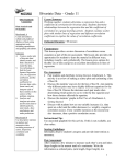
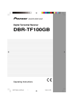
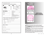
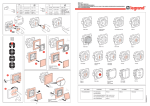
EtherHaul 1200™ 1ft Antenna Quick Setup Guide 1 3 Connecting the Cables P/N: IDOC001 Rev: A. Description: EH-QSINST-01 issue 1 Safety Notes This Quick Guide is intended as a handy reference for setting up the EtherHaul 1200™ ODU with integrated 1ft Antenna. This guide does not replace the full manual; please refer to the “EH-1200 Install and User Manual” for full installation and setup details. The Installation and maintenance of this link should be performed by service personnel who are properly trained and certified to carry out such activities. Make sure to disconnect all power cables before service! 1. Electrical Ground Point (GND) 6. Ethernet Cable RJ45 Interface (RJ2) ODU must be grounded using min 16AWG cable or according to local electrical code. 2. Power Connector Interface (PWR) 7. Fiber Cable SFP Interface (SFP2) For DC (21 ÷ 57 VDC) connection use a 2-wire cable (14-18 AWG) with 2 Amp circuit breaker on the live voltage (+ or -). The other poly should be grounded. 3. DVM Probe Interface (AUX) 8. System LEDs 4. Ethernet Cable RJ45 Interface (RJ1) 9. Reset Button (press for more than 5 seconds to restore factory defaults) 5. Fiber Cable SFP Interface (SFP1) 2 1. 2. Mounting 1ft Antenna Mount the ODU on a fixed reinforced steel mounting pole with 2-4 inches diameter. Assemble the Mounting Bracket and attach it to the pole according to following diagram: 1. Unit Mounting Screws and Bolts 2. Back Mounting Bracket 1. All cabling connected to the ODU should be outdoor-grade, with UV protection. 2. Shielded outdoor Cat5e cables terminated with metallic RJ45 connectors must be used. 3. Two Ethernet interfaces available, and can be configured to either electrical RJ45 (default) or optical SFP. 4. Connect the ground cable to the ODU GND point. 5. Power up the ODU using DC cable or 802.3at Power over Ethernet (PoE connection available via RJ1 port only). 6. In case of DC (21 ÷ 57 VDC), connect only the (+) and (-) wires to the DC terminal provided with the ODU. 3. Front Mounting Bracket 4. Quick Release Plate (Attached to ODU) 5. Quick Release Hooks 6. Azimuth Adjustment Lock Bolts 7. Elevation Adjustment Lock Bolts 4 Connectors Weatherproof Use the provided protective All-Weather Shells as described in the following diagram (fits cables from 3.5mm to 9.0mm diameter). 8. Azimuth Fine Adjustment Screw (± 8) 1. Cable Inlet Portion 9. Elevation Fine Adjustment Screw (± 16) 2. Rubber Gasket Insert 10. Elevation Screw Tension Band and Pin 3. Connector Outlet Portion 4. Cable 3. 4. 5. 6. Position the Azimuth and Elevation Adjustment Lock Bolts at 0 degrees (in the middle of the scale) and unlock them to allow free movement during alignment. Use care to avoid damaging or scratching the antenna radome: Do not touch the radome when unpacking the ODU. CAUTION: Do not rest the ODU face down to prevent scratches. Prevent all contact between the radome and other objects. By default, the ODU is delivered with the Quick Release Plate attached in a vertical polarization. If necessary, change the ODU polarization by rotating the Quick Release Plate so the arrow will point the “H” (horizontal) mark on the back of the ODU. Mount the ODU on the bracket using the Quick Release Hooks and slide it firmly inwards. Stretch the Elevation Screw Tension Band slightly and connect it to its mating Tension Pin, located on the Quick Release Plate. 1. 2. 3. 4. 5. 6. 7. Thread the cable connector through the Cable Inlet Portion () of the shell, through the Rubber Gasket () and through the Connector Outlet Portion (). Choose Rubber Gasket that best fits the cable diameter (note the Rubber Gasket is spliced and can be assembled on cables with connectors). Connect the cable connector to the ODU interface. Screw the Connector Outlet Portion () to the ODU firmly by hand (do not use tools). Insert the Rubber Gasket snugly into the Connector Outlet Portion () of the shell. Screw the Cable Inlet Portion () to the Connector Outlet Portion () firmly by hand (do not use tools). When removing All-Weather Shell, make sure to unscrew the Cable Inlet Portion () first, making sure the Connector Outlet Portion () does not move and only then remove the Connector Outlet Portion () from the ODU port. 5 LED PWR (Power) Color Green – Power OK Red – Power Failure Off – ODU off RF Green – Link Up Orange – Alignment Mode Off – Link Down Green – Link (Carrier) 1G Orange – Link (Carrier) 10/100 Off – No Link (Carrier) ETH1/2: 66 Note that changing the Date & Time will terminate your connection and you will have to reconnect and launch the Web EMS. System LEDs Description Blink Green – Device boot (~90 sec) 4. To view and configure IP address, click System and then IP, setting: Index (#) – 1, IP Address, Prefix Length – in mask bits, VLAN – 0. Click Apply when finished. Note that changing the IP address will terminate your connection and you will have to reconnect and launch the Web EMS using the new IP. Blink Green – 1G activity Blink Orange – 10/100 activity 5. To view and configure IP default gateway, click System and then Route, setting: Index (#) – 1, Destination – 0.0.0.0, Prefix Length – 0, Next Hop – gateway address. Click Apply when finished. Aligning the Antenna 1. Perform a coarse Azimuth and Horizontal alignment using a line-of-sight visual check with the remote ODU. Lock the Mounting Bracket to the pole using a 13mm/0.5” open wrench. 6. To view and configure the Ethernet ports parameters, click the interface icon on the main screen. To configure the port for optical SFP, set Ethernet Type to 1000xfd. Click Apply when finished. 2. Once ODU is powered up, switch both ODUs to Alignment Mode by inserting the Digital Volt Meter probes into the DVM Probes at the AUX Interface. Following this action, the RF LED color indicator will turn orange, indicating the ODU is in Alignment mode. The ODU will remain in Alignment Mode even if the DVM probes are ejected, until the ODU is rebooted. 7. To view and configure RF parameters, Click Radio. Click Apply when finished. 3. Read the receive level (RSSI) using the DVM. The voltage reading will be between 0 to 1Vdc, indicating the RSSI in dBms (for example 0.45V=-45dBm). value is Auto, meaning the role will be set automatically by the link. You can check the current set role in the Role Status field. Manually setting the Role is necessary only for asymmetric configurations. Transmit Asymmetry – Default value is symmetric configuration: 50% for Tx and Rx (50tx-50rx). For an asymmetric configuration (75%/25% or 90%/10%), you will have to manually configure the Role and set the Master unit to 75tx-25rx (or 90tx-10rx) and the Slave unit to 25tx-75rx (or 10tx-90rx). Mode – Default value is Adaptive (Adaptive Bandwidth, Code and Modulation), meaning the ODU will switch to the highest modulation profile available by data-rate license and link condition. In Adaptive mode, the modulation profile the ODU has reached is available in the Modulation, Sub-Channels, Repetitions and FEC fields. Operational Status – Displays the radio link status (Up or Down). RSSI (dBm) – the Receiver Signal Strength Indicator displays the received signal level. CINR (dB) – Displays the Carrier to Interference + Noise ratio, which indicates the radio link’s signal quality. In normal conditions, CINR≥17 indicates a good signal quality. Tx Power (dBm) –ODU’s transmit power (+5 to -35dBm). Default value is +5dBm. Reduce the Tx power in case of short links, making sure the RSSI at the remote ODU does not exceed -35dBm. 8. To view the loaded license configuration, click Advanced Settings and then Licensing. Check the currently enabled licenses (features-set and data-rate). 4. Perform fine Azimuth and Elevation alignment using the fine adjustment bolts, identifying the main lobe until the expected receive level is achieved (within +/-4dB). 5. Once the optimum position has been achieved, tighten the azimuth adjustment lock bolts on one ODU first. 6. Tightening the azimuth adjustment lock bolts will tilt the ODU, so realign the elevation again for optimum position and then tighten the elevation adjustment lock bolts. 7. Use the DVM to verify that the received signal level has not changed on ODU after final tightening of the brackets. 8. Repeat steps 5-7 on the second ODU. Antenna alignment is now complete. Initial System Setup 7 1.1Disconnect the DVM and reboot both ODUs by shortly pressing the ODU Reset Button. This returns the ODU to Adaptive Mode (ODU’s default operational mode). Following this action, and after the ODU has finished rebooting, the RF LED color indicator on both ODUs will turn Green, indicating that the radio link is Up. Frequency (MHz) – select from list (default values is 74375). Channel Width (MHz) – 250MHz or 500MHz. Default value is 500. Role –In a link, one side must be set to Master and the other side must be set to Slave (required for link synchronization). Default 9. To save the ODU’s configuration, click Save Configuration on the Web EMS Main screen. Note: 2. Carefully reinsert and tighten the AUX port protective seal. If you do not click Save Configuration, saving the currently running configuration to the startup configuration, all changes made will be lost upon the next ODU reset. The EtherHaul link can now pass traffic and management between the ports and over the radio link. For further radio link configuration, connect to the ODU using the Web EMS. 8 Basic Configuration Using Web EMS 9 Support Contacts Contact your local distributor for the technical support. 1. Launch an Internet browser and enter the ODU’s IP address in the address bar. For the default IP address enter: https://192.168.0.1. Technical support for Siklu’s direct customers: 2. Wait for the Java Applet to load and enter the username and password (default read/write access: admin, admin). Download your copy of the “EH-1200 Install and User Manual” from ftp://85.17.162.140/ (user: installmanual, password: siklu). 3. To view and configure system information, click System and then System Information, setting: ODU Name, Date (YYYY.MM.DD) and Time (HH:MM:SS). Click Apply when finished. • Siklu Support - [email protected]; • Siklu Support (US & Canada) - [email protected] Watch us install and setup a link at www.youtube.com (search: Siklu Etherhaul Installation) Siklu Communication Ltd. 43, Hasivim St, Petach-Tikva 49517, Israel