1
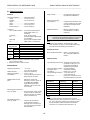
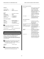
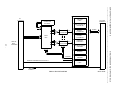
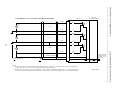
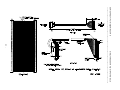
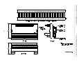
SERIES PMC341 PCI MEZZANINE CARD SIMULTANEOUS ANALOG INPUT MODULE ___________________________________________________________________________________________ The information contained in this manual is subject to change without notice. Acromag, Inc. makes no warranty of any kind with regard to this material, including, but not limited to, the implied warranties of merchantability and fitness for a particular purpose. Further, Acromag, Inc. assumes no responsibility for any errors that may appear in this manual and makes no commitment to update, or keep current, the information contained in this manual. No part of this manual may be copied or reproduced in any form, without the prior written consent of Acromag, Inc. Table of Contents 1.0 GENERAL INFORMATION........................................... KEY PMC341 FEATURES............................................ PCI MEZZANINE CARD INTERFACE FEATURES....... SIGNAL INTERFACE PRODUCTS............................... PMC MODULE ActiveX CONTROL SOFTWARE........ PMC MODULE VxWORKS SOFTWARE…….............. 2.0 PREPARATION FOR USE............................................ UNPACKING AND INSPECTION.................................. CARD CAGE CONSIDERATIONS................................ BOARD CONFIGURATION........................................... Software Configuration…….……............................ CONNECTORS………….............................................. Front Panel Field I/O Connector ……........................ Rear J4 Field I/O Connector………………………….. Analog Inputs: Noise and Grounding Considerations. External Trigger Input/Output.................................... PMC Local Bus Connector ……................................ 3.0 PROGRAMMING INFORMATION................................. PCI Configuration Address Space............................. Configuration Registers............................................. MEMORY MAP…………………..................................... Interrupt Register…………………….……………… Control Register………………………………..…..….. Channel Enable Control Register………...........…..... Low Bank Timer Register……………………….….. High Bank Timer Register…..…………………….….. Memory Threshold Register…………………….…..… Start Convert Register………………………….…..…. Memory Buffer………………………………….…..…. Analog Input & Corresponding Digital Codes……..… Reference Voltage Access Register......................…. Reference Voltage Read Data/Status Register........ MODES OF CONVERSION.......…...........…........ Single Conversion Mode………..…………..…..…. Continuous Conversion Mode….………….......…….. PROGRAMMING CONSIDERATIONS…...........….... Single Conversion Mode Example……………..…... Continuous Conversion Mode with Interrupt Example USE OF CALIBRATION REFERENCE SIGNAL.....…... Uncalibrated Performance…………….................…... Calibrated Performance……………………………..... Calibrated Programming Example…...........…...….. Programming Interrupts ……………...........……...….. 4.0 THEORY OF OPERATION............................................ FIELD ANALOG INPUTS.............................................. LOGIC/POWER INTERFACE....................................... PCI INTERFACE LOGIC............................................... BURST READ OF PMC341 MEMORY.......................... CONVERSION CONTROL LOGIC…………….…… MULTIPLEXER CONTROL CIRCUITRY………….….. DATA TRANSFER FROM ADC TO FPGA............…..... CONVERSION COUNTER………........….............…..... MEMORY BUFFER SWITCH CONTROL...................... EXTERNAL TRIGGER.………................................…... INTERRUPT CONTROL LOGIC…......................…...... REFERENCE VOLTAGE MEMORY CONTROL LOGIC. Page 2 3 3 3 3 4 4 4 4 4 4 4 4 5 5 5 5 6 7 7 7 7 8 9 9 9 10 10 10 10 11 11 11 11 12 12 12 12 13 13 13 13 14 14 14 15 15 16 16 16 16 16 16 16 16 16 -2- 5.0 SERVICE AND REPAIR................................................ SERVICE AND REPAIR ASSISTANCE........................ PRELIMINARY SERVICE PROCEDURE...................... 17 17 17 6.0 SPECIFICATIONS......................................................... PHYSICAL…………………...............................…......... ENVIRONMENTAL………………………………..….. ANALOG INPUT....….................................................... PCI Local Bus Interface..………………......................... 17 17 17 18 19 APPENDIX.................................................................... CABLE, SCSI-2 to Flat Ribbon (Shielded): MODEL 5028-187……….............................................. TERMINATION PANEL: MODEL 5025-552................... 19 19 DRAWINGS 4501-844 PMC MECHANICAL ASSEMBLY................. 4501-878 PMC341 BLOCK DIAGRAM......................... 4501-879 ANALOG INPUT CONNECTION.................. 4501-758 CABLE, SCSI-2 to Flat Ribbon (Shielded) 5028-187…………………….............................. 4501-464 TERMINATION PANEL 5025-552................ Page 20 21 22 23 19 24 IMPORTANT SAFETY CONSIDERATIONS It is very important for the user to consider the possible adverse effects of power, wiring, component, sensor, or software failures in designing any type of control or monitoring system. This is especially important where economic property loss or human life is involved. It is important that the user employ satisfactory overall system design. It is agreed between the Buyer and Acromag, that this is the Buyer's responsibility. Trademarks are the property of their respective owners. 1.0 GENERAL INFORMATION The PCI Mezzanine Card (PMC) Series PMC341 (14-bit) module is a precision, single size PMC module with simultaneous sampling of analog input signals. Sixteen differential analog input channels are provided with an input range of 10 volts. The 16 differential analog voltage input channels are converted as two banks of eight channels. After the first bank of eight channels are simultaneously converted, the second bank of 8 channels can then be simultaneously converted at the time specified in a user programmable delay counter. All 16-channels share two generous 512-sample memory buffers, from which digitized values are read. Since all channels share the same memory buffer, data tagging is implemented for easy identification of corresponding channel data. To minimize CPU interaction, interrupt generation is also supported upon reaching a programmable memory full threshold condition. The PMC341 utilizes state of the art Surface-Mounted Technology (SMT) to achieve its wide functionality and is an ideal choice for a wide range of industrial and scientific applications that require, high-performance analog inputs.