1
MAGPOWR TENSION CONTROL
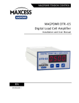
MAGPOWR DTR-65
Digital Load Cell Amplifier
Installation and User Manual
EN
MI 850A349 1 C
CONTENTS
INTRODUCTION
1-1
About these operating instructions ...................................................................... 1-1
Product overview .................................................................................................. 1-2
Model number key ............................................................................................... 1-2
SAFETY INSTRUCTIONS
2-1
Instructions for use .............................................................................................. 2-1
Safety symbols ..................................................................................................... 2-1
Basic safety information ....................................................................................... 2-3
INSTALLATION
3-1
Mechanical ........................................................................................................... 3-1
Electrical .............................................................................................................. 3-4
Complete DTR-65 wiring ................................................................................. 3-6
Load cell wiring detail ...................................................................................... 3-7
Convert wiring ................................................................................................. 3-8
From LCA to DTR-65 .................................................................................. 3-8
From DTR to DTR-65 .................................................................................. 3-9
OPERATION
4-1
Power on .............................................................................................................. 4-1
Zero the tension display ....................................................................................... 4-2
Reset parameters ................................................................................................. 4-2
Tension over-range.............................................................................................. 4-2
Password protection ............................................................................................. 4-2
Programming mode ............................................................................................. 4-3
Parameter number ........................................................................................... 4-3
Tension calibration............................................................................................... 4-5
Precision calibration ........................................................................................ 4-5
Weightless calibration ...................................................................................... 4-8
Tension calibration errors .................................................................................. 4-11
Entering maximum tension ................................................................................ 4-12
PARAMETERS
5-1
Filtering................................................................................................................ 5-1
Analog output scaling .......................................................................................... 5-1
Alarm setup and operation ................................................................................... 5-2
Digital input threshold ......................................................................................... 5-3
Calibrate the analog outputs ................................................................................ 5-3
Password .............................................................................................................. 5-4
Miscellaneous....................................................................................................... 5-5
MAINTENANCE
6-1
Fuse replacement ................................................................................................. 6-1
DTR-65 Assembly ........................................................................................... 6-2
TROUBLESHOOTING
www.maxcessintl.com
7-1
MAGPOWR DTR-65
MI 850A349 1 C
CONTENTS
SPECIFICATIONS
8-1
SERVICE
9-1
APPENDIX A: DLCA FLOWCHART
10-1
FIGURES
Figure 1. DTR-65 dimensions. .......................................................................................... 3-2
Figure 2. Installation of the DTR-65 into a panel. ............................................................. 3-3
Figure 3. Complete DTR-65 wiring. .................................................................................. 3-6
Figure 4. Load cell wiring detail. ....................................................................................... 3-7
Figure 5. LCA and DTR-65 pinout. .................................................................................... 3-8
Figure 6. DTR and DTR-65 pinout. .................................................................................... 3-9
Figure 7. Apply calibration tension.................................................................................... 4-7
Figure 8. Weightless calibration angles. ............................................................................ 4-9
Figure 9. Access to the DTR-65 fuses and fuse locations. ................................................. 6-1
Figure 10. Re-assembly of DTR-65 boards into the enclosure. ......................................... 6-3
TABLES
Table 1. Convert wiring from LCA to the DTR-65. ............................................................. 3-8
Table 2. Convert wiring from a DTR to the DTR-65. ......................................................... 3-9
Table 3. Load cell diagnostic errors. ................................................................................. 4-1
Table 4. Load cell calibration errors. ............................................................................... 4-11
www.maxcessintl.com
MAGPOWR DTR-65
MI 850A349 1 C
1–1
INTRODUCTION
About these
operating
instructions
All of the information herein is the exclusive proprietary
property of Maxcess International, and is disclosed with the
understanding that it will be retained in confidence and will
neither be duplicated nor copied in whole or in part nor be
used for any purpose other than for which disclosed.
Copyright 2013, all rights reserved.
Periodically there will be updates to this manual. The latest
version is available at www.maxcessintl.com or by calling your
regional office listed on the back page of this publication.
These digital load cell amplifiers must not be installed or used
in a machine or system which does not comply with the
machinery directive 2006/42/EC.
These digital load cell amplifiers were designed and
manufactured to be installed as Partly Completed Machinery
into a machine or partly completed machine.
The instructions must be read and used by all persons who
have the responsibility of installing and maintaining this digital
load cell amplifier.
These instructions must be retained and incorporated in the
technical documentation for the machine or partly completed
machinery into which the digital load cell amplifier is installed.
CE marking
This digital load cell amplifier is marked with the CE sign
according to the EMC directive 2004/108/EC and the low
voltage directive 2006/95/EC.
Conventions used in
this manual
All dimensions and specifications are shown in the format mm
[inches] unless specified otherwise.
Language
These are the original instructions, written in English.
www.maxcessintl.com
MAGPOWR DTR-65
MI 850A349 1 C
1–2
INTRODUCTION
Product overview
The DTR-65 is a digital tension readout and amplifier which
provides excitation voltage for load cells and amplifies the
returned millivolt signal which is proportional to applied
force into a 0 to 10 V, 4 to 20 mA, and a 0 to 1mA signal.
The DTR-65 shows the signal converted into a digital
readout in engineering units representing applied force.
The DTR-65 is panel mounted and provides IP65 protection
on the front face and IP20 protection on the back and sides.
The IP65 protection is provided by a gasket and a
membrane keypad.
All calibrations and setup are entered using a keypad and a
4-digit display. Tension is displayed using three significant
digits. The DTR-65 has a front panel tension zero button
and a digital input to remotely zero tension.
The DTR-65 has an alarm output which can be programmed
to activate at either a high or low tension threshold. Load
cell diagnostics run during power-up.
Model number key
The model number and serial number are shown on the
bottom of the enclosure.
The model number consists of the base model "DTR-65"
followed by optional alphanumeric characters.
Model format: DTR-65
Serial number format: MMDDYYNNNL
MM = month
DD = day
YY = last two digits of the year
NNN = a sequence number
L = manufacturing location
www.maxcessintl.com
MAGPOWR DTR-65
MI 850A349 1 C
2–1
SAFETY INSTRUCTIONS
Instructions for
use
To ensure safe and problem free installation of the digital load
cell amplifier, the digital load cell amplifier must be properly
transported and stored, professionally installed and placed in
operation. Proper operation and maintenance will ensure a long
service life of the device. Only persons who are acquainted with
the installation, commissioning, operation and maintenance of the
system and who possess the necessary qualifications for their
activities may work on the digital load cell amplifier. Note: The
safety information may not be comprehensive.
Please note the following:
The content of these operating instructions
Any safety instructions on the device
The machine manufacturer’s specifications
All national, state, and local requirements for installation,
accident prevention and environmental protection
Safety symbols
Information about
safety symbols
The safety instructions and symbols described in this section are
used in these operating instructions. They are used to avoid
possible dangers for users and to prevent material damage.
SIGNAL WORD
Source of danger and its results
Avoiding dangers
The signal word DANGER refers to the danger of death or serious
bodily injuries.
The signal word WARNING refers to the danger of moderate to
severe bodily injuries.
The signal word CAUTION refers to the danger of slight to
moderate bodily injuries or material damage.
The signal word NOTICE refers to the possibility of damage to
equipment.
www.maxcessintl.com
MAGPOWR DTR-65
MI 850A349 1 C
2–2
Symbols used
SAFETY INSTRUCTIONS
The following safety identification symbols are used in these
operating instructions.
WARNING/CAUTION – General danger or important note
Reference to general hazards that may result in bodily injuries or
damage to device or material.
WARNING/CAUTION – Danger due to crushing
Reference to danger of injury caused by crushing.
WARNING/CAUTION – Danger due to cutting
Reference to danger of injury caused by cutting.
WARNING/CAUTION – Danger due to voltage, electric shock
Reference to danger of injury caused by electric shock due to
voltage.
WARNING/CAUTION – Danger due to hot surfaces
Reference to risk of injury caused by burning.
www.maxcessintl.com
MAGPOWR DTR-65
MI 850A349 1 C
2–3
SAFETY INSTRUCTIONS
Basic safety
information
Proper use
The digital load cell amplifier is intended to be used on machines
or systems to amplify the signal from MAGPOWR or competitor load
cells.
Indoor operation, see environmental specifications.
Improper use
Operation outside the technical specifications
Operation in an Ex-area or intrinsically safe area
Outdoor operation
Any other use than the proper use shall be deemed inappropriate
Installation and commissioning
Any digital load cell amplifier which is damaged must not be
installed or put into operation.
Only perform installation, maintenance or repair tasks on the digital
load cell amplifier when the machine into which the DTR-65 is
installed has been stopped and is secured from being turned on.
Only perform installation, maintenance or repair tasks on the digital
load cell amplifier when there is no electrical power in the system.
The digital load cell amplifier must be securely mounted before
being placed in operation.
Only replacement parts obtained from Maxcess may be used.
No modifications may be made to the digital load cell amplifier.
Do not place electrical cables under mechanical strain.
continued
www.maxcessintl.com
MAGPOWR DTR-65
MI 850A349 1 C
2–4
SAFETY INSTRUCTIONS
Basic safety
information
continued
WARNING – Shock may result from water or conductive particles
entering the DTR-65 enclosure due to poor gasket sealing on the
front panel.
To maintain the IP65 rating on the front panel, be sure the gasket is
properly seated between the DTR-65 front panel and the panel into
which the DTR-65 is installed.
WARNING – Death or injury can result from unexpected movement
of the machine into which the DTR-65 is installed.
Protect against unexpected movement by removing electrical power
from the digital load cell amplifier and the machine into which the
digital load cell amplifier is being installed.
WARNING – Death or injury from shock may result from wiring live
power to the DTR-65.
Be sure the power is turned off and locked out before wiring the
DTR-65.
WARNING – Death or injury can result from electric shocks.
Safety requirements require a connection between the DTR-65
earth ground and the PE circuit of the building or machine.
continued
www.maxcessintl.com
MAGPOWR DTR-65
MI 850A349 1 C
2–5
SAFETY INSTRUCTIONS
Basic safety
information
continued
Operation
None, as tasks from the operator are generally not required.
Maintenance and repair
WARNING – Death or injury can result from unexpected
movement of the machine into which the DTR-65 is installed.
Protect against unexpected movement by removing electrical
power from the digital load cell amplifier and the machine into
which the digital load cell amplifier is installed.
WARNING – Danger of injury from crushing.
Maintenance and repair tasks on the digital load cell amplifier
must be performed only when the machine into which the
DTR-65 has been installed has been stopped and has been
secured from being turned on again.
WARNING – Death or injury from shock may result from wiring
live power to the DTR-65.
Be sure the power is turned off and locked out before wiring
the DTR-65.
Decommissioning
The digital load cell amplifier must be disposed of in
accordance with all the applicable national, state and local
regulations.
www.maxcessintl.com
MAGPOWR DTR-65
MI 850A349 1 C
3–1
INSTALLATION
Mechanical
installation
WARNING – Death or injury can result from unexpected
movement of the machine into which the DTR-65 is installed.
Protect against unexpected movement by removing electrical
power from the digital load cell amplifier and the machine into
which the digital load cell amplifier is installed.
WARNING – Danger of injury from crushing.
Maintenance and repair tasks on the digital load cell amplifier
must be performed only when the machine into which the
DTR-65 is installed has been stopped and has been secured
from being turned on again.
WARNING – Shock may result from water or conductive
particles entering the DTR-65 enclosure due to poor gasket
sealing on the front panel.
To maintain the IP65 rating on the front panel, be sure the
gasket is properly seated between the DTR-65 front panel and
the panel into which the DTR-65 is installed.
www.maxcessintl.com
MAGPOWR DTR-65
MI 850A349 1 C
3–2
INSTALLATION
Mechanical installation
continued
1. Remove the panel jacks from the back of the DTR-65.
2. Install the DTR-65 into a standard 1/8 DIN cut-out 92 x 45
[3.62 x 1.77] (Figure 1). Make sure the gasket is between
the DTR-65 front panel and the panel into which the DTR65 is being installed to maintain the IP-65 rating on the
DTR-65 front panel (Figure 2, page 3-3).
Figure 1. DTR-65 dimensions.
continued
www.maxcessintl.com
MAGPOWR DTR-65
MI 850A349 1 C
3–3
INSTALLATION
Mechanical installation
continued
3. Reinstall the panel jacks from the back of the DTR-65 into
the panel jack grooves in the side of the enclosure.
4. Install the set screws into the panel jack grooves and
tighten with the supplied allen wrench to secure the
DTR-65 in the panel and to form a seal on the gasket.
Tighten the set screws to a torque of 0.099 to 0.113 Nm
[14 to 16 oz. in.].
Figure 2. Installation of the DTR-65 into a panel.
www.maxcessintl.com
MAGPOWR DTR-65
MI 850A349 1 C
3–4
INSTALLATION
Electrical
installation
WARNING – Death or injury from shock may result from wiring
live power to the DTR-65.
Be sure the power is turned off and locked out before wiring
the DTR-65.
All wiring must comply with the essential requirements of the
appropriate standard(s) and is the responsibility of the
installer.
For fixed/permanent installation of the DTR-65, a suitable
switch or circuit-breaker must be installed as a disconnecting
device and this switch/circuit-breaker needs to be labelled
appropriately.
Wiring to the digital load cell amplifier must be insulated
copper wire with a temperature rating of at least 80⁰C. The
wire size must be at least 0.34 mm2 (22 AWG). Use twisted
pair cable for the power. Use shielded cable for the load cell
and analog output wiring.
The DTR-65 can be powered by either 100-240 VAC 50-60
Hz or by 24 VDC. Only connect to one power source.
www.maxcessintl.com
MAGPOWR DTR-65
MI 850A349 1 C
3–5
INSTALLATION
Electrical installation
continued
See Figure 3 for reference.
1. Connect power to the DTR-65. Only one power source is
needed.
For 100-240 VAC power
Connect 100-240 VAC to TB1 pins 1and 2 labeled AC L1
and AC L2.
For 24 VDC power
Connect a 24 VDC power supply to TB1 pins 4 and 5. Pin 4
should be positive.
2. Connect the PE of the building or machine to
TB1 pin 3 marked with the earth ground symbol.
Note: The negative power connection, TB1 pin 5, is
internally connected TB1 pin 3. This connection is used for
EMC compliance. TB1 pin 3 is also connected to all the
terminals labeled with SHLD which are TB1 pin 10, TB2 pins
5 and 6. TB1 pin 5 is also connected to all the terminals
labeled GND, TB1 pin 11, and TB2 pins 3 and 8.
WARNING – Death or injury can result from electric shocks.
Safety requirements require a connection between the DTR-65
earth ground and the PE circuit of the building or machine.
CAUTION – Never place electrical cables under mechanical
strain. Always provide mechanical support of wiring with either
clamps or flexible or rigid conduit.
3. Connect one or two load cells to TB1 pins 6, 7, 8, and 9.
See Figure 3. If using non-MAGPOWR half-bridge load
cells, see Figure 4 for wiring.
4. Calibrate the load cells by following the procedure starting
on page 4-5 (Precision) or 4-8 (Weightless).
Figure 3 on the next page shows the complete DTR-65 wiring.
Note: When using the AC supply input TB1 pin 4 does not
output +24 VDC. This pin is a power input only.
www.maxcessintl.com
MAGPOWR DTR-65
MI 850A349 1 C
3–6
INSTALLATION
Wiring for the DTR-65
Figure 3. Complete DTR-65 wiring.
www.maxcessintl.com
MAGPOWR DTR-65
MI 850A349 1 C
3–7
INSTALLATION
Wiring for the DTR-65
Figure 4. Load cell wiring detail.
www.maxcessintl.com
MAGPOWR DTR-65
MI 850A349 1 C
3–8
INSTALLATION
Convert wiring from
LCA to DTR-65
Table 1 shows how to convert the wiring from an LCA to the
DTR-65.
LCA
DTR-65
Terminal
Terminal
+24 V
12
TB1-4
Gnd
11
TB1-5
10
TB1-3
0 to 1 mA
9
TB2-4
4 to 20 mA
8
TB2-7
Gnd
7
TB2-8
0 to 10V
6
TB2-9
Shield
5
TB2-5, TB2-6, TB1-10
P+
4
TB1-9
P-
3
TB1-8
S-
2
TB1-7
S+
1
TB1-6
Function
Earth Ground
Table 1. Convert wiring from LCA to the DTR-65.
Figure 5. LCA and DTR-65 pinout.
www.maxcessintl.com
MAGPOWR DTR-65
MI 850A349 1 C
3–9
INSTALLATION
Convert wiring from
DTR to DTR-65
Table 2 shows how to convert the wiring from a DTR to the
DTR-65.
DTR
DTR-65
Terminal
Terminal
AC L1
L1
TB1-1
AC L2
L2
TB1-2
None
TB1-3
Gnd
GND
TB2-8
0 to10V
+OUT
TB2-9
Shield
None
TB2-5, TB2-6, TB1-10
P+
+P RED
TB1-9
P-
-P GRN
TB1-8
S-
-S BLK
TB1-7
S+
+S WHT
TB1-6
Function
Earth Ground
Table 2. Convert wiring from a DTR to the DTR-65.
Figure 6. DTR and DTR-65 pinout.
www.maxcessintl.com
MAGPOWR DTR-65
MI 850A349 1 C
4–1
OPERATION
Operation
DTR-65 control
buttons
There are three manual control buttons on the DTR-65.
[+]
= increment
[-]
= decrement
[]
= zero tension, or
enter or save function
Power on
The DTR-65 will display the software version number when
power is first applied for five seconds and then the DTR-65 will
start displaying the tension. During the software version display,
diagnostics are performed on the load cells and any errors are
displayed.
The load cell diagnostic errors are shown in Table 3.
To exit from the load cell diagnostic error, press [] and the
tension will be displayed.
If no errors are detected, the tension will be displayed.
Display
Meaning
Er 10
Sensor White (S+) or Black (S-) wire disconnected.
Er 11
Sensor Red (P+) wire disconnected.
Er 12
Sensor Green (P-) wire disconnected.
Er 13
Sensor Failure or other miswiring error. Example: Green and White wire are
swapped, etc.
Table 3. Load cell diagnostic errors.
www.maxcessintl.com
MAGPOWR DTR-65
MI 850A349 1 C
4–2
OPERATION
Zeroing tension
display
While displaying tension, press [] for two seconds to zero the
displayed tension and output.
Connecting the digital input (Zero) to either +5V or +24V for
greater than 500 ms will zero the displayed tension and
output.
This function will work only when the following conditions are
met:
when displaying tension and not if in the parameter menu,
when not in calibration,
if zeroing has not been locked out when a password has
locked the DLCA.
Reset parameters to
defaults
Press and hold [+] and [] while turning power on to the
DTR-65. The display will show "dEF" for four seconds while the
parameters are reset to defaults.
This does not reset the calibrate analog output parameters
C0.1 through C0.6. These parameters are calibrated at the
factory for the component tolerances on each board. The
password is reset and the DTR-65 will be unlocked.
Tension over-range
The tension reading display will flash when the displayed
tension exceeds the maximum tension set in either parameter
C1.3 or C2.5.
Password protection
The DTR-65 allows a password to be set which prevents
changes to the parameters or performing a calibration. When
locked, all parameters can be viewed. Only zeroing tension is
allowed while the password has locked the DTR-65, unless
zeroing has been locked out.
www.maxcessintl.com
MAGPOWR DTR-65
MI 850A349 1 C
4–3
OPERATION
Programming
mode
Enter the programming menu
Press and hold [+] and [-] for two seconds.
Exit the programming menu
Press and hold [+] and [-] for two seconds.
Also: While showing parameter P.24, you may press [] to exit
the menu and return to displaying the tension.
Parameter number
While in the programming mode, the display shows P.xx, where
xx is the parameter number.
Press [+] or [-] to increment or decrement the parameter
number. Press [] to enter the data entry mode for a
parameter. Use [+] or [-] to change the value of a parameter.
Press [] and release to cancel the data change and return to
the menu. Press [] and hold for two seconds (until the display
starts flashing) to save the changed parameter. If the data has
been changed and the data has not been saved, after five
seconds of no button activity the display will flash indicating
the data needs to be saved.
The CAL1 and CAL2 menus are sub-menus which are used to
step the operator through the calibration sequence. Press []
when a CALx menu is showing to get into the sub-menu. The
parameters will now be labeled Cx.y.
continued
www.maxcessintl.com
MAGPOWR DTR-65
MI 850A349 1 C
4–4
OPERATION
Programming
mode
Parameter number
continued
When in the programming mode and no buttons have been
pressed for two minutes, the DTR-65 exits the programming
mode and returns to displaying tension. This menu time-out is
not active once any of the calibration loops have been entered.
The DTR-65 allows a password to be set which prevents
changes to the parameters or performing a calibration. When
locked, all parameters can be viewed. Only zeroing tension is
allowed while the password has locked the DTR-65, unless
zeroing has been locked out.
www.maxcessintl.com
MAGPOWR DTR-65
MI 850A349 1 C
4–5
OPERATION
Tension calibration
The DTR-65 allows either precision calibration or weightless
calibration. The Precision Calibration method is described
below. Weightless Calibration begins on page 4-8.
Calibration can only be performed when the password has not
locked the DTR-65. To unlock the DTR-65, see the Password
parameter P.00 on page 5-4.
Precision calibration
Use this method when applying a known weight with a rope in
the web path to the load cells for calibration. Typically this
should be 10% of the load cell rating or greater.
Enter the programming mode by pressing and holding [+] and
[-] for two seconds.
Use the [+] and/or [-] buttons to go to parameter P.01. Press
[] to see the present load cell excitation voltage. Select either
5V or 7.5V. When using MAGPOWR load cells select 7.5V. Press
and hold [] for two seconds (until the display starts flashing)
to store the changes.
Use the [+] and/or [-] buttons to go to "CAL1". Press [] to
enter the CAL1 sub-menu.
Display now shows C1.1. Unload the load cell roller and press
[]. The DTR-65 will now zero out the idler roll weight and
show a wait display. After zeroing, the DTR-65 will
automatically increment to the next parameter.
continued
www.maxcessintl.com
MAGPOWR DTR-65
MI 850A349 1 C
4–6
OPERATION
Tension calibration
Precision calibration
continued
Display now shows C1.2. Press [] and select the decimal point
position for tension. Press and hold [] for two seconds (until
the display starts flashing) to store the decimal point position
chosen. Range {0000, 0000., 000.0, 00.00, 0.000}.
Display now shows C1.3. Press [] and enter the maximum
tension. Press and hold [] for two seconds (until the display
starts flashing) to store the parameter. This value scales the
output. The output will be at 10 volts or 20 mA when the
measured tension matches this value. The maximum output
voltage or current is set by parameters P.07, P.09, and P.11.
Range {0, 9990}.
Display now shows C1.4. Press [] and enter the calibration
tension that will be applied to the load cell. Press and hold []
for two seconds (until the display starts flashing) to store the
parameter. Range {0, 9990}.
continued
www.maxcessintl.com
MAGPOWR DTR-65
MI 850A349 1 C
4–7
OPERATION
Tension calibration
Precision calibration
continued
Display now shows C1.5. Apply the calibration load to the load
cell using a temporary web or rope and a known weight
entered in C1.4. The temporaray web should follow the normal
web path. When using a rope, the rope should be centered on
the rollers. See Figure 7. Press [] to start calibration. The
display will show a wait screen, and then display PASS for a
successful calibration or an error code to indicate an issue with
the calibration.
1
Temporary web
2
Sensing roll
3
Weight (W)
Figure 7. Apply calibration tension.
From either the passing or error screen, press [] to return to
displaying tension.
See the calibration errors in Table 4 on page 4-11.
www.maxcessintl.com
MAGPOWR DTR-65
MI 850A349 1 C
4–8
OPERATION
Tension calibration
Weightless calibration
Use this method when applying a known weight is not
convenient or desired.
For Precision Calibration method, see page 4-5.
Enter the programming mode by pressing and holding [+] and
[-] for two seconds.
Use the [+] and/or [-] buttons to go to parameter P.01. Press
[] to see the present load cell excitation voltage. Select either
5V or 7.5V. When using MAGPOWR load cells select 7.5V. Press
and hold [] for two seconds (until the display starts flashing)
to store the changes.
Use the [+] and/or [-] buttons to go to CAL2. Press [] to enter
the CAL2 sub-menu.
Display now shows C2.1. Unload the load cell roller and press
[]. The DTR-65 will now zero out the idler roll weight and
show a wait display. After zeroing the DTR-65 will automatically
increment to the next parameter.
Display now shows C2.2. Press [] and select the decimal point
position for tension. Press and hold [] for two seconds (until
the display starts flashing) to store the decimal point position
chosen. Range {0000, 0000., 000.0, 00.00, 0.000}.
Display now shows C2.3. Press [] and enter the load cell
sensitivity in mV/V units. MAGPOWR load cells have a sensitivity
of 2.1 mV/V. (Consult the manual of competitor's load cells if
using non-MAGPOWR load cells.) Press and hold [] for two
seconds (until the display starts flashing) to store the
parameter. Range {000.1, 100.0}.
continued
www.maxcessintl.com
MAGPOWR DTR-65
MI 850A349 1 C
4–9
OPERATION
Tension calibration
Weightless calibration
continued
Display now shows C2.4. Press [] and enter the combined
load cell rating. Press and hold [] for two seconds (until the
display starts flashing) to store the parameter. Range {0,
9990}.
Display will now show C2.5. Press [] and enter the maximum
tension. Press and hold [] for two seconds (until the display
starts flashing) to store the parameter. This value scales the
output. The output will be at 10 volts or 20 mA when the
measured tension matches this value. The maximum output
voltage or current is set by parameters P.07, P.09, and P.11.
Range {0, 9990}.
Figure 8. Weightless calibration angles.
X = Web wrap angle
Y = Angle from force direction Arrow
Continued
www.maxcessintl.com
MAGPOWR DTR-65
MI 850A349 1 C
4–10
OPERATION
Tension calibration
Weightless calibration
continued
Display now shows C2.6. Press [] and enter the web wrap
angle in degrees. This is the angle over which the web touches
the idler roller. Press and hold [] for two seconds (until the
display starts flashing) to store the parameter. Refer to Figure
8 for the wrap angle 'X'. Range {0, 180.0}.
Display now shows C2.7. Press [] and enter the angle from
the force direction arrow or center line in degrees. This is the
angle between the resultant force from the web tension and the
force direction arrow of the load cell or centerline of the load
cell. The maximum value is 45 degrees. Press and hold [] for
two seconds (until the display starts flashing) to store the
parameter. Refer to Figure 8 for the angle from force direction
'Y'. Range {00.0, 45.0}.
Display now shows C2.8. Press [] to start the weightless
calibration. The display will show a wait screen, and then
display PASS for a successful calibration or an error code to
indicate an issue with the calibration.
From either the passing or error screen press [] to return to
displaying tension.
See the calibration errors in Table 4 on page 4-11.
If the displayed tension reads negative when force is applied to
the load cell, change parameter P.20 (Tension Polarity), to -1.
The displayed tension will now read positive when force is
applied.
www.maxcessintl.com
MAGPOWR DTR-65
MI 850A349 1 C
4–11
OPERATION
Tension calibration
errors
Display
PASS
Error description
Calibration was successful. No Errors found.
Signal read by the amplifier is too large when maximum tension is applied.
Er 1
This is caused by maximum tension being too large. Reduce maximum
tension.
Signal read by the amplifier is too small. Too little of the load cell range is
Er 2
being used, thus the gain is greater than 32:1. Use more of the load cell
range or set maximum tension higher.
Er 3
Er 4
Er 5
Roller weight too large. Roller weight exceeds 90% of the load cell rating.
Make roller weight smaller.
Calibration tension is greater than Maximum tension. Make Maximum
tension larger than Calibration tension.
Maximum tension exceeds the load cell rating. Lower wrap angle, make roll
weight smaller or get higher rated load cells.
Table 4. Load cell calibration errors.
www.maxcessintl.com
MAGPOWR DTR-65
MI 850A349 1 C
4–12
OPERATION
Entering maximum
tension
Examples
The following are examples of displaying tension that results
from the value entered for maximum tension and the selection
of the decimal point position. The DTR-65 displays tension with
three significant digits.
Example 1
Using two GTSD-15000M load cells:
The rated load is 30000 kg.
The application’s maximum tension is 15000 kg.
Enter decimal point position as 000.0.
Enter Maximum tension as 15.0.
The DTR-65 now displays tension with units of 1000 kg.
The display will increment in 100 kg steps.
Same application but desired units are Newtons:
The load cell’s rated load is 294 kN.
The application’s maximum tension is 147 kN.
Enter decimal point position as 0000.
Enter Maximum tension as 147.
The DTR-65 now displays tension with units of 1 kN.
The display will increment in 1 kN steps.
Same application but desired units are Pounds:
The load cell’s rated load is 66.1 kPounds.
The application’s maximum tension is 33.0 kPounds.
Enter decimal point position as 000.0.
Enter maximum tension as 33.0.
The DTR-65 will now display tension with units of
1 kPound.
www.maxcessintl.com
The display will increment in 0.1 kPound steps.
MAGPOWR DTR-65
MI 850A349 1 C
4–13
OPERATION
Entering maximum
tension
continued
Example 2
Using two GTSB-2200 load cells:
The rated load is 4400 lbs.
The application’s maximum tension is 2000 lbs.
Enter decimal point position as 00.00.
Enter Maximum tension as 2.00.
The DTR-65 now displays tension with units of 1000 lbs.
The display will increment in 10 lb steps.
Alternatively:
Enter decimal point position as 0000.
Enter maximum tension as 2000.
The DTR-65 will now display tension with units of 1 lbs.
The display will increment in 10 lb steps.
Note that the right-most zero is fixed and does not
change.
www.maxcessintl.com
MAGPOWR DTR-65
MI 850A349 1 C
5–1
PARAMETERS
Parameters
Filtering
The tension display and all 3 analog outputs have a separate low pass filter. The filter response
can be set from 100 Hz to 0.01 Hz.
Parameter #
Description
Units
Default
Range
P.02
Tension display filter frequency
Hertz
3
{00.01, 99.99}
P.03
0 to 10V output filter frequency
Hertz
40
{00.01, 99.99}
P.04
4 to 20mA output filter frequency
Hertz
40
{00.01, 99.99}
P.05
0 to1mA output filter frequency
Hertz
40
{00.01, 99.99}
Analog output scaling
Each analog output’s output values for zero tension and maximum tension can be set by the
following parameters.
Parameter #
P.06
Description
Units
Default
Range
Sets the 0 to 10V output voltage
volts
0
{00.00, 10.00}
volts
10
{00.00, 10.00}
milliamps
4
{00.00, 20.00}
milliamps
20
{00.00, 20.00}
volts
0
{00.00, 10.00}
volts
10
{00.00, 10.00}
when the tension is 0.
P.07
Sets the 0 to 10V output voltage
when the tension is equal to
maximum tension
P.08
Sets the 4 to 20mA output current
when the tension is 0.
Allows changing to a 0 to 20 mA
output
P.09
Sets the 4 to 20mA output current
when the tension is equal to
maximum tension
P.10*
Sets the 0 to 1mA output current
when the tension is 0
P.11*
Sets the 0 to 1mA output current
when the tension is equal to
maximum tension
* The voltage value entered in P.10 and P.11 represents the current value in milliamps when
divided by 10.
www.maxcessintl.com
MAGPOWR DTR-65
MI 850A349 1 C
5–2
PARAMETERS
Alarm setup and operation
The following parameters describe the setup and operation of the alarm output.
Parameter #
P.13
Description
Sets the alarm activation type.
0=
Default
Range
0
{0, 3}
Alarm ON when tension is above the alarm
high compare value
1=
Alarm ON when tension is below the alarm
low compare value.
2=
Alarm ON when tension is either above the
alarm high compare value or below the
alarm low compare value.
3=
Alarm ON when tension is below the alarm
high compare value and above the alarm low
compare value.
P.14
Alarm high compare value
500
{0, 9990}
P.15
Alarm low compare value
0
{0, 9990}
P.16
Alarm hysteresis percent
0
[Hysteresis percent is a percentage of maximum
[000.0, 100.0}
tension (value in C1.3 or C2.5).]
P.17
Alarm ON delay time [The alarm ON output is
0
{00.00, 99.99}
delayed by this number of seconds.]
P.18
Alarm OFF delay time [The alarm OFF output is
0
[00.00, 99.99}
delayed by this number of seconds.]
Alarm operation with hysteresis
Alarm activation type 0:
Alarm turns on when tension is greater than High value.
Alarm turns off when tension is less than (HighValue – (HysteresisPercent * MaximumTension))
Alarm activation type 1:
Alarm turns on when tension is less than Low value.
Alarm turns off when tension is greater than (LowValue + (HysteresisPercent * MaximumTension))
Alarm activation type 2:
Alarm turns on when tension is greater than High value or less than Low value.
Alarm turns off when tension is less than (HighValue - (HysteresisPercent * MaximumTension))
and when tension is greater than (LowValue + (HysteresisPercent * MaximumTension))
Alarm activation type 3:
Alarm output is the complement of alarm activation type 2.
www.maxcessintl.com
MAGPOWR DTR-65
MI 850A349 1 C
5–3
PARAMETERS
Digital input threshold
Parameter #
P.12
Description
Default
Range
Sets the digital input threshold for either 5V or 24V
24 volts
n/a
operation.
When set for 5V, the threshold between on and off
is 2.5 volts with 20% hysteresis.
When set for 24V, the threshold between on and
off is 12 volts with 20% hysteresis.
Calibrate the analog outputs (not normally changed)
CAL0 – These parameters set the offset and gain for the outputs to calibrate the outputs to real
volts or real current. The parameters compensate for component tolerances on each DTR-65.
These parameters are calibrated at the factory and are not reset by the power-up function reset
parameters to default.
If these need to be changed connect a volt meter or current meter as appropriate to the output
that is being calibrated.
Parameter #
C0.1
Description
Range
Sets the 0 to 10V output to 0%.
{0, 9999}
Change the value until the meter reads 0.00 volts
C0.2
Sets the 0 to 10V output to 100%.
{0, 9999}
Change the value until the meter reads 10.00 volts
C0.3
Sets the 4 to 20mA output to 0%.
{-999, 9999}
Change the value until the meter reads 0.00 milliamps.
C0.4
Sets the 4 to 20mA output to 100%
{0, 9999}
Change the value until the meter reads 20.00 milliamps
C0.5
Sets the 0 to 1mA output to 0%.
{0, 9999}
Change the value until the meter reads 0.00 volts or 0.00
milliamps
C0.6
Sets the 0 to 1mA output to 100%.
{0, 9999}
Change the value until the meter reads 10.00 volts or 1.00
milliamps.
www.maxcessintl.com
MAGPOWR DTR-65
MI 850A349 1 C
5–4
PARAMETERS
Password
Parameter #
P.00
Description
Range
Password
{0, 9999}
When the DTR-65 is locked, all parameters will be viewable but
cannot be changed and no calibrations can be performed.
To lock or unlock the DTR-65 press [] to show the lock or unlock
status, displayed as ULOC for unlocked and LOC for locked.
To lock the DTR-65 the password must be entered twice. To
unlock the DTR-65 the password only needs to be entered once.
To lock the DLCA
Press [] again and the display will show PAS1, press [] and enter
the password using the [+] and [-] buttons. Press and hold [] for
two seconds to enter the password.
The display now shows PAS2. Press [] and enter the same
password using the [+] and [-] buttons. Press and hold [] for two
seconds to enter the password.
The display now shows LOC for locked. Press [] to return to
displaying tension.
To unlock the DLCA
Press [] again and the display shows PAS1. Press [] and enter
the password using the [+] and [-] buttons. Press and hold [] for
two seconds to enter the password.
The display now shows ULOC if the correct password was entered.
Press [] to return to displaying tension.
If the password was incorrect, the display shows LOC and the
DTR-65 is still locked. Press [] to return to displaying tension,
and then repeat the unlock procedure.
www.maxcessintl.com
MAGPOWR DTR-65
MI 850A349 1 C
5–5
PARAMETERS
Miscellaneous
Parameter #
P.19
Description
Default
Tension number format
0
Tells whether tension display is 3-digit with no fixed right-hand
zero or 3-digit with fixed right-hand zero.
0=
Auto Select between formats. (Based on value in
Maximum Tension C1.3 or C2.5).
P.20
1=
3-digit with no fixed right-hand zero.
2=
3-digit with fixed right-hand zero.
Tension polarity
+1
Set to -1 to show positive tension when the force is acting in
the direction opposite the force direction arrow on the load
cells. Set automatically by Precision calibration.
P.21
DP position
0
Set the decimal point position to show when displaying tension
P.22
0=
0000
1=
0000.
2=
000.0
3=
00.00
4=
0.000
Lock out zeroing tension from [] button and digital input when
0
a password has locked the DLCA.
0=
Zeroing tension allowed when password has locked the
DLCA
1=
Zeroing tension locked out when password has locked
the DLCA
P.23
Firmware Version. Displays the firmware version.
P.24
Exit from menu and return to displaying tension
www.maxcessintl.com
MAGPOWR DTR-65
MI 850A349 1 C
6–1
MAINTENANCE
Maintenance
No regular maintenance is required on the DTR-65.
Fuse replacement
There are four fuses in the DTR-65. To access:
1. Remove the DTR-65 from the panel.
2. Remove the four corner pan head screws on the DTR-65
back panel.
3. Carefully slide out the board assembly until all four fuses
are visible. Do not remove the board assembly farther than
this point.
F2
F3
F1
F4
Figure 9. Access to the DTR-65 fuses and fuse locations.
F1
F2, F3
F4
24 VDC input power
100-240 VAC input power
24 VDC into the main board
All fuses are 2.5A fast blow, 250 V. Recommended fuse part
numbers are listed on page 8-1 (Specifications).
continued
www.maxcessintl.com
MAGPOWR DTR-65
MI 850A349 1 C
6–2
MAINTENANCE
Fuse replacement
continued
4. After replacement of any bad fuses, carefully slide the
board assembly back into the enclosure.
5. Install the four pan head screws into the corners of the
back panel and tighten.
6. Re-install the DTR-65 into the panel using the panel
mount jacks, gasket, and set screws.
DTR-65 Re-assembly (if pulled out too far)
If the board assembly is pulled all the way out of the
enclosure, follow these steps to reinstall it without damaging
any components.
1. Install the board assembly into the enclosure on the
second groove from the bottom.
2. Slide the board assembly in until the keypad cable is just
flush with the back of the enclosure.
3. Use a small screwdriver to pull the cable so it makes a
loop over the top of the header P105 on the main board.
4. Carefully slide the board assembly the rest of the way into
the enclosure.
continued
www.maxcessintl.com
MAGPOWR DTR-65
MI 850A349 1 C
6–3
MAINTENANCE
DTR-65 Assembly
continued
Notice – Failure to loop the keypad cable over header P105 will
result in the keypad cable being compressed between the main
board and the front panel. This may put excessive strain on the
keypad cable ZIF connector and result is loss of keypad
response.
Loop in
keypad
cable
Figure 10. Re-assembly of DTR-65 boards into the enclosure.
www.maxcessintl.com
MAGPOWR DTR-65
MI 850A349 1 C
7–1
TROUBLESHOOTING
Fault description
Probable cause
Solution
Reference
Er 10 at power-up
Sensor White (S+) or
Check sensor wiring.
Figure 3. DTR-65 wiring
Check sensor wiring.
Figure 3. DTR-65 wiring
Check sensor wiring.
Figure 3. DTR-65 wiring
Check sensor wiring.
Figure 3. DTR-65 wiring
No power
Check power wiring
Figure 3. DTR-65 wiring
Fuse(s) blown
Check fuse(s) in DTR-65.
Fuse ratings in
Black (S-) wire
disconnected
Er 11 at powr-up
Sensor Red (P+) wire
disconnected
Er 12 at power-up
Sensor Green (P-) wire
disconnected
Er 13 at power-up
Sensor Failure or other
mis-wiring error
Example: Green and
White wire swapped, etc.
Display not lighted
Specifications; p. 8-1
Fuse Replacement; p. 6-1
Analog outputs not
Analog output shorted
changing with the
displayed tension
Check Analog output
Figure 3. DTR-65 wiring
wiring.
Analog output range
Check parameters P.06
misconfigured
through P0.11.
Analog output not
Perform output
calibrated
calibration CAL0.
Alarm output not
Alarm not wired
Check alarm wiring.
working
correctly
––
––
Figure 3. DTR-65 wiring
Alarm not configured
Check parameters P.13
––
correctly
through P.18
Remote zero not
Remote zero input not
Check remote zero
zeroing tension
wired correctly
wiring.
Digital input threshold
Check parameter P.12
––
Check parameter P.20.
––
Figure 3. DTR-65 wiring
level not set correctly
Displayed tension is
Tension polarity is
reading negative
wrong
value with increasing
tension.
Cannot change
Password protection is
Enter the password into
parameters or
active
P.00 to unlock the DTR-65.
perform calibration.
––
The master unlock
password is 6195.
www.maxcessintl.com
MAGPOWR DTR-65
MI 850A349 1 C
8–1
SPECIFICATIONS
General
Power
–
100-240 VAC +/-10%, 50-60 Hz, 0.09 A
or
24 VDC +/-10%, 0.14 A maximum
Note that the 24 VDC negative supply and earth ground are
interconnected.
The 24VDC power supply must have an SELV output, such
as Puls ML15.241, Mean Well MDR-20-24 or equivalent.
The Mean Well MDR-20-24 can be purchased from Fife as
part number 93157-024.
Internal fuses
–
2.5 A, fast-blow
Bussman GBD2.50, or Littelfuse 21702.5
Temperature range
Operating
-
DC supply: 0° to 50°C (32° to 122°F)
AC supply: 0° to 45°C (32° to 113°F)
Storage
-
-20° to 80°C (-4° to 176°F)
Enclosure
-
IP65 on front panel
IP20 on back and sides
Panel Thickness Range
–
2.54 [0.100] minimum, 9.53 [0.375] maximum
Panel Cut-Out
–
92 x 45 [3.62 x 1.77]
Climatic class
-
3K3 (EN60721)
Relative humidity
-
5% to 85%
Pollution degree
-
2 (IEC664-1)
Dimensions
–
Height - 51.6 mm (2.03 in)
Width – 98.4 mm (2.76 in)
Length – 172 mm (6.77 in)
Display
-
4-digit LED, 3-digit tension resolution
Display decimal point
-
selectable position
Maximum gain
-
32:1
Tare Adjustment
-
90% of Load Cell Rating
www.maxcessintl.com
MAGPOWR DTR-65
MI 850A349 1 C
8–2
SPECIFICATIONS
Inputs and outputs
Load cell excitation
-
5 VDC or 7.5 VDC, 100 mA Maximum
Load cell sensitivity
-
1.5 to 100 mV/V
0-10V analog output
-
0 to 10 VDC, 2k minimum load
4-20mA analog output
-
4 to 20 mADC, 450 ohm maximum load
0-1mA or 0-10V analog output
-
0 to 1 mADC, 1k maximum load
Alarm output
-
0 to10 VDC, open circuit
30 VDC maximum, 0.4 ADC maximum,
40 VDC isolation
Digital input (zero tension)
-
24 VDC maximum, 5V or 24V selectable threshold
Tension display
-
Max null drift: 0.02% of load cell rating per °C
0 to 10V output
-
Max null drift: 0.02% of load cell rating per °C
4 to 20mA output
-
Max null drift: 0.02% of load cell rating per °C
0 to 1mA / 0 to 10V output
-
Max null drift: 0.07% of load cell rating per °C
–
CE
Temperature drift
Certifications and
environmental
compatibility
Product certifications
TUV Rheinland of North America
to UL61010-1
and
CAN/CSA-C22.2 No. 61010-1 and
CB Certificate to IEC61010-1
RoHS
www.maxcessintl.com
MAGPOWR DTR-65
MI 850A349 1 C
9–1
SERVICE
Service requests
and replacement
parts
To request service or to get replacement parts, contact one of the
following addresses or your regional office listed at the bottom of
this page.
Fife
Fife-Tidland GmbH
222 West Memorial Rd.
Max-Planck-Strasse 8
Oklahoma City, OK, 73114
65779 Kelkheim
USA
Deutschland
Phone: 1.405.755.1600
Telefon: +49.6195.7002.0
Fax: 1.405.755.8425
Fax: +49.6195.7002.933
Web: www.maxcessintl.com
Web: www.maxcess.eu
When ordering replacement parts, please indicate, where possible,
part number, drawing number and model description.
If it is necessary to return the DTR-65 for service, care must be
taken to properly package the unit to prevent damage during
shipment. If possible, use the original shipping containers.
NORTH, CENTRAL
AND SOUTH AMERICA
EUROPE, MIDDLE EAST
AND AFRICA
CHINA
Tel +1.405.755.1600
Fax +1.405.755.8425
[email protected]
www.maxcessintl.com
Tel +49.6195.7002.0
Fax +49.6195.7002.933
[email protected]
www.maxcess.eu
Tel +86.756.881.9398
Fax +86.756.881.9393
[email protected]
www.maxcessintl.com.cn
INDIA
JAPAN
KOREA, TAIWAN,
AND SE ASIA
Tel +91.22.27602633
Fax +91.22.27602634
[email protected]
www.maxcess.in
Tel +81.43.421.1622
Fax +81.43.421.2895
[email protected]
www.maxcess.jp
Tel +65.9620.3883
Fax +65.6235.4818
[email protected]
© 2014 Maxcess
www.maxcessintl.com
MAGPOWR DTR-65
MI 850A349 1 C
10–1
APPENDIX A
DTR-65 Flowchart
www.maxcessintl.com
MAGPOWR DTR-65
MI 850A349 1 C