1
Copyright Rational Software 2002
http://www.therationaledge.com/content/jul_02/index.jsp
Editor's Notes:
Testing Theory
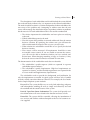
Over the past decade or so, the business world
has made much use, and sometime abuse, of
Thomas Kuhn's notion of "paradigm shift," which he describes in his 1963
landmark contribution to the history of science, The Structure of Scientific
Revolutions. It's hard to explain Kuhn's concept in a nutshell, but here
goes: Each historical era of scientific thought understands the world
according to accepted laws and ignores phenomena that those laws cannot
explain. Over time, the evidence for the unexplainable becomes so great
that new scientific laws accounting for those phenomena replace the old
ones. In a sense, "reality" changes, paving the way for innovations within
a new, revolutionary context. The shift to believing that theEarth orbits
the sun instead of vice-versa is a classic example; in fact, it's where our
more general sense of the word "revolution" comes from.
Kuhn's notion has been particularly appealing to the high-tech industry,
where a few true visionaries and most corporate leaders tout their latest
technologies as riding the wave of the latest "paradigm shift." By which
they mean, for example, the move to client/server computing, then n-tier
computing, then Internet and Web-based computing, e-commerce, and
now, presumably, Web Services and grid computing. The problem is, these
evolutions in computing architecture aren't really analogous to Kuhn's
theory of scientific revolutions. Reality hasn't changed so much as simply
sped up, and become increasingly distributed.
That's why we're delighted this month to publish Part I of a two-part
interview with one of the world's leading authorities in testing, Cem Kaner,
who has made good use of Kuhnian thought in his exploration of software
test design. As a consultant, he noticed strict limits to what one testing
organization would accept as valid, then similarly rigid but very different
limits (laws) in another organization. In Part I of this interview by
Rational's own testing guru, Sam Guckenheimer, Kaner describes his view
that a given context, like a paradigm, is an important shaper of test
design for different organizational realities. The second half of this
interview will appear in our August issue.
This month we also offer three articles that treat different aspects of
requirements management: Dean Leffingwell returns with a look at
requirements management in the context of agile development; Ben
Lieberman takes a close look at risk management and how corporate
culture and maturity can influence risk assessment; and two of Rational's
own requirements management authorities, Catherine Connor and Leonard
Callejo, provide lots of reasons not to leave RM strictly in the hands of
requirements analysts in "Requirements Management Practices for
Developers."
We also have an update from the experts at Forrester Research on the
latest trends in software for the consumer electronics market. Claire Cates
of SAS discusses how SAS implemented Rational Quantify and Purify to
improve its internal development environment. And there's a big excerpt
from the new book -- Use-Case Modeling -- by Rational use-case experts
and frequent Edge contributers Kurt Bittner and Ian Spence.
Be sure to consider the plusses and minuses of Joe Marasco's energizing
proposal in this month's "Franklin's Kite" column. The topic is especially
appropriate, given that this summer marks the 250th anniversary of
Benjamin Franklin's famous kite-in-the-thunderstorm experiment.
Happy iterations,
Mike Perrow
Editor-in-Chief
Copyright Rational Software 2002 | Privacy/Legal Information
Copyright Rational Software 2002
http://www.therationaledge.com/content/jul_02/f_interviewWithKaner_sg.jsp
An Interview with Cem Kaner, Software Testing
Authority
by Sam Guckenheimer
Senior Director of Technology for
Automated Test
Rational Software
Cem Kaner, Ph.D. J.D., is Professor
of Computer Sciences at Florida
Institute of Technology. He is perhaps
the world's most prolific and widely
read author, consultant, educator,
and attorney in the field of software
testing.
Last year, Dr. Kaner coauthored, with
James Bach and Bret Pettichord,
Lessons Learned in Software Testing:
A Context-Driven Approach. One of
his previous books, Testing Computer
Software (coauthored with Jack Falk
and Hung Nguyen), is a standard text
for training software testers. Many of
his articles on software testing are
available at www.kaner.com. In
addition, as an attorney, Dr. Kaner has been active in developing the law
of software quality, and he was elected to the American Law Institute in
recognition of his work.
Rational University recently engaged Dr. Kaner to develop content for a
new course, Principles of Software Testing for Testers. Dr. Kaner will teach
this course on August 17-18, immediately before the Rational User
Conference (RUC) in Orlando. (The course will be available from Rational
University instructors shortly afterwards.) At RUC, Dr. Kaner and his
coauthor James Bach will also deliver a talk on context-driven software
testing.
I recently had the pleasure of speaking with Dr. Kaner regarding the new
Rational course, his work on context-driven testing, his new book, his
curriculum development activities, and some of his foundational ideas in
software testing. I will share the highlights of that conversation with you
below.
Sam Guckenheimer: Let's start with your book Lessons Learned, which
you published about half a year ago. We liked the book so much we
featured part of it on Rational Developer Network. It's generated a lot of
interest, a lot of praise, and a little controversy. What drove you with
James Bach and Bret Pettichord to do Lessons Learned?
Cem Kaner: The three of us were pretty enthusiastic about some aspects
of the patterns movement. As I see it, the patterns movement involves a
structured writing style for taking well-understood learning and trying to
communicate it to other people. Although the structured style of writing in
patterns looks very easy -- you have a bunch of subheadings and you fill
in stuff for each one -- the method is time-consuming. And the essence of
what you have to say gets lost inside all of the other components in which
you don't have much special to say. I've done a lot of writing within
structured constraints. In the first edition of Testing Computer Software, I
tried to do something like that in the Appendix for bug descriptions, and
discovered that I could make a much better product -- and not hurt the
reader at all -- by focusing on the nugget of what I had to say and leaving
out the other details. So rather than writing a book called Patterns of
Software Testing, which came out of our first discussion, we said, Why
don't we just write a book called Lessons Learned? We would consider a
bunch of the things we had learned very well, extract the essence of
those, and instead of putting them into a structured form, put them down
one at a time and see what developed. Lessons Learned was the result.
SG: When you were creating Lessons Learned, did you set out to define
context-driven software testing based on context and forces in patterns, or
did it just emerge?
CK: The idea of context-driven testing had emerged in our group years
before. In fact, Brian Marick, James Bach, and I started writing a book in
1997 to define the context-driven school. We opened the software test
mailing list (http://groups.yahoo.com/group/software-testing/) specifically
as a home list for the context-driven school. We were talking about
context-driven testing a lot, but we were talking about it within an inner
circle and polishing our ideas before exposing them under that name to
the rest of the community. At some point during Lessons Learned, we
realized that Brian would be happy to have the three of us kind of
announce the school without his participation as a co-author. We were
hesitant about doing that, since he had done so much work in this area. In
any case, by the time we began work on the book, many of the contextdriven ideas were quite mature.
SG: How has the reception been to context-driven software testing?
CK: I think a lot of folks have responded that it's what they do anyway, so
while they're glad somebody is putting it into words, it's not really a big
deal. Other folks have found it liberating, and some have found it
intriguing; it's gotten them thinking. And some people are deeply offended
by it.
We're not surprised by the negative reactions. Many people in the testing
community feel there is "one right way" to do certain things. They know
the "right" lifecycle, the "right" test documentation method and test
techniques. And then we come along, saying, "You know, no technique is
good everywhere, and every technique is good somewhere, and the task is
to figure out when something will work and when it won't, rather than
whether it's good or bad." Some folks think that we're engaging in sloppy
thinking and are personally offended by it. Some consultants don't know
how to adapt their practices to include it, and simply attack it as
something different from what they've been teaching for many years.
SG: I'm curious about the earlier work you've done on paradigms of
testing which, of course, explores the notion that people have different
ways to do software testing and that all of these different schools claim
their method is the right one. Was that a driver behind context-driven
testing?
CK: The paradigm notion was, for me, a very important driver. That early
research was the first time that I had worked with anyone else to
crystallize some of the notions of context. The history of the paradigms is
kind of fun. When I was first breaking into consulting in the 1980s, I was
working full time but would do consulting at night and on weekends for
anybody desperate enough to hire me. You can imagine what sort of test
manager or development manager would be willing to give up a late
Saturday night to talk with a testing consultant. Those people were in
deep trouble.
I would, in those days, tell them about domain testing, using boundary
conditions, and about what I now call scenario testing, based on real-life
examples of how people use the product or how we would like to imagine
different users working with the product. And they would follow those
principles, things would get much better, and they would think I was a
genius -- and, of course, I thought I was pretty knowledgeable back then,
too. Then I became a full-time consultant and started selling my services
to people who weren't so desperate that they were willing to meet with me
at midnight. They expected me there at normal business hours, they
weren't in terrible trouble, and I would see them using methods that were
"wrong." I don't know how else to put it. Fortunately, before telling them
that everything they were doing was crazy, I had enough sense to ask for
access to their customer support database, and I would take a look at
what bugs they had in their bug tracking system and what complaints they
were getting from customers. This revealed what bugs they had found and
missed, and I realized that they had found things with their techniques
that would have been very hard for me to find. There were a few things I
had the ability to find that they had missed, but often, we simply had
different visions of what good testing was, and these visions were yielding
different, though quite effective, styles of testing.
Now, while these folks needed consulting -- they were certainly not as
effective as they wanted to be -- it was nevertheless remarkable how
much progress they could make following relatively few of the design
principles that I thought were basic. So I would take that company's ideas
and put them in my toolkit and go on to the next company, only to find
out they were doing something else that was different.
I had identified nine basic styles by the time I met James Bach at an
American Society for Quality meeting in Dallas. We had e-mailed for years,
and our first face-to-face meeting was extremely productive. We spent six
hours in the Dallas airport talking about test design. He pulled out a list of
nine basic testing styles, and lo and behold: They were the same as mine.
The names were slightly different, but they were the same. For each style,
we could name a company that relied almost exclusively on that style; if
you talked to them about some other style, they'd say, "that's not
testing," or "that's not interesting," or "that reveals bugs that nobody
cares about."
As we further discussed these nine styles of testing, we agreed that the
phenomenon looked very much like what Thomas Kuhn described in The
Structure of Scientific Revolutions as pre-scientific paradigms. A paradigm
really defines your scientific worldview. You have a set of data, you have a
theory associated with those data, and you have measurement techniques
or experimental techniques that are considered useful for finding new
research results. Plus, you have a bunch of unanswerable questions that
are out of scope relative to what you're currently working on and what you
expect to continue working on within your field. All fields of science, over
time, undergo revolutions in the ways problems are identified and
resolved. Problems that used to be considered out of scope eventually
offer an entirely new way of looking at the field. Practitioners start viewing
those previously uninteresting and out-of-scope issues as central to the
field of study. Bach and I both had had the experience of persuading
people to adopt one or two new testing styles in their company and
watching a transformation in their attitude about certain kinds of problems
and test methods. So we started working on ways to communicate our
style list to others.
Now, as soon as you come up with the notion that there are styles that
overlap but are far from completely overlapping, you end up asking the
question: If I were aware of all or most of these styles, how would I know
when to use one or the other? What's the cost-benefit associated with one
versus another? And you get into absolute contextual reasoning at that
point. You have to ask questions like: What are the skill sets of the people
who are doing this? What are the quality standards of people who have
influence over development?
Quality standards are a funny thing, by the way. I was at Electronic Arts
when we built Chuck Yeager's Flight Simulator. When I talk about context
sometimes, I contrast EA's simulator with the kind that the Air Force
would use. I point out that good testing for the Boeing flight simulator
would be very different from good testing for the Chuck Yeager simulator.
The response I often get back is, of course, that it would have been fine
for the game flight simulator to be of lower quality, so we can use less
rigorous approaches. But they miss the point. It's not that the
entertainment Flight Simulator is of a lower quality -- it's of a different
quality.
In a flight simulator game, it doesn't matter if the cockpit is shown
perfectly accurately. What matters is that somebody who has never flown
an airplane can have fun dealing with a very complex virtual instrument.
And if they can experience some of the thrill of flying without having to go
through pilot training, then you have a game that might be not only
commercially successful, but also entertaining in the best sense of the
word. Boeing doesn't have to worry about making their simulator fun.
Instead, they have to make their simulator absolutely realistic and
structure it so that it will operate properly under all sorts of circumstances
that test pilots are going to face. A kid crashing the game flight simulator
has a very different emotional experience from a pilot crashing a training
flight simulator. We don't have to worry as much about game players
crashing; in fact, for some folks that's fun. We do have to worry about the
screen being absolutely predictable and grouping the game controls in
ways that novices will find appropriate. So the quality standards we used
to create the game simulator at Electronic Arts were not necessarily higher
or lower than the quality standards at Boeing, but the quality criteria -playability, entertainment value, educational value -- are very different
from the criteria for an Air Force flight simulator -- which are based on
getting someone ready to fly a plane accurately and skillfully.
So the test techniques that you're going to use for the two flight
simulators will really be very different, and at the end you will have two
incredibly different products. The testers of one product might not be in
any way competent to test the other product, but both products might still
be absolutely successful and well respected. That's one of the best
illustrations of context-driven testing that I can think of.
SG: You talk about this kind of spread in the Principles of Software Testing
for Testers course as well. If an organization is like those you mentioned
earlier - married to one kind of testing style but really should be using
others too -- what does it take to get them to see the benefit?
CK: Generally, they have to notice that they are missing problems or
spending too much finding the problems that they do find. Often it takes a
crisis, like costly recalls that are visible to senior management. Sometimes
the frustration comes from slow response time. If your product is really
taking off and getting used under an increasingly wide range of
circumstances out in the field, customers will encounter problems under
the new usage conditions. If your testing style requires a long time to
develop and document tests, you won't be able to keep up with all the
problems and their fixes. Some test groups notice that their programmers
and tech support staff catch the problems before they become disasters.
But when you see problems caught by programmers or customer support
that should have been caught by testers, you know it's only a matter of
time before some problems will be missed by two or three levels of folks,
and you're at great risk of serious failures or recalls. That's when people
start thinking, Hmmm, maybe we need to do our testing a little differently
than we've been doing it.
SG: The course that you helped Rational with, of course, covers all of the
approaches. Would you say that the most important take-away from the
course is the ability to appreciate new approaches to testing and take
home ideas for new ones you can try?
CK: Actually, I think the Rational course offers several valuable things.
Certainly laying out several different test techniques should be of value to
anyone who takes the course. We also spend a lot of time on
communication, on problem reporting.
I think that problem reporting is among the most fundamental skills that
testers can have, yet it's among the least well-practiced. Rational
publishes an excellent problem tracking tool, but if someone doesn't know
what to write, then a well-structured database only helps them put stuff in
that no one will read. Imagine that, when you discover a bug, someone
other than you has to make an informed business decision about whether
to fix it or even do follow-up research on it. Your goal, as a tester, is to
give that person the best information they can have to make that
decision; in some cases, that means pushing them pretty hard with data
to get them to understand how serious the problem is, so they'll make a
decision to go for higher quality even on a tough schedule or at a high
cost. Under these circumstances, you need techniques to make the
severity of the problem more clear, to make the circumstances under
which the problem appears simpler to explain and imagine, and to make
the presentation itself easier to read. In the Rational course, we drill these
techniques, and I think that's a very important thing for testers.
I did a study at one company across six of their products, looking partly at
the question of why certain bugs had escaped into the field and caused
recalls. As I wandered through their bug tracking results, what struck me
most was that they had many testers who were not writing really good
problem reports. This came as a surprise to the company. They had such
confidence that their engineers would fix problems if they understood
them, that many testers felt that all they ad to do was to get a problem to
the point where it was reproducible and write a description that was
accurate. But too often, the descriptions were rambling, over-detailed, and
not necessarily focused on the problem's effect on a customer or another
stakeholder. By looking at the readability and focus of the report, I was
able to predict whether a reported problem was likely to be fixed or not. I
think many companies overlook very serious problems just because their
tracking reports are weak. Programmers reading those reports would
probably tend to turn their attention to fixing much less serious problems
simply because their descriptions were easier to understand. So I think
effective reporting is a fundamental skill for testers -- to be able to take
what they learn through testing and communicate it very well in writing.
Coming next month: Part II of this series, with a focus on education and
training for software testers.
Want to learn more from Cem Kaner himself about the testing
issues, styles, and techniques discussed in this interview? Sign up
now for the RUC Pre-Conference Training session Principles of
Software Testing!
For more information on the products or services discussed in this
article, please click here and follow the instructions provided.
Thank you!
Copyright Rational Software 2002 | Privacy/Legal Information
Copyright Rational Software 2002
http://www.therationaledge.com/content/jul_02/f_agileRequirements_dl.jsp
Agile Requirements Methods
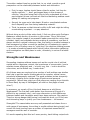
by Dean Leffingwell
Software Entrepreneur and
Former Rational Executive
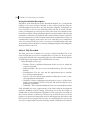
To ensure that their software teams
build the right software the right
way, many companies turn to
standard processes such as Rational
Software's Rational Unified Process®
(RUP®), a comprehensive set of
industry best practices that provide
proven methods and guidelines for
developing software applications.
Through the application of use cases
and other requirements techniques,
the RUP helps development teams
build the right software by helping
them understand what user needs their products must fulfill. Moreover,
the RUP and many other contemporary software processes prescribe a
software lifecycle method that is iterative and incremental, as this method
helps teams address the risk inherent in a new development effort more
effectively than did earlier, more rigid "waterfall" process approaches. Risk
can originate from a variety of sources: technology and scale, deficient
people skills, unachievable scope or timeline issues, potential health or
safety hazards defects, and so on. Experience has proved repeatedly that
addressing these risks early in the lifecycle is a key factor in producing
successful project outcomes, and requirements management is one very
effective way to accomplish this.
Mitigating Requirements Risk with Effective
Requirements Practices
In our book Managing Software Requirements: A Unified Approach,1 Don
Widrig and I described a comprehensive set of practices intended to help
teams more effectively manage software requirements imposed on a
system under development. As the systems teams are building today can
be exceedingly complex, often comprising hundreds of thousands or even
millions of lines of code, and tens to hundreds of person-years in
development time, it makes sense that requirements themselves are also
likely to be exceedingly complex. Therefore, a significant variety of
techniques and processes -- collectively a complete requirements
discipline -- are required to manage requirements effectively.
But lest we lose sight of the purpose of software development, which is to
deliver working code that solves customer problems, we must constantly
remind ourselves that the entire requirements discipline within the
software lifecycle exists for only one reason: to mitigate the risk that
requirements-related issues will prevent a successful project outcome. If
there were no such risks, then it would be far more efficient to go straight
to code and eliminate the overhead of requirements- related activities.
Therefore, when your team chooses a requirements method, it must
reflect the types of risks inherent in your environment. Each of the
requirements techniques we describe in our book, as well as those
recommended in the RUP, was developed solely to address one or more
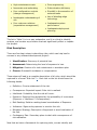
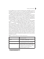
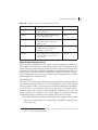
specific types of requirements-related risks. Table 1 summarizes these
techniques, along with the nature and type of risks that each is intended
to mitigate.
Table 1: Requirements Techniques Address Specific Project Risks
Technique
Risk Addressed
Interviewing
- The development team might not understand who
the real stakeholders are.
- The team might not understand the basic needs of
one or more stakeholders.
Requirements Workshops
- The system might not appropriately address classes
of specific user needs.
- Lack of consensus among key stakeholders might
prevent convergence on a set of requirements.
Brainstorming and Idea Reduction
- The team might not discover key needs or
prospective innovative features.
- Priorities are not well established, and a plethora of
features obscures the fundamental "must haves."
Storyboards
- The prospective implementation misses the mark.
- The approach is too hard to use or understand, or
the operation's business purpose is lost in the planned
implementation.
Use Cases
- Users might not feel they have a stake in the
implementation process.
- Implementation fails to fulfill basic user needs in
some way because some features are missing or
because of poor usability or error and exception
handling, etc.
Vision Document
- The development team does not really understand
what system they are trying to build, or what user
needs or industry problem it addresses.
- Lack of longer term vision causes poor planning and
poor architecture and design decisions.
Whole Product Plan
- The solution might lack commercial elements
necessary for successful adoption.
Scoping Activities
- The project scope exceeds the time and resources
available.
Supplementary Specification
- The development team might not understand nonfunctional requirements: platforms, reliability,
standards, and so on.
Trace Use Cases to Implementation - Use cases might be described but not fully
implemented in the system.
Trace Use Cases to Test Cases
- Some use cases might not be tested, or alternative
and exception conditions might not be understood,
implemented, and tested.
Requirements Traceability
- Critical requirements might be overlooked in the
implementation.
- The implementation might introduce requirements
or features not called for in the original requirements.
- A change in requirements might impact other parts
of the system in unforeseen ways.
Change Management
- New system requirements might be introduced in an
uncontrolled fashion.
- The team might underestimate the negative impact
of a change.
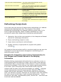
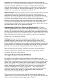
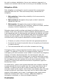
Methodology Design Goals
As we have said, the purpose of requirements methodology is to address
requirements-related project risks. The purpose of the overall
development methodology is to address collective project risks. In his
book on agile development, Alistair Cockburn identifies four major
principles to apply when designing and evaluating methodologies:
1. Interactive, face-to-face communication is the cheapest and fastest
channel for exchanging information.
2. Excess methodology weight is costly.
3. Larger teams need heavier methodologies.
4. Greater ceremony is appropriate for projects with greater
criticality.2
Let's examine these principles briefly to see what insight we can gain into
selecting the correct requirements management methodology for a
particular project context.
Principle #1: Interactive, Face-to-Face Communication Is
the Cheapest and Fastest Channel for Exchanging
Information
Whether eliciting requirements information from a customer or user, or
communicating that information to a team, face-to-face is the best and
most efficient way to communicate. If the customer is close to the team
and directly accessible, if the customer can explain requirements directly
to the team, and if the analyst can communicate directly with the
customer and the team, then less documentation is needed3 -- although
critical requirements must still be documented. Otherwise, there is a
danger that the tacit assumption "We all know what we are developing
here" may become a primary risk factor for the project team. But certainly
the team can get by with fewer, highly necessary documents -- Vision
documents, use cases, supplementary specs, and the like -- and these can
be shorter and less detailed.
Principle #2: Excess Methodology Weight Is Costly
This principle translates to: "Do only what you have to do to be
successful." Every unnecessary process or artifact slows the team down,
adds weight to the project, and diverts time and energy from essential
coding and testing activities. The team must balance the cost and weight
of each requirement activity with the risks listed in Table 1. If a particular
risk is not present or likely, then consider deleting the corresponding
artifact or activity from your process. Alternatively, think of a way to
"lighten" the artifact until it's a better fit for the risk in your particular
project. Write abbreviated use cases, apply more implicit traceability, and
hold fewer reviews of requirements artifacts.
Principle #3: Larger Teams Need Heavier Methodologies
Clearly an appropriate requirements methodology for a team of three
developers who are subject matter experts and who have ready access to
a customer may be entirely different than the right methodology for a
team of 800 people at five different locations who are developing an
integrated product line. What works for one will not work for the other.
The requirements method must be scaled to the size of the team and the
size of the project. However, you must not overshoot the mark either, as
an over-weighted method will result in lower efficiency for a team of any
size.
Principle #4: Greater Ceremony Is Appropriate for Projects
with Greater Criticality
The criticality of the project may be the greatest factor in determining
methodology weight. For example, it may be quite feasible to develop
software for a human pacemaker's external programming device with a
two- or three-person coding team. Moreover, the work would likely be
done by a development team with some subject matter expertise as well
as ready access to clinical experts who can describe exactly what
algorithms must be implemented. However, on such a project, the cost of
even a small error might be quite unacceptable, and even entail loss of
human life. Therefore, all the intermediate artifacts that specify the use
cases, algorithms, and reliability requirements must be documented in
exceptional detail, and they must be reviewed and vetted as necessary to
ensure that only the "right" understanding appears in the final
implementation. In such cases, therefore, a small team would need a
heavyweight method. And conversely, a non-critical application with
sufficient scope to require a larger team might very well be able to use a
lighter method.
Documentation Is a Means to an End
Most requirements process artifacts, Vision documents, use cases, and so
forth -- and indeed most software development artifacts in general,
require non-code documentation of some kind. Given that these
documents divert time and attention from essential coding and testing
activities, a reasonable question to ask with respect to each one is: "Do
we really need to write this document at all?"
You should answer "Yes" only if one or more of these four criteria apply:
1. The document communicates an important understanding or
agreement for instances in which simpler, verbal communication is
either impractical (larger or more distributed team) or would create
too great a project risk (pacemaker programmer device).
2. The documentation allows new team members to come up to speed
more quickly and therefore renders both current and new team
members more efficient.4
3. Investment in the document has an obvious long-term payoff
because it will evolve, be maintained, and persist as an ongoing
part of the development, testing, or maintenance activity. Examples
include use case and test case artifacts, which can be used again
and again for regression testing of future releases.
4. A requirement for the document is imposed by some company,
customer, or regulatory standard.
Before including a specific artifact in your requirements method, your
team should ask and answer the following two questions (and no, you
needn't document the answers!).
●
●
Does this document meet one or more of the four criteria above? If
not, then skip it.
What is the minimum level of specificity that can be used to satisfy
the need? If you do not need the level the project calls for, then
either do not use it, or use an abbreviated version.
With this perspective in hand, let's move on to defining a few
requirements approaches that can be effective in particular project
contexts. We know, or course, that projects are not all the same style and
that even individual projects are not homogenous throughout. A single
project might have a set of extremely critical requirements or critical
subsystems interspersed with a larger number of non-critical requirements
or subsystems. Each element would require a different set of methods to
manage the incumbent risk. So a bit of mixing and matching will be
required in almost any case, but we can still provide guidelines for
choosing among a few key approaches.
An Extreme Requirements Method
In the last few years, the notion of extreme programming as originally
espoused by Beck5 has achieved some popularity (along with a significant
amount of notoriety and controversy). One can guess at what has
motivated this trend. Perhaps it's a reaction to the inevitable and
increasing time pressures of an increasingly efficient marketplace, or a
reaction to the overzealous application of otherwise effective
methodologies. Or perhaps it's a reaction to the wishes of software teams
to be left alone to do what they think they do best: write code. In any
case, there can be no doubt of the "buzz" that extreme methods have
created in software circles, and
Three Points to Remember About
that the "agile methods"
Method
movement is now creating, as it
attempts to add balance and
●
The purpose of the software
practicality to the extreme
development method is to
approach. Let's look at some of
mitigate risks inherent in the
the key characteristics of XP and
project.
then examine how we might define
an Extreme Requirements Method
●
The purpose of the
that would be compatible with this
requirements management
approach.
method is to mitigate
requirements-related risks on
the project.
1. The scope of the application
or component permits
●
No one method fits all
coding by a team of three to
projects; therefore the
ten programmers working at
requirements method must be
one location.
tailored to the particular
project.
2. One or more customers are
on site to provide constant
requirements input.
3. Development occurs in frequent builds, or iterations, each of which
is releasable and delivers incremental user functionality.
4. The unit of requirements gathering is the "User Story," a chunk of
functionality that provides value to the user. User stories are
written by customers on site.
5. Programmers work in pairs and follow strict coding standards. They
do their own unit testing and are supposed to provide constant
refactoring of the code to keep the design simple.
6. Since little attempt is made to understand or document future
requirements, the code is constantly re-factored (redesigned) to
address changing user needs.
Let's assume you have a project scope that can be achieved by a small
team working at one location. Further, let's assume that it's practical to
have a customer on site during the majority of the development (an
arrangement that is admittedy not very practical in most project contexts
we've witnessed). Now, let's look at XP from the standpoint of
requirements methods.
A key tenet of any effective requirements method is early and continuous
user feedback. When looked at from this perspective, perhaps XP doesn't
seem so extreme after all. Table 2 illustrates how some key tenets of XP
can be used to mitigate requirements risks we've identified so far.
Table 2: Applying XP Principles to Requirements Risk Mitigation
XP Principle
Mitigated Requirements Risk
Application or component scope is
such that the coding can be done by
three to ten programmers at one
location.
Constant informal communication can minimize or
eliminate much requirements documentation.
One or more customers are on site
to provide constant requirements
input.
Constant customer input and feedback dramatically
reduces requirements-related risk.
Development occurs in frequent
builds, or iterations, each of which is
releasable and delivers incremental
user functionality.
Customer value feedback is almost immediate; this
ship can't go too far off course.
The unit of requirements gathering is
the "User Story," a chunk of
functionality that provides value to
the user. User stories are written by
customers on site.
A use case is "a sequence of events that delivers
value to a user." Can user stories and use cases be
all that different? If users contribute to both of
them, then how far apart can they be?
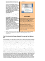
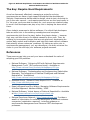
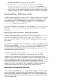
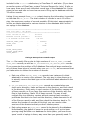
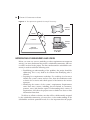
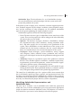
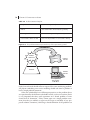
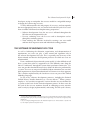
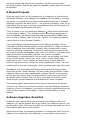
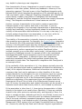
With this background, let's see if we can derive a simple, explicit
requirements model that would reflect or support an XP process. Perhaps
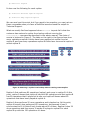
it would look like Figure 1 and have the following characteristics.
Figure 1: Extreme Programming Requirements Model
Concept. At the heart of any requirements process lives the product
concept. In this case, the concept is communicated directly from the
customer to the project team -- verbally, frequently, and repeatedly as
personnel change.
Vision. As explained in Managing Software Requirements6 and in the RUP,
the Vision carries the product concept, both short term and long term. A
"Delta Vision document" typically describes the new features and use
cases to be implemented in a specific release. In XP, this document may
not exist. We are dependent on the customer's ability to tell us what the
product needs to do now, and what it needs to do later, and we are
dependent on the development team to make the right architectural
decisions now -- for both now and later. Whether or not this can be made
to work in practice depends on a number of project factors and the
relative risks the team is willing to take; you can't say for certain that it
couldn't work, at least for some project scenarios.7 So we'll leave this
artifact out of our extreme requirements method.
Requirements. Another principal tenet of our text and the RUP is that the
use-case model carries the majority of functional requirements. It
describes who uses the system and how they use it to accomplish their
objectives. XP recommends the use of simple "stories" that are not unlike
use cases, but perhaps shorter and at a higher level of abstraction.
However, we recommend that there always be a use-case model, even if
it's a simple, non-graphical summary of the key user stories that are
implemented and what class of user implements them. We'd insist on this
use-case model, even for our extreme method.
Supplementary Spec/Non-Functional Requirements. XP has no
obvious placeholder for these items, perhaps because there are not very
many, or the thinking is that they can be assumed or understood without
mention. Or perhaps customers communicate these requirements directly
to programmers whose work is affected by them. Seems a bit risky, but if
that's not where the risk lies on your project, so be it; we'll leave this
artifact out of our extreme method.
Tooling. The tools of XP are whiteboards and desktop tools, such as
spreadsheets with itemized user stories and priorities, and so forth.
However, defects will naturally occur, and although XP is quiet on the
tooling subject, let's assume we can add a tracking database of some kind
to keep track of all these stories: perhaps their status, as well as defects
that will occur and must be traded off with future enhancements.
With these simple documents, practices, and tools, we've defined an
extreme requirements method that can work in appropriate, albeit
somewhat extreme, circumstances.
An Agile Requirements Method
But what if your customer can't be located on site? What if you are
developing a new class of products for which no current customers exist?
What if the concepts are so innovative that customers can't envision what
stories they would fulfill? What if your system has to be integrated with
either new systems or other existing systems? What if more than ten to
twenty people are required? What if your system is so complex that it
must be considered as a "system of systems" -- with each system
imposing requirements on others? What if some of your team members
work from remote sites? What if a few potential failure modes are
economically unacceptable? What then?
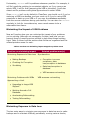
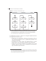
Then you will need a more robust method. One that can address the
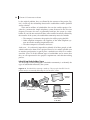
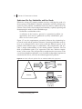
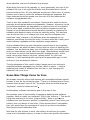
additional risks in your project context. Then you will need a method that
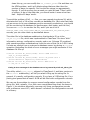
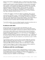
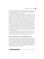
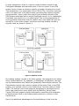
looks more like the agile method depicted in Figure 2.
Figure 2: An Agile Requirements Approach
Concept. In the agile method, the root of the project is still the concept,
but that concept is tested and elaborated by a number of means, including
requirements workshops or interviews with prospective customers.
Vision. The Vision is no longer only verbal; it is defined incrementally in
the Delta Vision document which describes the new features and use cases
to be implemented in a specific release. The whole product plan describes
the other elements of your successful solution: the commercial and
support factors, licensing requirements, and other factors that are keys to
success.
Requirements. The use-case model diagram defines the use cases at the
highest level of abstraction. In addition, in this more robust method, each
use case has a specification that elaborates the sequence of events, the
pre- and post-conditions, and the exceptions and alternative flows. The
use-case specifications will likely be written at differing levels of detail.
Some areas are more critical than others; other areas are more innovative
and require further definition before coding begins. Still other areas are
straightforward extensions to known or existing features and need little
additional specification.
Supplementary Spec/Non-Functional Requirements. Your application
may run on multiple operating systems, support multiple databases,
integrate with a customer application, or have specific requirements for
security or user access. Perhaps external standards are imposed upon it,
or a host of performance requirements that must be individually identified,
discussed, agreed to, and tested. If so, then the supplementary
specification contains this information, and it is an integral artifact to an
agile software requirements management method.
Tooling. As the project complexity grows, so do the tooling requirements,
and the team may find it beneficial to add a requirements tool for
capturing and prioritizing the information or automatically creating a usecase summary from the developed use cases. And the more people that
work on the project, and the more locations they work from, the more
important version control becomes, both for the code itself and for the use
cases and other requirements artifacts that define the system being built.
Well now, with some practical and modest extensions to our extreme
method, we've now defined a practical and agile requirements method,
one that is already well proven in a number of real world projects.
A Robust Requirements Method
But what if you are developing the pacemaker programmer we described
above? What if your teams are developing six integrated products for a
product family that is synchronized and released twice a year? You employ
800 developers in six locations worldwide, and yet your products must
work together. Or what if you are a telecommunications company, and the
success of your company will be determined by the success of a thirdgeneration digital switching system that will be based on the efforts of
thousands of programmers spanning a time measured in years? What
then? Then you will need a truly robust requirements method. One
that scales to the challenge at hand. One that can be tailored to deliver
extremely reliable products in critical areas. One that allows developers in
other countries to understand the requirements that are imposed on the
subsystem they are building. One that can help assure you that your
system satisfies the hundreds of use cases and thousands of functional
and nonfunctional requirements necessary for your application to work
with other systems and applications -- seamlessly, reliably, and flawlessly.
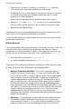
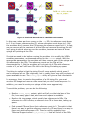
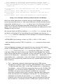
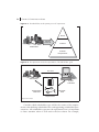
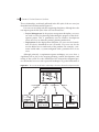
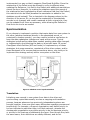
So now, we come full circle to the robust requirements management
method expressed in Figure 3.
Figure 3: A Robust Requirements Management Method
Concept. Given the complexity of the application itself, and the likelihood
that few, if any, features can actually be implemented and released before
a significant amount of architectural underpinnings are developed and
implemented, we want to add a range of concept validation techniques.
Each will bring us closer to our goal of understanding the intended
behavior of the system we are about to build.
Vision. In order to assure understanding amongst a large number of
stakeholders, developers, and testers, the Vision, both near term and
longer term, must be documented. It must be sufficiently long-range for
the architects and designers to design and implement the right
architecture to support current and future features and use cases. The
whole product plan should be extended to describe potential variations in
purchase configurations and likely customer deployment options. The plan
should also define supported revision levels of compatible applications.
Requirements. The use cases are elaborated as necessary so that
prospective users can validate the implementation concepts. This ensures
that all critical requirements will be implemented in a way that helps
assure their utility and fitness. Because the application is critical, all
alternative sequences of events are discussed and described. Pre-and postconditions are specified, and are as clear and unambiguous as possible.
Additional, more formal techniques -- analysis models, activity diagrams,
message sequence diagrams -- are used to describe more clearly how the
system does what it does, and when it does it.
Supplementary Spec/Non-Functional Requirements. The
supplementary specification is as complete as possible. All platforms,
application compatibility issues, applicable standards, branding and
copyright requirements, and performance, usability, reliability, and
supporting requirements are defined.
Tooling. Larger, more distributed teams require industrial strength
software tooling. Analysis and design tools further specific system
behavior, both internal and external. Multi-site configuration management
systems are employed. Requirements tools support requirements
traceability from features through use cases and into test cases. The
defect tracking system extends to support users from any location.
Project Control. Larger projects require higher levels of project support
and control. Requirements dashboards are built so that teams can monitor
and synchronize interdependent use-case implementations. A Change
Control Board is constituted to weigh and take decisions upon possible
requirements additions and defect fixes. Requirements analysis and impact
assessment activities are performed to help understand the impact of
proposed changes and additions.
Taken together, these techniques and activities in our robust requirements
management method help assure that this new system -- in which many
tens or hundreds of man years have been invested and -- which will touch
the lives of thousands of users across the globe -- is accurate, reliable,
safe, and well suited for its intended purpose.
Summary
In this article, we've reinforced the concept that the project methodology
is designed solely to assure that we mitigate the risks present in our
project environment. Too much methodology and we add overhead and
burden the team with unnecessary activities. If we aren't careful, we'll
become slow, expensive, and eventually uncompetitive. Some other team
will get the next project, or some other company will get our next
customer. Too little methodology, and we assume too much risk on the
part of our company or our customers, with perhaps even more severe
consequences.
To manage this risk, we've looked at three prototypical requirements
methods: an extreme requirements method, an agile requirements
method, and a robust requirements method, each of which is suitable for a
particular project context. And yet we recognize that every project is
unique, and every customer and every application is different; therefore,
your optimal requirements method will likely be none of the above.
Perhaps itwill be some obvious hybrid, or perhaps a variant we did not
explore. But if you are properly prepared, then you can select the right
requirements method for your next project.
References
Rational Unified Process 2001. Rational Software Corporation, 2001.
Dean Leffingwell and Don Widrig, Managing Software Requirements: A
Unified Approach. Addison-Wesley, 1999.
Kent Beck, Extreme Programming Explained: Embrace Change. AddisonWesley, 2000.
Alistair Cockburn, Agile Software Development. Addison-Wesley, 2002.
Notes
1
Dean Leffingwell and Don Widrig, Managing Software Requirements: A Unified Approach.
Addison-Wesley, 1999.
2
Alistair Cockburn, Agile Software Development. Addison Wesley, 2002, pp. 149-153.
3
It is important to take this notion with a grain of salt. As Philippe Kruchten points out, "I
write to better understand what we said."
4
In our experience, this issue is often overrated, and the team may be better off focusing
new members on the "live" documentation inside the requirements, analysis and design
tools, and so forth.
5
Kent Beck, Extreme Programming Explained: Embrace Change. Addison-Wesley, 2000.
6
Leffingwell and Widrig, Op.Cit.
7
As we said, the method is not without its critics. One reviewer noted the big drawback of
the "one user story at a time," is the total lack of architectural work. If your initial
assumption is wrong, you have to re-factor architecture one user story at a time. You build a
whole system, and the n-1th story is, "OK, this is fine for one user. Now, let us make it work
for 3,000."
For more information on the products or services discussed in this
article, please click here and follow the instructions provided.
Thank you!
Copyright Rational Software 2002 | Privacy/Legal Information
Copyright Rational Software 2002
http://www.therationaledge.com/content/jul_02/f_electronicsAndDevelopment_sc.jsp
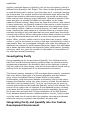
Software Development for Consumer
Electronics:
Bigger, Better, Faster, More -- Or Bust
An Interview with Josh Bernoff, Forrester Research; and Jed
Kolko, Forrester Research
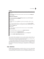
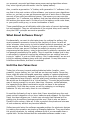
Success in the consumer electronics (CE)
industry has always revolved around
hardware innovations. But as products
become more complex and feature rich, it
is the design and function of softwaredriven interfaces that increasingly
differentiate the players and determine the
winners.
Software developers still face all the
challenges you'd expect in a market where
nearly every application is embedded and
must be as fast, cheap, proven, and
modular as possible. Development cost is
also a major factor in profitability,
especially in commodity categories such as
VCRs and televisions, where margins are slim.
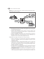
But perhaps the most significant trend in consumer electronics today,
particularly from the standpoint of software engineering, is the
accelerating need to integrate devices -- from cell phones to cameras -with PCs, the Internet, and other technologies. Indeed, ease of
connectivity can be the deciding factor in a product's acceptance. Bringing
a well-designed, well-connected product to market at warp speed requires
a shared vision and a well-coordinated process encompassing all the
players on the team: hardware engineers, software developers, product
designers, and market researchers.
To learn more about how changes in the consumer electronics business
are impacting software development, reporter Scott Cronenweth
interviewed two industry experts at Forrester Research: Josh Bernoff,
Principal Analyst, and Jed Kolko, Senior Analyst. Bernoff currently
specializes in the television marketplace and has broad expertise on the
supply side of consumer electronics; Kolko focuses on the demand side,
through his research on consumer devices, access, and services.
SC: What are the key factors that determine success in the
consumer electronics marketplace? Getting an innovative product
to market first? Pricing? Gee-whiz features? Usability?
Interoperability with the PC?
JB: There are really only two strategies for success in consumer
electronics. One is to get a new product out before anyone else and then
defend your market leadership position. You can command a
comparatively high price for your product by going after early adopters.
The trouble is, however, that in this extremely competitive environment,
any worthwhile advance generally gets copied pretty quickly.
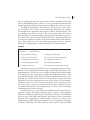
So the second strategy
is to be a fast follower.
In the long run, most of
the money ends up
being made by the
Toshibas and Sonys of
the world coming in on
the heels of the early
leaders and producing
products that have
either some special design feature or a lower price tag. Those companies'
success rests on having the cheapest manufacturing and prodigious
distribution strength. To achieve economies of scale you need global reach
and global manufacturing capability, and you have to get into the right
stores. Unless you're in Circuit City and Best Buy you're unlikely to
succeed in consumer electronics.
The upshot is that, by and large, products in the same category are very
similar to each other. When this happens, buyers become very sensitive to
price, and they pay less attention to what company label is on the product.
Cost is especially important at the lower end of a given market. Design
and look-and-feel -- the way the remote control looks; the way it feels in
your hand if it's a portable device -- are important differentiators at all
price points.
SC: Let's go back to what's required to succeed with that first
strategy. How do you capture those early adopters if you have an
innovative product?
JK: What we consistently find in our research is that the most successful
product launches happen when consumers are presented with reasonable
expectations and basic applications.
If a consumer is not comfortable using the keypad on her cell phone to
send a quick message, then she will not have the experiential background
to comfortably embrace SMS (short message services) or wireless instant
messaging, or to get excited by an ad campaign around mobile commerce
or video conferencing. This critical need to focus on what consumers really
want makes it imperative that organizations establish clear, ongoing
communication and a shared, clearly understood vision across their
marketing and development functions in the design, development, and
introduction of a new product. Otherwise, consumers may fail to adopt
even well-designed offerings.
In introducing wireless technology for cars, for example, the telematics
industry has wisely focused first on emergency assistance and other very
basic safety and security features. As opposed to trying to hype real-time
traffic reports and automatic trip calculations, which don't even really exist
yet. What's currently going on in the home networking arena will be an
interesting test case. The hype there now is "Get broadband, get a home
network, and soon your PC will be talking to your washing machine." The
right message is "If you get a home network, then multiple PCs in your
house can share a broadband connection." This is a very straightforward
application of the technology, but one that resonates with a need
consumers have -- and are aware of -- now. Few people really care about
the sexy-but-impossible applications.
SC: The logic of what you're saying seems almost beyond debate.
So why are straightforward value propositions so hard to come by
in the marketplace?
JK: I think it's simply that marketing and market research teams on one
hand, and design and core product development teams on the other hand,
represent two very different cultures and viewpoints. Engineers focus on
creating a device that incorporates cutting edge technology and provides
the best solution to a problem. Whereas the marketing team is focused on
the more mundane factors that drive a consumer toward a new technology
-- or keep them away from it. Because most product developers and
designers are accustomed to pushing the limits of technology, it's naturally
rather easy for them to lose sight of the pragmatic reasons why
consumers either adopt or don't adopt the technology.
For instance, many consumers hesitate going to broadband because they
don't want to give up the e-mail address that they have with their dial-up
service provider. All the technological improvements in the world won't get
consumers to make the shift if their main concern is the hassle of telling
all their friends they have a new e-mail address. Now that's way below the
development radar screen! But factors like these are often on the minds of
the marketers whose job it is to put themselves in consumers' shoes. The
key is to communicate and maintain a common goal and a coherent
business model for the product as it goes to market. That's a step that
product teams sometimes gloss over, and that can spell disaster.
Figuring out the requirements for a product should begin with figuring out
what's important to your potential customers. The issue isn't a lack of
features; it's a lack of usability. A lot of developers rightly focus on the
most extreme possibilities for a new technology. But marketing has to
counterbalance that bias; its focus should on the less glamorous
capabilities that will actually get consumers to buy the product.
Take a look at the Palm Pilot. It succeeded in a category where all the
previous products, like the Newton, had flopped completely. Why? First,
the original concept of what would appear on the screen, and where the
buttons would be, was extremely well thought out. Second, it was tested
and refined for ideal usability, so people liked it immediately. If you follow
a new product vision completely in your own head, then you're probably
not going to understand everything that users want. But if you have a
brilliant idea and you combine it with the testing that's required to really
refine it, then you'll succeed.
JB: At Forrester we see examples all the time of new products that do
things nobody's ever seen before, that were engineered very creatively,
and that fall flat on their faces. And in many cases it's because they do
something that people don't want. Like the WebTV viewer,1 which doesn't
particularly appeal to that many people. But it's more frequently the case
that a product flops because its design is so clunky that it's a major
challenge for people to figure out how to use it. The ZapStation2 comes to
mind in that category.
One of the insights that we found really instructive came from a report I
co-authored at the end of last year called The Secret to Device Success.
We looked at MP3 players, digital cameras and PDAs (personal digital
assistants), comparing their interfaces and their overall usability. What
became abundantly clear was that the ability of these kinds of devices to
connect in a rational way to the PC was hugely important in their success.
And you can readily see that all three of those product types succeed or
fail in many ways based on how easy it is to connect them to the PC and
copy or move information back and forth.
In that comparative context, one can also cite examples of products that
seemed to have been introduced too early, before the company really
understood the usability issues they needed to address. And a product
that's inferior from a usability standpoint in any of those spaces is simply
not competitive. I think the lesson here is that the design and features
have to add up to making usability effortless -- which is what it really
takes to be successful. And as hardware designers hand things off to the
software designers, you have to ensure that the focus on usability is not
lost.
SC: So how does this need for effortless usability, along with all
the market pressures you mentioned --- for rapid introduction,
rapid innovation, low cost -- impact the people who develop
software for consumer electronic devices?
JB: Consumer electronics today is a challenging environment for
developers, obviously. The software that runs in these products is almost
always embedded, and the bottom-line goal is to make it as small and
cheap as possible. Modularity is also increasingly important: If you can't
drop in and reuse components, then you won't make it to market quickly,
and your costs will go up. A component-based architecture also makes it
easier for you to refine the design or the interface of a device in response
to usability testing or other market research.
Then add new levels of complexity to the equation. Software in CE devices
used to consist of little more than the enabling layer that drives things like
the display that appears when you hit the Volume Up key on your
television remote. But that's changing rapidly as we see more and more
sophisticated products like a TiVo or a cable set-top box. There's some
relatively advanced stuff going on in there. Inside the TiVo, for example, is
Linux.
By far the most important driver for increased software complexity,
however, is the value consumers perceive in being able to connect a
device to your PC or to something on the Internet. ReplayTV, for example,
has a system whereby you can go to a Web site and tell that site what
programs you want the device to record. Then, when it does its daily call
to download information, the device will recognize and act on your
commands; there's actually a Web component to its command interface.
Likewise, products like PDAs and cell phones are designed to communicate
with PCs and in some cases with the Internet, in order to update the
information they're presenting. Now you even have PDAs beaming
software at each other.
Integration across CE devices hasn't traditionally been much of an issue,
but now that's changing, too. By and large people have simply bought
components. They bought speakers or a television or a DVD player, and
these products were relatively easy to hook up together. Now that
television setups in particular are getting more and more complicated, the
ability of these products to communicate with each other is becoming a
whole lot more important.
What all that means for developers and manufacturers is that you can't
just shove the software into the device any more. A more connected kind
of world is opening up, a world in which these new devices need to work
well across a much broader spectrum of interfaces and inputs. There's
more to test, more code to control, more people involved, and so forth.
There's also much more emphasis on interfaces. Cell phones, MP3 players,
the TiVo, and even some DVD players have interfaces. These are not the
hardware products of the past, when the interface essentially consisted of
pushing the Play button on the remote control. As more devices get
screens, more products require the capability to connect to one another,
and more and more of them demand interaction, this sort of interface
competence becomes increasingly important.
Software design and development practices therefore need to be as good
as they can be, because the competitive playing field in consumer
electronics is so even and so fiercely contested that something like your
embedded software interfaces can easily make or break you.
SC: A couple of your previous remarks imply that many consumer
electronics products are designed and built using what software
developers term a "waterfall" approach, which can make it difficult
to make changes as requirements are refined. Is that a valid
assumption?
JB: Yes, I think you're right on target. In many instances we've seen of
substandard usability, the manufacturer could easily have done exactly the
tests that we did to detect flaws. But often by the time that level of testing
takes place, those sorts of problems are already "baked in." What's
interesting to me is that computer companies are increasingly beating
traditional consumer electronics companies at their own game -- like HP
with digital cameras and Apple with MP3 players, for instance. And I think
a big reason is that the PC vendors have a better software development
methodology. They're accustomed to the idea that your first take on how
things might work doesn't necessarily give you the best result. You have
to test prototypes with users and redesign the system iteratively until you
get it there. That means validating components at each step in the
development cycle. The more complex the software, the more crucial that
approach becomes, both to reliability and to usability. It also means
implementing automated testing and other controls to ensure quality. A lot
of high-tech companies have adopted a process that provides these best
practices and guides the activities you need to accomplish all of this.
Traditional consumer electronics manufacturers could profit from adopting
this approach.
Another issue is that sometimes there's a real disconnect between process
demands for different products. Say you're manufacturing a personal
stereo. You want to have the best possible design, you want to design the
features well, and then you want to be able to make 100 million of them
so they're cheap. But, suppose you decide to branch out into making
digital cameras. For those, you need to ensure that the device works well
in conjunction with a PC and has a seamlessly usable interface. That
requires a different process and a different set of competencies than you
need for stamping out personal stereos, and companies that don't
recognize this aren't going to make it when they venture into new
markets.
SC: So are companies that mass produce cheap goods like personal
stereos outsourcing to get the skills and process they need to
make more sophisticated consumer electronics?
JB: What we see is a growing trend among the big consumer electronics
companies toward marketing and distributing products designed by
startups, and in many cases the products are actually assembled and
manufactured by yet another company. Again, the TiVo is a good
example: It's designed by TiVo, Inc. but manufactured and distributed by
Philips, Sony, and others. So you do, increasingly, see a sort of division of
labor in this business.
And even within those startups, you may see development teams turning
to third-party software to speed things up and control costs. If you're
making a VCR, there's not a whole lot of value in writing the embedded
operating environment yourself. The problems have already been solved.
So you might start with a commercial application and perhaps customize it
somewhat. But if you're making a cell phone, the interface capabilities of
that phone in many ways represent your differentiation in the
marketplace. So you are more likely to expend some serious effort in
either writing the operating system yourself, or customizing an existing
platform extensively. If you're making a personal video recorder, then
once again the software is really your point of differentiation. It is
everything.
In short, the decision about whether or not to develop software in-house
really looks very different, depending on whether you're creating a
commodity product, or one that you plan to differentiate based on
software-driven features. Today, commodity products account for perhaps
90 percent of the consumer electronics industry. But if you go into Circuit
City and look closely at what they're selling, for many of the higher margin
products, it's the software that distinguishes that product from everything
else in the category. You could even say that those new, software-driven
interfaces and capabilities are a primary driver for growth and innovation
across the whole CE industry.
Notes
1
A Microsoft offering that simulates the television browser on a personal computer, to help
verify that the Web content displayed is appropriate for the form factor and resolution of the
receiving device.
2
A digital media product from ZapMedia, designed to enable consumers to access digital
content stored on a PC via a television or stereo.
For more information on the products or services discussed in this
article, please click here and follow the instructions provided.
Thank you!
Copyright Rational Software 2002 | Privacy/Legal Information
Copyright Rational Software 2002
http://www.therationaledge.com/content/jul_02/m_gamblingWithSuccess_bl.jsp
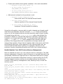
Gambling with Success: Software Risk
Management
by Benjamin A. Lieberman, Ph.D.
Senior Software Architect
Trip Network, Inc.
"Nothing ventured, nothing gained,"
goes the saying. And as many a
visitor to Las Vegas knows, the ideas
of Gain and Risk are highly
intertwined. In software
development, the costs associated
with ill-defined project risks can be
enormous. Without properly
considering these risks, we are doing
little more than throwing the dice
and hoping for a favorable outcome.
A more mature organization realizes
that risk is the price of opportunity,1
and that risks can be well understood
and mitigated. A true "risk" involves
some possibility for loss, and "risk acceptance" is a decision to live with
the resulting consequences for a given risk. It is the primary purpose of
risk analysis to determine which risks have acceptable outcomes -- i.e.,
outcomes one can live with. For example, the loss of $1,000 dollars poses
less risk to a billionaire than to an impoverished family.
One additional component must be present for some occurrence to qualify
as a "risk": the element of choice. If there is no choice about whether to
mitigate or avoid the risk, then the possible occurrence is out of one's
control and better understood as a "chance," or a so-called "Act of God."
The ability to choose which risks are worthwhile (i.e., risks for which the
gain justifies the possibility of loss) and which are foolhardy is core to the
concept of risk management. The concept of choice indicates there is more
than one possible approach available; further, the more choices that are
available, the better the likelihood one of those choices will lead to a
beneficial outcome.
The key to risk management is the identification and mitigation of all true
risks or, failing all else, the development of a contingency plan in case the
potential risk becomes a concrete reality. In this article I will explore the
identification and consideration of risks common to software development,
paying particular attention to the effect of a company's level of maturity
and existing culture on perception of risk.
Management Maturity and Risk
Because all software development involves human beings, the perception
of risk plays a great role in the approach for lessening the probability of
risk occurrence2. Often the "politics and perception" of risk involve ego
and pride on the part of individuals -- some of whom are willing to take on
a greater risk of loss than may be reasonable based on the level of
anticipated gain. Thus, mitigation strategies will differ, based on the level
of "corporate maturity."3 For a young, entrepreneurial company, survival
is based on taking chances, and risk mitigation is mostly about preventing
disastrous losses. For more established firms, what often appears to be
most critical for survival includes maintaining the status quo, so that risk
mitigation centers around eliminating "disruptive" elements or competition
-- i.e., the classic "If it isn't broken, don't fix it" mentality. Finally, for
firms that are highly inflexible to change (what Azides refers to as LateAristocratic or Bureaucratic4), risk management is based on returning to
the status quo, which means eliminating or reducing the need for the
project in the first place.
Thus, a risk that is considered too extreme for an established firm may be
one that a young firm is willing to accept, because it has less to lose and
more to gain. In terms of software development, this may include a
greater acceptance by the executive management of "bleeding-edge"
technologies that have not been firmly established, or a willingness to
experiment with development methodologies or development tools. Often
it is the development group that proposes these approaches, acting on the
mistaken belief that they can meet an unreasonable timeline if only they
apply the "right" process. Risk management in this case should focus on
risk reduction and early elimination of technical risks; these are usually
the least known and most likely to disrupt or derail the project.
In contrast, a well-established firm is primarily interested in maintaining
existing customers and gradually adding new ones, and so will focus more
on risk transfer strategies (such as outsourcing). This is because transfer
approaches allow a company to reduce its overall risk exposure but still
retain control over the risk.
Finally, for the hide-bound, bureaucratic firm, it may be a wonder that a
project is ever started in the first place. Perhaps a new CEO, recognizing
the need for change in order to avoid company failure down the road,
initiates a project. If the company is typically hostile to any sort of change,
then the primary risk management activity is to continually assess the
attitude of executive management. The highest risk is that the change
project will be canceled before there is a chance to show value.
Aside from the company's maturity level, there are many other pitfalls
that can affect risk management in any organization. Consider the traps in
Table 1.
Table 1: Pitfalls for Risk Management
Pitfall
Description
Out of Sight, Out of Mind
Teams often don't pay sufficient attention to risks that
are obvious but not necessarily very visible. They
assume the risk is so obvious that it will be dealt with,
when in fact the risk may be forgotten until it is too
late.
Selective Bias
If the project carries a large number of risks and the
development team has limited skills, the team might
focus on a small subset of the risks rather than deal
with all the risks equally.
Expertise Bias
Some development teams are overly confident; their
attitude is, "We are so good, we can handle any risk,
so why worry?"
Data Presentation Bias
As Mark Twain was fond of saying,5 "There are three
kinds of lies: lies, damned lies, and statistics." He
derided conclusions based on statistical analysis
because it is possible to alter the analysis to fit the
proposition; in other words, you can find support for
any position if you work the numbers hard enough. If a
team uses a statistical approach to analyze risk, then a
rigorous and objective analysis of the underlying
assumptions is required to avoid biasing the perception
of the risk.
Conservatism Bias (dogma)
Comparing current risks to those previously
encountered can be an effective strategy because it
takes prior experience into account; but it can lead to
assumptions that mitigation should be done a certain
way because it has always been done that way.
Law of Small Numbers (variability) This refers to the false assumption that small sampling
numbers have a large associated error (also see Data
Presentation Bias).
Self-Fulfilling Prophesy
The risk is a true one; the team acts in a way that
ensures it will materialize into a problem. For example,
if the team is convinced that the new configuration
management tool will lead to project failure, then they
will not expend the effort to learn the proper way to
apply the tool.
Gambler's Fallacy (probability)
Some people mistakenly think that future probability is
altered by past events -- i.e., the chance that a seven
will be rolled next is smaller because it has been rolled
three times previously. The probability of a risk
becoming an actual problem on a current project is not
lessened because the same didn't materialize on the
previous project.
Incorrect Associations
This refers to assuming a cause-and-effect relationship
between two unrelated situations -- for example,
assuming that a project quality problem is the fault of
the programmers rather than of the poorly conceived
and rapidly changing system requirements.
Sin of Omission
Leaving out critical data is almost as bad as including
incorrect information.
The common theme of all the pitfalls in Table 1 as well as the different
business approaches we discussed earlier is that the people who are
investigating and evaluating risks can alter the perception of risk. The
single most effective strategy for avoiding these pitfalls is to be aware of
their existence, so you can consciously identify and counter them. After
all, success is based on understanding the situation as it truly is, rather
than how we would wish it to be. As the late physicist Richard Feynman
very eloquently pointed out,6 "For a successful technology, reality must
take precedence over public relations, for nature cannot be fooled."
Corporate Culture and Risk
Experts in company behavior have demonstrated that, contrary to what
we might assume, organizational culture is often independent of maturity;
that is, culture is more closely aligned to the style of leadership
encouraged by company executives. According to Geofee and Jones7 there
are four basic cultural types, each with a positive and negative form:
Fragmented, Networked, Mercenary, and Communal.
A Fragmented culture is typified by independent action, such as scientific
research. A well-connected, in-group mentality typifies Networked
cultures, with a focus on personal relationships. Mercenary cultures are
strongly goal-oriented, even at the expense of team morale or well-being.
Finally, Communal cultures are typified by a closely connected group with
well-focused goals (i.e., a "we are family" approach).
As it is for different levels of organizational maturity, the perception of risk
is dramatically different for each culture. A Fragmented culture might view
risk through each individual's eyes, biasing the risk analysis toward
personal gain. Networked cultures are typically more concerned with risks
such as political issues that might affect the health of the team (even over
the health of the company), potentially ignoring other risks to project
success. Mercenary cultures focus on all risks that affect project success,
but are often less concerned with risk to people, such as the risk of
burnout or strained team relationships. Communal cultures, which are
fairly rare, have well-developed interpersonal relationships and are least
likely to bias the risk analysis. However, they are also the most likely to
exhibit arrogance regarding their own success and therefore to assume
risks without enough potential gain to sufficiently counter the potential
loss.
Culture and Maturity Risk Profiles
Within each of the four cultures, it is important, during risk analysis, to
understand the effect that the corporate culture will have on the
interpretation and ranking of risk. The assignment of importance based on
perception should always be considered, or at least reviewed, in this light.
Although corporate culture is relatively independent of corporate maturity,
there are several typical combinations.
The Entrepreneurial Profile. Entrepreneurial companies are often
Mercenary or Communal in nature, and are most influenced by the
company founder. If the founder has a relentless focus on business
success, then the culture will tend to be more Mercenary. If a family
founds the company, then the culture is more likely to be Communal. In
either case, the concern is that risks will be judged to be less
consequential than they really are, given the high degree of arrogance
that is typical of both cultures and fostered by the company style. To avoid
marginalizing critical risks, teams should use objective measures (e.g.,
financial cost, lost business opportunity) to rate risk exposure rather than
a more subjective approach (e.g., past experience, "instinct").
The Mature Profile. Mature companies (five or more years old with
greater than $20 million annual revenue8) are frequently Networked. This
is due to the relatively long period of time that the company employees
have had to work together and form relationships. This combination
provides for stability and good interpersonal relations to judge and
mitigate against risks. The major caveat is to be on the watch for cliques
that seek to protect their own interests (i.e., the well-being of the group)
in opposition to the entire company. One strategy to prevent this form of
"empire building" is to include a senior executive in the project planning
and risk discovery phase of the project, and to encourage cross-team
interactions. The mere presence of a senior executive will discourage
blatant inter-team rivalry, but other team conflicts can be addressed only
by open communication between teams.
The Bureaucratic Profile. Finally, Late Aristocracy/Bureaucratic
organizations have either a strongly Networked or Fragmented culture,
depending on whether the people involved are co-located or distant from
one another. The principal difficulty with this type of organization is its
reluctance to accept the kind of change a new project represents.
Conducting risk discovery and assessment requires obtaining continuous
commitment from senior management and a very aggressive/persistent
project leader who can overcome organizational roadblocks.
Risk Identification and Mitigation
Having considered some of the complex contexts in which risk assessment
will occur, we can turn our attention to the mechanics of risk identification
and ranking. Risks come in many forms, but software companies share a
fairly large set of common risks, as shown in Table 2.9
Table 2: Common Forms of Risk
●
Requirements volatility
●
Poorly defined requirements
●
Unrealistic schedule pressure
●
Low quality (error-prone
modules)
●
●
●
Lack of a defined, repeatable
process
Inadequate organizational
structures
Overemphasis on shortrange planning
●
Cost overruns
●
Corporate politics
●
Excessive paperwork
●
Staff deficiencies
●
False productivity claims
●
Unrealistic budgeting
●
Malpractice (incompetent
management)
●
High maintenance costs
●
Over-engineering
●
Inaccurate cost estimating
●
Subcontractor deficiency
●
●
●
Poor configuration controls
(change management)
Inadequate understanding of
risk
Poor customer relations
(expectation management)
●
●
●
●
Shortfall in the execution of
external tasks
Use of bleeding-edge
technology
Inadequate system
performance
Inadequate deployment
planning
The list in Table 2 is in no way exhaustive, and it is critical to identify,
analyze, and contain any situation that can significantly affect or impede
the project.
Risk Description
There are four basic steps in describing risks, which can help lead to
success in any software development project:
1. Identification: Discovery of potential loss.
2. Assessment: Determining the level of exposure to loss.
3. Mitigation: Creation of a risk containment or avoidance plan.
4. Closure: Successful avoidance or compensation.
These steps will lead to a complete description of all risks, which should be
captured in a formal "Risk List."10. Each risk on the list should have the
following details:
●
Definition: Concise statement of the risk.
●
Consequence: Expected impact if the risk is realized.
●
Likelihood: Probability that the risk will occur.
●
Exposure: Expected loss weighted by the probability of occurrence
(Exposure = Likelihood * Consequences).
●
Risk Ranking: Relative ranking-based consideration of Exposure.
●
Indicators: Signs and symptoms to monitor the risk.
●
●
Mitigation Strategy: Description of approach to avoid realization of
the risk.
Contingency Plan: Secondary plans to deal with consequences of
risk realization.
Now that we have a framework for capturing risks, we can identify and
assess each risk in turn.
1. Identification of Risk
The first step in any risk management scheme is to identify all the factors
that can lead to delay or cancellation of the project. Many of the risks in
Table 2 are associated with the development process, the product under
construction, or the management of the project itself. The project team
should therefore consider these three areas while asking the following
questions to determine the types of risk, the likelihood of occurrence, and
the impact the risk would have on the project:
●
What can go wrong?
●
How likely is this to occur?
●
What would be the cost or damage if this happened?
●
How can we avoid this?
2. Assessment of Risk
The second step is to assess the level of exposure for each risk. If the
actual dollar values can be determined, it is of benefit to provide this
information as part of the risk description. This permits a non-biased
ordering and ranking of the risk impact. Alternatively, you can use a
simple scale to qualitatively rank the risks,11 as shown in Figure 1:
Figure 1: Qualitative Ranking Scale for Risks
A low-impact risk is one that incurs only negligible costs. Alternatively, a
devastating impact risk is one that will lead to project cancellation, legal
issues, and/or termination of the project team. When determining risk
impact, it is helpful to take a backward-looking approach -- that is, to
pretend as if the risk has already materialized and judge the resulting
situation. As you do this, you should consider the effects on project
personnel, customer satisfaction, and senior executive confidence, as well
as the actual economic costs borne by the business.
Likelihood is a simple probability assessment from 1% (very unlikely) to
99% (all but unavoidable). Indicators are signs and symptoms that
suggest the risk has either been mitigated or is occurring; for example, if
the risk is customer satisfaction, then a poor customer response to a
release is an indicator that the risk is occurring or has already occurred.
Mitigation of Risk
Risk mitigation is an attempt to avoid or prevent the consequences
associated with the risk. There are three primary mechanisms for
mitigation:
1. Risk reduction: Reduce the probability of risk occurrence by
forward planning.
2. Risk avoidance: Reorganize the project so that it cannot be
affected by that risk.
3. Risk transfer: Reorganize the project so that someone or
something else bears the risk (customer, outsource vendor, another
company, another department, or the like).
Mitigation plans should be written and placed into effect as soon as
possible. Since a key element of iterative software development is to take
a risk-based approach to development and attempt the highest risk items
early in the project, teams should address and retire the highest impact
risks as early as possible in the development lifecycle. Addressing highrisk items early in the project is beneficial for several reasons:
●
●
●
It leaves you plenty of time to deal with risk-generated problems.
It reduces the impact of potential risks on the quality and timeliness
of system delivery.
The costs associated with a risk often increase over time.12
Contingency Plans contain steps that should be taken once a risk becomes
a reality. For example, if the risk is to project schedule, than the
contingency will be to maintain a time "buffer" to be used if the mitigation
strategy of iterative development fails. For technological risks, the
contingency may be to have a fallback plan to continue using the current
solution while the new solution is made to work. Finally, for political risks,
the contingency may be to petition the most senior executive in the
company if a lower level executive becomes an impediment (typical of
Bureaucratic firms).
As noted earlier, options must be associated with any endeavor that has
enough potential for loss to qualify as a risk. In the event that a risk is
realized, it is best to have a plan in place to deal with the costs and
minimize impact to the project. Just as with a city disaster plan, the hope
is that this plan will never have to be used, but it is best to define and
practice it beforehand, just in case. A contingency plan might include
additional schedule time "held in reserve," additional budget for
emergency consultants, or other pre-disaster planning.
Conclusion
Risk management is critical for a project's success. An understanding of 1)
how personal biases affect risk perception, and 2) the effect of corporate
culture and maturity on risk planning and acceptance can better prepare
the project team to manage major project risks. These influences must be
carefully and objectively considered when creating a risk management
plan. Risk management starts with the identification and documentation of
situations or conditions that can lead to undesired consequences, including
project cancellation. Risk mitigation consists of reducing the threat,
avoiding undesired consequences, and/or transferring costs for identified
project risks.
By assuming a risk-based approach to scheduling, including addressing
the highest-risk items early in a project, the project team can increase the
overall probability of success. It is important to avoid gambling with a
project's success, which means accepting risks that are not justified by
potential gains. By adopting a more rational approach to risk, the project
development team will be able to prepare for all foreseeable circumstances
and plan to meet them. Running successful projects, therefore, involves
spending time to determine potential threats, understanding relative costs
and benefits associated with those threats, devising mitigation plans to
avoid realization of associated costs, and creating contingency plans to
deal with possible undesirable outcomes.
References
E. Hall, Managing Risk: Methods for Software Systems Development.
Addison-Wesley, 1998.
R.N. Charette, Applications Strategies for Risk Analysis. McGraw-Hill,
1990.
I.Azides, Corporate Lifecycles: How and Why a Corporation Grows and
Dies and What to Do About It. Prentice-Hall, 1988.
Mark Twain (Charles Neider, Editor), Mark Twain's Autobiography. Harper
Perennial, 2000.
R.P. Feynmen, What Do You Care What Other People Think? Bantam
Books, 1988.
R.Goffee and G. Jones, The Character of a Corporation. Harper Collins,
1998.
E. Flamholtz, Growing Pains - How to Make the Transition from an
Entrepreneurship to a Professionally Managed Firm. Jossey-Bass
Publications, 1990, p.407.
B.W. Boehm, Software Risk Management. IEEE Press, 1989.
C. Jones, Assessment and Control of Software Risk. Prentice-Hall, 1994.
I. Jacobson, G. Booch, and J. Rumbaugh, The Unified Software
Development Process. Addison-Wesley, 1999.
W. Royce, Software Project Management. Addison-Wesley, 1998.
Notes
1
E. Hall, Managing Risk: Methods for Software Systems Development. Addison-Wesley,
1998.
2
R.N. Charette, Applications Strategies for Risk Analysis. McGraw-Hill, 1990.
3
In this context, "maturity" relates to the natural growth of a company, and refers to the
corporate business approach (e.g., entrepreneurial, balanced, change adverse, etc.). This
should not be confused with the SEI's Capability Maturity Model (CMM), which measures the
level of competence with respect to the software development process.
4
I.Azides, Corporate Lifecycles: How and Why a Corporation Grows and Dies and What to Do
About It. Prentice-Hall, 1988.
5
Mark Twain (Charles Neider, Editor), Mark Twain's Autobiography. Harper Perennial, 2000.
6
R.P. Feynmen, What Do You Care What Other People Think? Bantam Books, 1988.
7
R.Goffee, and G. Jones, The Character of a Corporation. HarperCollins, 1998.
8
E. Flamholtz, Growing Pains: How to Make the Transition from an Entrepreneurship to a
Professionally Managed Firm. Jossey-Bass Publications, 1990, p.407.
9
See B.W. Boehm, Software Risk Management. IEEE Press, 1989, and C. Jones, Assessment
and Control of Software Risk. Prentice-Hall, 1994.
10
I. Jacobson, G. Booch, and J. Rumbaugh, The Unified Software Development Process.
Addision-Wesley, 1999.
11
E. Hall, Op.Cit.
12
See Jacobson, Booch, and Rumbaugh, Op.Cit., and W. Royce, Software Project
Management. Addison-Wesley, 1998.
For more information on the products or services discussed in this
article, please click here and follow the instructions provided.
Thank you!
Copyright Rational Software 2002 | Privacy/Legal Information
Copyright Rational Software 2002
http://www.therationaledge.com/content/jul_02/m_requirementsManagement_cc.jsp
Requirements Management Practices for
Developers
by Catherine Connor
Leonard Callejo
Rational Software
As a developer, do you get
requests from every corner to
incorporate "minor" changes into
your code that will supposedly
improve the existing system? Are
you often working from incomplete
or inaccurate specifications that
leave you wondering what the
requirements are actually trying to
convey? Do you sense that the
requirements are not truly known,
and that you are therefore aiming at a constantly moving target? Do you
feel as if you're at the tail end of a whip, constantly reacting to the lashes
of fickle customers?
If you answered "yes" to any of the above questions, then keep reading:
There is hope. Although many software development organizations still
assign RM responsibility exclusively to the analysts on a project team,
many others have realized that when developers contribute to RM
practices, the project team has a much greater chance of successfully
delivering the right solution to the customer. The goal of this article is to
illustrate what this critical role entails and to provide RM implementation
tips that developers can apply to help their teams succeed.
Why Should Developers Care About Requirements
Management?
To understand how important it is for developers to get involved in RM,
reflect for a moment on the purpose of RM: to establish a common
understanding between the customer and the software team. That
common understanding is the basis for planning and managing the
project. Without effective RM, a team has limited ability to construct an
accurate project plan, control project scope, deliver on key milestones, or
prevent development and testing resources from being wasted on the
wrong tasks.
Developers can play a crucial role in ensuring that the team is working
from a complete set of clearly expressed requirements. Developers should
get involved early on with the requirements specification and continue to
help clarify and refine requirements as these evolve through the iterative
development lifecycle. Developers are responsible for turning concepts
into reality, so the sooner they take an active role in the requirements
process, the greater the likelihood that the requirements can be accurately
translated into a workable system -- within the shortest amount of time.
Studies such as the Standish Group reports (see References below) have
shown that requirements errors are the most expensive and aggravating
errors to fix -- and the longer they go uncorrected, the more costly they
become. Starting with a requirement that takes you in the wrong
direction, or changing direction in the middle of the development lifecycle,
can invalidate your design and result in expensive architectural rework,
inaccurate validation tests and user documentation, and so on. You'll
spend more and more time fixing problems that you might easily have
avoided in the first place.
Proper RM can also simplify a developer's life. When Quality assurance
(QA), quality engineering (QE), and documentation teams work from
quality requirements that are clear, then they don't have to interrupt
developers with questions about what to test. In addition, those in charge
of maintenance can focus on actual implementation defects in the system
rather than problems stemming from fuzzy requirements. Better
requirements management ultimately leads to better quality software, and
that enables developers to focus on forward-thinking enhancements.
How Formal Does RM Have to Be?
In general, the more informal your RM process, the greater the risk that
your solution will not satisfy the customer. Common arguments for
adopting a loose RM process include:
●
It will allow us to develop faster.
●
It will give us more flexibility to adapt to changing market demands.
●
We don't need formal requirements documents to know what we
are supposed to create.
Unfortunately, these are precisely the arguments that come back to haunt
many project teams. Before adopting a position, the team needs to
analyze carefully the degree of RM formalism required for project success.
Fundamentally, your RM practices should yield:
●
●
●
Requirements that are clearly understood by all team members.
Control over changing requirements to keep the team on track for
delivering the right solution.
Effective communication to keep the entire project team on the
same page.
Of course, in certain cases, adhering to a very formal RM practice might be
overkill. For instance, if your team is tasked with building a video game,
then you can expect enhancement and change requests to pour in at a
rapid rate. Following a traditional change control process that includes
obtaining approvals from a Change Control Board (CCB) might inhibit
developers' creativity, act as a bottleneck to software delivery, and
ultimately compromise the project's chances for success. Even in this
instance, however, the team would benefit from using selective RM
techniques, such as storyboards or prototypes, to validate game ideas
before committing to develop and deliver them.
At the other extreme are cases that demand strict adherence to formal RM
practices. For example, if your project team is tasked with developing
software to run a medical device that automatically administers an exact
amount of medication to a human patient under certain variable
conditions, then your team should adopt a highly structured RM process to
ensure total accuracy. Making a mistake with a requirement in this
situation could lead to loss of human lives.
Solutions for Requirements Management Problems
that Affect Developers
Let's get down to specifics. In this section, we will look at some
requirements-related problems that affect developers and propose RM
approaches to remedy them.
Problem 1: Incomplete Requirements Specifications
Among the top RM challenges your team faces are the inevitable
ambiguities in the first version of a requirements document. When was the
last time you read a first-version RM document and felt confident that you
had a solid understanding of what you were expected to build? The first
version of requirements documents are almost always incomplete and
ambiguous to some extent. Unfortunately, most requirements documents
do not undergo revisions beyond the first draft; this means they lack
sufficient information for developers to design their part of the system,
leaving them to "interpret" what users want.
Despite analysts' best efforts to gather and document requirements
through RM workshops, joint application development (JAD) sessions,
interviews, or focus groups, developers often have many questions after
their initial review of the requirements. This is true no matter how much
subject matter expertise the analysts have. Often, developers simply
provide a different perspective that the analyst might have overlooked.
For example, they might raise exception situations that users may
encounter but which the analyst failed to anticipate. Therefore, it is
imperative that developers and analysts work closely together to refine
the original requirements specifications before starting design.
Remedy: Detailed and Unambiguous Requirements
Specifications
Good RM practices recognize that requirements specification reviews
should be the norm rather than the exception on any project. The entire
project team should review the first version of the specification, and
developers should have sufficient time to raise questions. In turn, the
requirements analyst should have sufficient time to answer these
questions and document clarifications. In particular, the analyst needs
time to investigate questions directly with the customer to gather more
details. It is essential that all developer issues be addressed before design
begins. Otherwise, the developers might make their own assumptions and
introduce unwanted elements into the system.
In addition to reviews, teams can employ use cases to express functional
requirements. Use cases describe how a system behaves when interacting
with the outside world by documenting system functionality as a dialog
bewteen the user and the system. This provides software teams and their
customers with a common understanding of the system's expected
behavior, from a user's perspective. It is critical that developers play an
active role in detailing these use cases in order to improve the clarity of
requirements and thereby minimize misunderstandings. Analysts often
gloss over major use cases (usage scenarios) and conclude that there are
no major issues. However, once the developer begins to flesh out the
details by identifying alternative use-case flows (usage scenarios based on
something going wrong), then the real issues begin to surface. If a
developer does not do this elaboration work before design, then the design
will need to be reworked many times to incorporate all user scenarios.
Consequently, the ability of the developer and analyst to establish a
strong, collaborative relationship at this stage often determines the
success of the final product.
Note, however, that not all requirements can be expressed in use cases.
For instance, reliability and performance requirements are better
expressed in declarative form (e.g., "The system shall..."), but use cases
do provide a mechanism to document the user experience with the system
in a comprehensive way. By focusing on the user point of view, use cases
also eliminate unwanted design elements in requirements specifications
and thereby free designers from unwarranted design constraints.
Problem 2: Constant Change Requests
The Standish Group's 2001 Extreme Chaos report states that "Changing
requirements are as certain as death and taxes." Gaining control over
these changing requirements is critical to the success of a project, and it is
a practice that directly impacts the lives of developers. Consider your own
projects. How often do sales or marketing people ask you to incorporate a
customer-requested change into your code? Do you graciously try to
accommodate these requests by working extra hours? If so, then you are
doing your team a disservice. These constant interruptions have a
negative impact on your productivity; they make it harder to concentrate
and stay focused. But even more important, they can be devastating to
the project plan and overall software quality. Even the smallest change
can have a ripple effect on other team members and project areas. For
example, unless the testers are informed about the change, they won't
build the necessary validation scripts to test it, and the resulting impact on
QA/QE or documentation might delay the entire project schedule. In
general, these constant interruptions can cause project plans to expand
("scope creep"), sidetrack the team from its initial objective, and result in
software that does not meet the customer's expectations.
Remedy: Control Requirements by Assessing Potential
Impact
The remedy is a set of RM practices that prevent developers from making
casual changes before the team evaluates their possible impact.
Requirement specifications should change only after they pass the criteria
set by a Change Control Board (CCB) representing, at a minimum, the
customer, the development team, and the testing team. This Board's
responsibility is to evaluate every change request from three points of
view: customer, development, and testing and documentation.
(Depending on the type of application, training and support staff might
need to be involved as well.)
●
●
●
●
The development representative should assess all design areas that
the change request impacts, as well as the level of effort required to
implement the change. He or she might call on developers for help
in analyzing the proposed change's potential impact.
The QA representative should assess the feasibility and level of
testing effort associated with the proposed change. A change that
might be easy to incorporate in code might be very difficult, or even
impossible, to test.
The customer representative provides the business perspective and
ensures that the change does not distract the project from pursuing
its original business objectives. This person should also provide
additional information about the change to help the CCB understand
customer needs.
It is wise to include representatives from training, support, and
documentation on the CCB, because change requests often impact
these areas as well.
Each Board member should be responsible for finding an adequate
replacement in case of absence so that the assessments of change
requests are unbiased. If all parties are not represented, then the Board
should defer the evaluation process.
Using an iterative approach to development rather than a traditional
waterfall approach is also a great help in managing changes to
requirements. Traditional approaches freeze requirements specifications at
the start of a project and theoretically don't allow changes until after the
software is released. That approach encourages people to go directly to
developers and ask them to change their code, which brings on all the
negative consequences we discussed above. Iterative development, in
contrast, allows software teams to split the work into iterations with
internally stable requirements. At the start of the next iteration, the team
gets a chance to update the requirements specification and incorporate
any changes that were submitted and accepted during the previous
iteration. As specifications can change only at the start of an iteration,
developers can concentrate on a firm set of requirements during the
iteration itself.
Problem 3: Being in the Dark about Changes that Affect Your
Work
As a developer, when requirements change, how are you informed? Often
developers work on obsolete requirements because someone forgot to
inform them of a change that impacts their work. Although the analyst on
your team might discuss alternatives with a particular developer to gauge
the impact of a change before voting to accept it, he or she may fail to
realize the impact it might have on the work of other developers on the
team. Also, even when you hear about a change in requirements, unless
someone on your team is tracking the relationships between requirements
and the design elements created to fulfill them, it is very hard to quickly
and accurately assess the impact the change will have on your work.
Remedy: Requirement Change Notification
If your team assigns someone to track dependencies between
requirements and design artifacts, then as soon as a requirement changes,
that person can pinpoint which part of the design will be affected and
inform all the developers working on it. Also, developers will know they
can contact that designated person to make sure they are up to date on
the latest requirements.
Because requirements are moving targets, this tracking person will need
to use traceability -- the ability to track dependencies between
requirements to ensure that requirements are actually implemented.
There are various levels of traceability, but basically its purpose is to
provide some assurance that the functionality you committed to your
customers will indeed be implemented (coded by developers) and will
work as specified (validated by testers). Tracing requirements to design
elements is key to ensuring that those requirements will be implemented
and helps in assessing the impact of a requirement change on design. To
ensure that requirements are validated and that test validation is updated
when a requirement changes, requirements should also be traced to test
artifacts, typically test cases.
What about tracing requirements to source code? Although this idea
seems appealing at first (e.g., if I change a requirement, then I will know
which piece of code must be updated), it is actually impractical, because
code is more dynamic than are requirements. If you start with a design
and then optimize it, then the new design will likely result in code changes
but still comply with requirements. Maintaining traceability links takes
time, which is something software teams never have enough of, so you
should use traceability judiciously. Skip using it for coding changes unless
you work on systems that are audited by standards bodies, like the FDA,
which mandate traceability from requirements to code, sometimes even
lines of code. Even in such cases though, do not trace requirements to
code while building the software. You only need to report that the final
product requirements trace to code and that no piece of code was built
without fulfilling a requirement. If you try to get more detailed than that,
then managing traceability links between requirements and source code
will become a full-time job -- with few rewards.
Problem 4: Obsolete Requirements Specifications
The requirements specification document is the primary means an analyst
uses to ensure that everyone on the team understands what system needs
to be developed and what customer problems the system should address.
It is critical that developers can easily locate this document, and that it be
kept up to date. These seem like obvious, simple instructions, but the
process can be complicated. Specifications often are reviewed on an ad
hoc basis; so when decisions are made and assumptions are drawn, the
requirements do not always get updated in a timely manner. Furthermore,
when they are finally updated, the requirements do not always get
redistributed to the team, or they might get lost amidst the clutter of email in everyone's inbox.
Remedy: Up-to-Date Specifications Readily Available
Good RM practice dictates that the team clearly designate a central
repository for the requirements specification document so that everyone
always has access to the latest version. This ensures that developers will
not waste time and effort coding against obsolete requirements. As an
extra step, it is also a good idea to notify the team (via e-mail, phone,
meeting, etc.) when the requirements specification document has been
updated.
Six Tips for Improving
Requirements
Management in your
Organization
In addition to the remedies we
suggest above, here are a few
simple and effective guidelines
developers can use to help prevent
the four problems we just discussed
from occurring in the first place.
A Requirements
Management Tool for
Developers
Rational RequisitePro, one of the most
powerful requirements management
solutions on the market, provides many
benefits to developers3:
●
●
Tip 1: Participate in
Establishing a Change
Request Process
●
This may seem daunting, but it is
actually quite easy to achieve.
Simply put, any requests for change
should be validated before they are
accepted.
●
●
The first step in establishing a
●
●
●
Fast access to the most current
requirements specifications.
Control over requirements changes.
Quick access to the Glossary when
reviewing specifications.
Complete audit trails of
requirement creation and changes.
Immediate identification of how
requirements changes will impact
design.
Use-case specification templates.
Ease of use through tight
integration with Microsoft Word, the
most widely used format for
requirements specifications (see
change request process is to
determine how your team will
collect and manage change
requests. The simplest method
is to create a standard form
that everyone can fill out and
submit either via e-mail or fax,
or in person. A more robust
method would be to employ a
tool like Rational®
ClearQuest.®
●
●
Next, determine how you will
store these requests. Will you
keep the paperwork in a threering binder or an electronic
database? Using a commercial
defect and change tracking
tool (like Rational ClearQuest)
greatly simplifies the
management of change
requests by allowing people to
submit them over the Web;
this requires no local software
installation and allows the CCB
to review the change requests
and determine which ones to
accept.
Figure 1).
Click to enlarge
Figure 1: Rational RequisitePro
Features Tight integration with
Microsoft Word
Rational RequisitePro is also integrated with
Rational's Rational XDETM4 development
environment, as well as with Rational
Rose.®5 With these integrations, you get
seamless navigation from use-case
diagrams -- documented in either Rational
XDE or Rational Rose -- to the use-case
specifications stored in Rational
RequisitePro. RequisitePro maintains usecase specifications as true requirements
documents, so you get all the benefits of
managed requirements while documenting
software use cases.6
Finally, decide how often the CCB should meet to review change
requests and determine criteria for deciding which ones to
implement.
Tip 2: Enforce the Change Request Process by Just Saying
NO
As a developer, you can play a critical role in making the change request
process work for your team. If you continue to accept and implement ad
hoc change requests from salespeople, customers, senior management,
and others without having the CCB assess them, then you and your team
will continue to feel plagued by constant demands for change. Also, your
behavior will only increase the number of ad hoc requests that come
directly to you, because the requestors will know you are a "soft touch."
Instead, you must learn to say "no" to your requestors and direct them
toward your established change control process. This can lead to high
pressure from salespeople, for example, who are often the instigators of
ad hoc requests that are accompanied by claims such as, "I can close the
XYZ account if you add that feature," or "I have been losing deals lately to
the competition because we don't have the ABC feature." No matter what
arguments people use, you and your development team have to exhibit
strong discipline and politely direct these people to the proper change
request process. Although they may not change their behavior overnight,
if they understand the benefits of the process and that you are firm and
dedicated to this process, then they will change their behavior over time.
Tip 3: Establish and Participate in Requirements
Specification Reviews
As a developer, you know that whenever you receive a set of requirements
you likely will have many questions, because some of the specifications
are unclear or ambiguous. Make sure your team's project plan allocates
time for periodic requirements specification reviews. The benefits of this
are many: You do not have to make guesses about the changing spec;
you better ensure that your team will deliver what the customer is asking
for; and you avoid rework for yourself and for your team. These reviews
do not need to be terribly formal; they should be an open forum in which
the development team can discuss pieces of the requirements specification
to ensure that everyone has the same solid understanding of the
requirements.
You should be an active participant in these review sessions and come
prepared with preliminary designs or concepts based on your
interpretation of the requirements. This process is highly iterative in
nature; typically, you need multiple sessions to establish a solid
understanding of the requirements and prepare to move into design.
Through these iterations, the analyst on your project team can ensure that
all changes are properly captured and documented. Furthermore, these
iterative reviews provide a self-checking mechanism for the team to
ensure the quality of both the software requirements and preliminary
designs. By keeping both of these artifacts in synch, the project team can
move forward together and increase its chances of delivering a successful
solution. Consequently, time should be allocated to continue the reviews
through the design phase; that is when many developers discover more
ambiguities in the requirements specifications that must be resolved so
that they can proceed with their work without making assumptions they
will later have to correct.
Tip 4: Maintain a Glossary
A glossary document that is owned, developed, and maintained by the
analyst is a simple yet powerful way to remove ambiguity from
requirements specifications and avoid misunderstandings. The glossary
does not need to list every term used in the requirement specifications,
but it should definitely include any that might be subject to multiple
interpretations. If terms defined in the glossary have specific and
important relationships to other terms (e.g., in building a financial
application, a customer can only have a set number of accounts, and no
more than two customers can share the same account), then you may
want to supplement the glossary with a domain model that visually depicts
those relationships (e.g., between customer and account), as the software
will need to respect them.
Any member of the project team can suggest terms for the analyst to add
to the glossary, but the entire team must agree upon the terms'
definitions. As a developer, you must take responsibility for understanding
the key terms related to the system area for which you are responsible.
Tip 5: Insist on a Project Vision to Guide Your Solution
To help developers understand the application of the software you will be
building, your project leader or analyst should be documenting the specific
business problems your team will be tasked to solve with this project.
Without an understanding of these problems, developers run a great risk
of creating something that will not be useful to customers.
Think about a competitive athlete, a runner, for a moment. Before the
season begins, the runner establishes a primary goal to accomplish. Then
he analyzes his strengths and weaknesses and develops a training plan
with periodic minor goals that will allow him to accomplish his primary
goal. As he trains, unexpected things are bound to happen -- such as
injuries, illness, and bad weather -- that force him to alter his training
program. However, by keeping his goal in focus, the runner is able to
adapt to the changes and adjust his training so that he is still able to
achieve his primary goal. Without keeping such a focus on his primary
goal and maintaining discipline in striving for his minor goals, the runner
would be highly susceptible to making incorrect adjustments to his training
program that would prevent him from ever achieving his primary goal.
Similarly, on software projects, teams need to have a clear understanding
of the project vision and a corresponding project plan with intermediate
milestones to help them achieve their primary goal. Inevitably, during a
project certain factors come into play (e.g., technical limitations,
unforeseen performance problems, etc.) that alter the original course of
action. Also, it is common for team members to lose sight of the vision in
the middle of a project and become very myopic in their work. These
things can cause teams to stray from their intended path and prevent
them from fully achieving their original goal. Just as the runner has to
adapt to changes and stay disciplined by striving for minor goals while
maintaining focus on his primary goal, so too must a project team be
adaptive yet disciplined. The team must strive for its milestones, always
focusing on its overall vision. Therefore, as a developer, before you dig
into the requirements and start designing, review your project's Vision
document. If one does not exist, then insist that your project leader or
analyst develop one before you get started. You might avoid wasting a lot
of time building useless software.
Tip 6: Adopt Use Cases to Illustrate System Functionality
Express functional requirements in the form of use cases to better
understand how people will actually use the software. As you create usage
"stories" for the software, you will flush out requirements details and save
yourself from having to do a lot of guesswork. Use cases are unique in
their ability to express requirements and describe what the software
should do for users in a format accessible to both technical and nontechnical folks. By enabling software teams to avoid traditional user and
system representations of requirements that often lead to a disconnect
between less technical analysts and developers, use cases provide a better
chance that everyone will understand and agree on the expected system
functionality.
In addition, with use cases you can create use-case storyboards, a great
alternative method for building a user interface prototype to validate
usability requirements. Use-case storyboards are logical, high-level
descriptions of how the user interface will present to users the
functionality described in the use case. As they are much faster to develop
than the actual user interface, you can employ use-case storyboards to try
out various user interface options before you prototype, design, and
implement an actual interface.
Writing good use cases takes practice, and Rational provides resources to
help, including Webinars and articles on The Rational Edge1 and the
Rational Developer Network.
Automating the Requirements Management
Process
An automated tool can support all the requirements management
practices we've discussed, but it's important to remember that an RM tool
is only as good as the process it automates. Furthermore, the tool can
automate only parts of the process; no tool can replace good
communication among team members. To be successful, first be sure that
your organization's RM practices are sound and work well. Then introduce
an RM tool, and your team will be able to benefit from using it.2
In addition to an RM tool, consider automated process support. Although
you can find plenty of guidelines for best practices in books (see
References below), providing your team with just-in-time access to
guidelines is one way to help ensure that people will follow them. That is
why Rational publishes the Rational Unified Process as a navigable and
searchable Web site.2 The RUP defines best practices for RM, including
team roles and responsibilities (see Figure 2).
Figure 2: RM Best Practices in the Rational Unified Process
The RUP also includes tool mentors, which spell out exactly how to
implement RM best practices while using Rational RequisitePro (see Figure
3).
Figure 3: Rational RequisitePro Tool Mentors Provide Tool Guidance Inside the
Rational Unified Process
The Key: Require Good Requirements
As we've discussed, effectively managing a project's evolving
requirements can have a huge impact throughout the development
lifecycle. Requirements define what to design, what to test, and what to
put in the user manual -- and requirements errors are the most costly to
fix. Yet once you know what to watch for, such errors are relatively easy
to avoid. And developers can play a key role in helping the team avoid
them.
Given today's pressures to deliver software, it's critical that developers
take an active role in formulating unambiguous and complete
requirements right from the start, before they begin design -- because
they may not have time to fix defects caused by poor ones. Then, by
refusing to incorporate changes that are not approved, developers can
reduce daily rework and frustration and help their team deliver software
that actually solves customers' problems. By taking an active role in
requirements management, you, as a developer, can both minimize the
chaos in your life and help your software projects succeed.
References
These sources can help you and your team understand the value of
adopting good RM practices.
●
●
●
●
●
●
Rational Software, "Achieving ROI with Rational Requirements
Management Tools" (IDC-sponsored study). Available at
http://www.rational.com/products/whitepapers/431.jsp
Rational Software, "Understanding and Implementing Stakeholder
Requests: The Integration of Rational ClearQuest and Rational
RequisitePro." Available at
http://www.rational.com/products/whitepapers/414.jsp.
Standish Group, "Extreme Chaos Report 2001." Available at
http://www.standishgroup.com/
Dean Leffingwell and Don Widrig, Managing Software Requirements:
A Unified Approach. Addison-Wesley, 1999.
Rational Software, Virtual demos of Rational RequisitePro. Available
at http://www.rational.com/tryit/reqpro/seeit.jsp.
Rational Developer Network, http://www.rational.net. Provides a
wealth of information for software developers at Rational customer
companies (registration required), including guidance on
requirements management and Java and .NET development
processes.
Notes
1
See articles by Leslee Probasco, Ellen Gottesdiener, Anthony Crain.
2
Rational provides a complete RM solution, including process guidance in the Rational
Unified Process (RUP), tool automation with Rational RequisitePro, and public or on-site
classes from Rational University (http://www.rational.com/university/index.jsp). Rational also
offers various forms of onsite Professional Services through local customer teams.
Get a glimpse of the RUP at http://www.rational.com/products/rup/index.jsp
3
View demos of Rational RequisitePro online at:
●
http://www.rational.com/products/reqpro/index.jsp (overview)
●
http://www.rational.com/tryit/reqpro/seeit.jsp (detailed demos)
4
See www.rational.com/xde
5
See www.rational.com/rose
6
For more information on these integrations, see the use-case management white papers on
the Rational Web site (www.rational.com/products/reqpro/whitepapers.jsp).
For more information on the products or services discussed in this
article, please click here and follow the instructions provided.
Thank you!
Copyright Rational Software 2002 | Privacy/Legal Information
Copyright Rational Software 2002
http://www.therationaledge.com/content/jul_02/r_primalLeadership_sf.jsp
Book Review
Primal Leadership: Realizing the Power of Emotional Intelligence
by Daniel Goleman, Richard E. Boyatzis, Annie McKee
Harvard Business School Press, 2002
ISBN: 1-57851-486-X
Cover Price: US$26.95
352 Pages
When I began reading this latest effort by Daniel Goleman et al., I was a
bit skeptical. Seems like an increasing number of what I call "Kumbaya"
books have come onto the market lately -- books promoting the touchy,
feely side of leadership. Fortunately, I was pleasantly surprised: This work
offers much more than that. I found myself relating to many of the real
world situations that are used as context for Goleman's claims. This realitybased context made the information much more meaningful and allowed
me to see the practical side as well as the theoretical.
The basic claim Goleman makes in Primal Leadership is that a leader's
behaviors are just as important, or even more so, than other attributes
leaders must possess, such as vision, intelligence, and so on.
In the first part of this book, Goleman and his co-authors help us assess
who we are as leaders, what styles we use, and how people perceive us.
They identify four behavioral domains important for leadership:
●
●
●
●
Self Awareness. This includes the ability to read our own emotions
and recognize their impact on others, know our own limits and
strengths, and have a good sense of our capabilities.
Self Management. This domain encompasses having emotional
self control, being honest, adaptable, and driven to improve
performance and meet standards of excellence, and possessing
initiative and optimism.
Social Awareness. Leadership requires empathy and sensitivity to
others' emotions, taking interest in others, organizational and
political awareness, and a willingness to serve the needs of both
customers and employees.
Relationship Management. Success in this domain rests on our
ability to guide and motivate others, to influence people and help
them develop, and to serve as a catalyst for change, manage
conflict, and forge the bonds required for effective teamwork and
collaboration.
The authors claim that very few people are excellent in all four domains
(How many can you think of?), but successful leaders are very competent
in at least two or three.
The authors also theorize that different situations require different types of
leadership. This seems like common sense, but in my experience, the
dynamic range of most managers is rather limited. Therefore, I thought
the chapters that discuss various leadership styles (Visionary, Coaching,
Affiliative, Democratic, Pacesetting, Commanding) were quite accurate.
The examples are good, too; The authors present the pros and cons of
each style within the context of an actual business situation, explaining
that the style should map to the situation. You wouldn't want a democratic
leader in a battle situation (commanding style would be preferable here),
for example, and you wouldn't want a pacesetting style in an academic
environment (affiliative or coaching styles would be top choices in this
situation).
Emotional Intelligence versus Strategic Thinking
Another important point the authors make in this book is that it is critical
to put people before strategy. Here I thought they were a little off.
Although I agree that you should never discount the importance of people,
I believe that you should consider them in parallel with strategy. Why?
Because I strongly feel that leaders need a balance between emotional
intelligence (the personal, behavioral side of leadership) and what I call
functional intelligence (the vision, knowing the market, decision making,
judgment, etc.) in order to do their job effectively. If we spent all our time
building teams and rallying the troops but ignoring business strategy, then
how would we know in which direction we were going? And what type of
people we needed to get there?
In fact, as I read farther into the book, I got the feeling that the
perspective was getting progressively more academic and psychological
and less pragmatic. I would also like to have seen more data to support
several claims the authors make. For example, when they say that a new
manager in a failing company turned the organization around and became
successful (there are many examples like this in the book), it would have
been helpful if they had elaborated on a few specific key actions that
contributed to the person's success. Instead, the reader must be content
with referring back to their theories about success and drawing whatever
conclusions one can from the scanty description of the situation.
These frustrations notwithstanding, I highly recommend this book to
everyone in any management role, especially in the technical field. All too
often, we discount the importance of applying emotional intelligence in our
interactions, which can certainly affect a team's willingness to get behind a
leader. Like Goleman, I've always believed that without the motivation and
commitment of the entire team, successes are short-lived and rarely
sweet. But I also believe that, to succeed, leaders need more than the
traits discussed in this book; they must also know and be able to apply the
business fundamentals and practical mechanics required to thrive in a real
work environment.
-Sid Fuchs
Director of Professional Services
Rational Software
For more information on the products or services discussed in this
article, please click here and follow the instructions provided.
Thank you!
Copyright Rational Software 2002 | Privacy/Legal Information
Copyright Rational Software 2002
http://www.therationaledge.com/content/jul_02/r_leadingQuietly_jl.jsp
Book Review
Leading Quietly: An Unorthodox Guide to Doing the Right Thing
by Joseph L. Badaracco, Jr.
Harvard Business School Press, 2002
ISBN: 1-57851-487-8
Cover Price: US$25.95
224 Pages
Ever since King Solomon offered to bisect that baby, it's been clear that
effective executive decision-making requires the incumbent to possess
both wisdom and moral authority. However, even with the current
recession firmly in place, there simply aren't that many ex-monarchs of a
similar caliber out there job-hunting just now. (And even if there were,
then what with the price of thrones, red carpeting, and palace flunkies
these days, they would be hard to sell as potential CEO candidates to any
half-decent board of directors.) Nonetheless, Silicon Valley has done an
excellent job of generating its own royal pretenders: Steve Jobs, Larry
Ellison, and Scott McNealy, to name but three. Like modern-day royalty,
these are personalities that get to live life in the full glare of the media
spotlight. And over time, they've come to personify what a CEO surely has
to be, right?
Wrong. The reality is -- and must be -- that the vast majority of
businesses operate perfectly well, thank-you-very-much, without
superstars. As the author of this new book puts it, "Quiet leadership is
what moves and changes the world."
A perfectly reasonable premise, but, as it turns out, only one aspect of
what this book sets out to achieve. Leading Quietly is just as concerned
with the moral dimension of leadership as it is with celebrating the
"unsung heroes" of management. Hardly surprising, really, given that
Joseph Badaracco is presently the John Shad Professor of Business Ethics
at Harvard Business School.
As he points out, history has often shown us that "just following the rules"
can generate at least as great a moral vacuum as completely breaking
them would do. In practice, of course, the truly capable manager usually
operates somewhere in the terra incognita that lies between those two
extremes, but nowhere is that unexplored land rockier and more
dangerous than when it comes to addressing the ethical problems that
litter that landscape. This is a subject all too rarely discussed, so it's in
that territory that this book potentially has something significant to offer.
As the author himself readily admits, this work is more like an extended
essay than a proscriptive handbook, and it is best read as such. Use it as a
means to catalyze your own thoughts and reflections on the topics it
raises, and the book will serve a useful purpose. Come to it expecting a
"Ten easy steps to being a better manager" approach, and you'll end up
disappointed.
Realism is Paramount
One of the book's main thrusts is that taking a realistic -- in contrast to an
idealistic -- world-view still can lead to decision-making that is both
morally responsible and extremely effective. The chapter headings
themselves -- such as "Don't Kid Yourself," "Buy a Little Time," and "Craft
a Compromise" -- do a pretty adequate job of conveying this intent.
Whether you are leading quietly or with a megaphone clamped to your
lips, this is all sensible stuff.
In the "Don't Kid Yourself" chapter, for example, Badaracco offers four
guiding principles to help managers ensure they maintain a realistic view
of the world (and themselves), namely:
●
You don't know everything.
●
You will be surprised.
●
Keep an eye on the insiders.
●
Trust, but cut the cards.
Again, nothing especially new or innovative here, but this book does
remind us that managers -- even CEO superstars like Jobs et al.-- are
human beings with the frailties, insecurities, and capacity for making
mistakes that we all possess. Moreover, whatever their own unique
personal strengths, they still have to manage organizations that are
themselves full of people exhibiting every vice and virtue known to man.
As Kant succinctly put it, "From the crooked timber of humanity, no
straight thing was ever made."
Which leads us to another chapter worth exploring here: "Trust Mixed
Motives." At first glance, this seems a little contradictory: Often, we're
inclined to mistrust people who operate in such a way. Convention has it
that great leaders throughout history have always been purely altruistic
and demonstrated nothing but total adherence to the noble cause in which
they were engaged. This is, of course, nonsense. As Professor Badaracco
points out, "At best, these stories provide inspiration and guidance. At
worst, they offer greeting card sentimentality in place of realism about
why people do what they do. They also tell people with mixed or
complicated motives that they may be too selfish, divided or confused to
be 'real' leaders." How true.
Nevertheless, let's not dismiss the fact that true leaders are different
along at least one dimension: They have a strong bias for directed action.
The author makes three key points that, to my mind, provide a good
perspective on the relationship between action and motivation.
●
●
●
First, he says, leaders should have a bias for action, but then he
rightly cautions, "... don't get bogged down in the morass of
motives," the point being that trying to fully understand all of the
psychological drivers involved can lead to substituting endless navelgazing for making real progress.
Second, he urges us to take heart: Mixed or complicated motives
don't disqualify you from being leadership material.
Third, he assures us that internal conflict is OK and might be telling
us something important -- so pay attention!
Without doing a prýcis of the entire book, I find one other point Professor
Badaracco makes worthy of mention in this review: "Buy a little time."
Again, the popular image of a successful leader promotes the notion that
constant, rapid, and emphatic decision-making is mandatory, and that it
always results in optimal outcomes. Alas, the reality in modern business is
that managers too often commit the cardinal sin of hastening to a quick
answer in lieu of finding a way to "right-time" the decision-making process
-- to create a breathing space within which further information gathering
and investigation can take place in order, ultimately, to arrive at a better
decision.
Strengths and Weaknesses
Succeeding chapters address issues such as the crucial role of political
capital within a business context, the importance of compromise, how to
escalate issues effectively and -- a tricky one, this -- how to bend the
rules when, as the British say, "needs must."
All of these areas are explored via a number of well-written case studies
that help to get the reader thinking about the complex, ethical issues
raised and subsequently explored. The good professor writes eloquently
but simply, drawing from a wide range of sources and personal
experience. (Where else might you find references ranging from Aristotle
to Dave Barry by way of Kierkegaard, all within a few pages of each
other?)
In summary, on a scale of five, this book deserves a solid three.
Weaknesses? The first half reads better than the second (though it's
difficult to say precisely why), and more discussion on the differences
between leaders and managers would have been welcome. One caution:
There's a strong danger that having (mis)read this book, you'll find new
and interesting ways to justify your own weaknesses -- so beware!
Strengths? The case studies are very well presented and drawn from a
wide range of businesses, the writing is erudite without being turgid, and
overall the book touched upon a number of important issues that all
managers would do well to consider.
It's worth repeating that this isn't some punchy, hard-hitting recipe book
intended to help bake a better manager. View it as a launching point for
your own self-analyses, and it should serve you well enough. It
encourages leaders to be realists, pragmatists, and, above all human
beings, our inherent foibles notwithstanding. It urges us to take heart:
You don't have to be a clone of Solomon or one of Silicon Valley's crowned
princes in order to be an effective leader. Often, just being human is quite
enough.
-John Lambert
Vice President and General Manager of Developer Solutions
Rational Software
For more information on the products or services discussed in this
article, please click here and follow the instructions provided.
Thank you!
Copyright Rational Software 2002 | Privacy/Legal Information
Copyright Rational Software 2002
http://www.therationaledge.com/content/jul_02/r_useCaseModelling_pe.jsp
Book Review
Use-Case Modeling
by Kurt Bittner and Ian Spence
Addison-Wesley, 2003 (available 8/23/02)
ISBN: 0-201-70913-9
Cover Price: US$34.99
384 Pages
In my office are a number of books that have "use case" in their title. All
of these books provide a minimal introduction to use-case modeling,
presumably based on the misguided assumption that "basic" use-case
modeling is simple. Also, each of them tends to have a particular slant on
use-case modeling; some introduce the author's own use-case modeling
"extensions," whereas others focus on "advanced" use-case modeling
techniques. None, however, provides really thorough, solid coverage of
use-case modeling.
This book by Bittner and Spence plugs the gap: Not only does it provide
an excellent introduction to use-case modeling (acknowledging that even
"basic" use-case modeling can be difficult), but it also puts more advanced
techniques in context. The authors devote only one chapter (entitled "Here
There Be Dragons!") to these techniques, and at that it's the tenth of
twelve chapters.
So what's in chapters 1 through 9? Put simply, this is where the authors
provide a "basic," balanced perspective on use-case modeling, through
chapters rich in their description of relevant artifacts, process, and, above
all, experience. By sharing their varied experiences on a wide range of
projects, my friends and colleagues, Bittner and Spence, really make this
book shine. Their examples draw from a number of different problem
domains to illustrate various aspects of use cases in different contexts,
ranging from a real-time event monitoring system to the seemingly
ubiquitous automated banking system. This variety allows the authors to
explore a great deal of conceptual territory.
The first part of the book gets right to the point by introducing the basic
concepts we encounter in use-case modeling, such as actors and use
cases, together with the essence of the modeling process. Throughout
these early chapters, the book deliberately avoids getting bogged down in
detail. It also describes the means for placing use-case modeling in a
business context, including key artifacts that drive the use-case modeling
effort -- in particular the project Vision, which identifies system
stakeholders and defines system features.
We're then treated to a discussion of how to get started with use-case
modeling by holding a workshop. The detailed practical guidance includes
instructions on how to run such a workshop, packed with anecdotal
evidence of what works and what doesn't. Especially helpful is the
guidance given for ensuring that the right people participate in shaping the
project vision and in the use-case modeling workshop itself. On a number
of projects I've worked on, much time was wasted simply because the
right people weren't in the meeting. For me, the discussion on workshops
is one of the best areas of the book, and I'm really looking forward to
running a workshop along the lines the book describes now that I have
this knowledge in my armory!
The second part of the book explores some of the details involved in usecase modeling. It includes a discussion of writing and reviewing use-case
descriptions and considers all elements of a use-case description in detail:
the flows through a use case, preconditions, and post-conditions. Although
this part of the book delves into more "in-depth" material, it continues to
provide straightforward, pragmatic advice along the way. A major problem
I've encountered in other books is that they lack examples of a fullyexplored use case; they treat the content very lightly -- in some cases
even suggesting that a "complete" use case consists of a dozen or so
bullet points and little in the way of alternate and exceptional flows.
Bittner and Spence have provided a number of fairly complete examples in
the text itself, supplemented by a completely developed use-case
description in an Appendix.
The very last part of the book covers more challenging techniques for usecase modeling, such as include, extend and generalization relationships.
Again, it continues to provide very pragmatic advice, together with a
number of lessons learned while applying these techniques in real
situations. For example, I've seen many teams struggle with how to avoid
functional decomposition while improving the readability and
comprehensibility of use-case descriptions, and the book offers helpful
practical advice on this issue. It concludes with a discussion of how to
review use cases, with an emphasis on following an orderly process for the
review.
I've been waiting for a book such as this for a long time (not only for me,
but also for the customers I work with) -- a book that really gets to the
essence of use-case modeling, with good, pragmatic advice about what to
focus on, as well as what works and what doesn't. This experience-based
advice makes the book valuable for advanced practitioners of use-case
modeling as well as novices. I've been modeling with use cases for a
number of years, and yet I learned something in every chapter.
In the book's Foreword, Ivar Jacobson concludes that "This is the very
best book on use cases ever written." Enough said. Kurt and Ian -- thanks
for a job well done and for moving this industry forward.
-Peter Eeles
Strategic Services Organization
Rational Software
For more information on the products or services discussed in this
article, please click here and follow the instructions provided.
Thank you!
Copyright Rational Software 2002 | Privacy/Legal Information
Copyright Rational Software 2002
http://www.therationaledge.com/content/jul_02/t_sasSystem_cc.jsp
Integrating Rational Quantify and Rational
Purify with the SAS® System
Part 1: Integrating Rational Quantify and Rational Purify into
the SAS Development Environment on UNIX
by Claire Cates
Senior Manager
Advanced Performance Research
SAS
SAS is the world's largest privately
held software company and the world
leader in business-intelligence software
and services. We market highly
sophisticated software that enables
businesses, government agencies, and
educational institutions to turn raw
data into usable knowledge. The SAS
System contains millions of lines of
code, most of which are written in C
and run on a variety of platforms, from
PCs to UNIX workstations to
mainframe systems. The base portion
is a PL1-like programming language
with vertical products built on top. The
system was initially developed in the
early 1970s and has grown to
incorporate new business concepts.
For us, the holy grail is to deliver the SAS System to our
customers error-free, knowing that it will run efficiently in
their particular environment. We've discovered that the Rational® Purify®
and Quantify® products can help move us closer to this ideal by
uncovering memory problems and pinpointing performance bottlenecks,
and we've embraced the use of these products in our research and
development division.
This first article in a two-part series on the SAS implementation of Rational
Purify and Quantify describes all the activities involved in integrating the
tools into the SAS UNIX development environment, including product
selection, challenges, and resolutions. Part II will focus on the process of
migrating this implementation to our Windows NT development
environment. Both parts will discuss how SAS made the tools easier for
developers and testers to use by taking advantage of published APIs to
integrate Purify and Quantify into our nightly build process, debuggers,
and runtime environment.
Investigating Quantify
At the time SAS first investigated the use of Quantify, about
seven years ago, we were dealing with a company called Pure
Software, which offered both Quantify and Purify. (Subsequently,
Pure Software merged with Atria to become Pure Atria, which
was then acquired by Rational.) At that time we thought we
could do without Purify, because the SAS System has an internal memory
subsystem that detects many types of memory errors.
When the investigation of profilers began, the development operating
system was HPUX, and all developers had HPUX platforms on their
desktop, so we were seeking a profiler that would run in this environment.
We knew that if the developers could access the product via their desktop,
they would be more likely to learn the profiler and, more important, to use
it.
In addition to Quantify, we considered various hardware profilers that are
useful but often yield non-reproducible results. We wanted one that
produced "somewhat" reproducible results. That is why we were interested
in Quantify. Whereas most profilers we considered interrupted the system
after a fixed amount of time, Quantify counts instruction cycles and
measures the time required to execute system functions that cannot be
instrumented. Because it counts instruction cycles, and because there's a
feature to turn off system level function timings, Quantify results are
almost 100 percent reproducible. The product's unique approach
minimizes interference due to other processes or a busy network. Many of
the areas in which SAS would like to optimize performance are algorithmic
rather than I/O bottlenecks; therefore, we did not time system calls in
most of our experiments, although we did profile them in some instances
so that I/O time could be tracked.
A Quantify feature we discovered made the algorithm analysis much
easier: Quantify computes timings not only on a routine as a whole but
also on each individual source code statement. None of the other profilers
in use at SAS had this feature. Much of the SAS System was written in the
early 1970s in PLI and later converted to C. Many algorithms that were
optimized for those earlier systems are inefficient on today's operating
systems, so detailed analysis of the source code was a must, and
Quantify's ability to analyze individual source statements was the
product's premier selling point. While I was working with one of our
developers at that time, Quantify pointed to a routine that was a
bottleneck in the test case. We checked the source code, and the
developer walked out of my office after a few minutes, shaking his head.
"I thought the bottleneck was in a different routine, much less in that
portion of the code," he said, obviously quite impressed with Quantify's
capabilities.
Another important feature in Quantify is its call tree information (which is
different from Quantify's Call Graph). This refers to data Quantify produces
on what functions call a routine, how often they call it, and what functions
the routine calls. Our original profilers had identified areas within the SAS
System that needed a performance emphasis, but we did not know why
these routines were showing up as bottlenecks. Quantify's analysis of the
same test gave us a wealth of additional information on the usage
patterns of these routines. Many times we knew that routine x was indeed
a major bottleneck, but Quantify showed us that routine y called routine x
an excessive number of times. As a consequence, we changed our focus
from making routine x faster to rewriting routine y to make it call x fewer
times. Learning the usage patterns of routines allows us to resolve many
problems throughout our code base that we never would have found with
conventional profilers. When viewing the function detail window on routine
x, we also discovered that some calls to x were more expensive than
others. Often, routine z called routine x more often than routine y called
routine x, yet the time spent in routine x that was contributed by routine y
was greater. Next, we investigated individual calls under the debugger to
determine the reasons for performance differences. Again, this information
led to better algorithm design and therefore better performance. Quantify,
unlike any other tool, gave us a wealth of information on how sections of
the code were actually executing.
Investigating Purify
During negotiations for the purchase of Quantify, Pure Software told us
that Purify would find more memory problems than our internal memory
management subsystem. We decided to take up the challenge, thinking
that we could prove them wrong. Little did we know that we would end up
making Purify an integral part of our development environment.
The internal memory subsystem SAS uses does detect memory overwrites
that occur within a few bytes of a memory allocation and also detects
many of the Uninitialized Memory Reads (UMRs) in the system.
Unfortunately, what the system detects is extremely hard to track down,
because the detection occurs only when memory is freed. We decided we
had little to lose by testing Purify. To do so, we simply ran the proof-ofconcept system that we had used with Quantify, using Purify instead. This
version of the system did not interface to the standard memory routines,
so we knew the full memory analysis would not be available, but we still
felt it was a fair and quick test. During initialization of the SAS System,
Purify detected several memory-related problems. Further, Purify pointed
us to the exact line of code at which the problem occurred and indicated
where the memory in question was allocated. We were sold!
Integrating Purify and Quantify into Our Custom
Development Environment
Even before we made our purchase decision, we knew that Purify
and Quantify could not address some areas of our system;
certain internal tasking, memory management, and shared
library-loading subsystems were part of our custom solution and
therefore unsupported by the products. After talking with the
products' technical support people and developers, we felt that
we would likely need workarounds. Yet we were reluctant to spend time
creating complicated solutions when we were not positive of the results
Purify and Quantify would produce for us. Therefore, we chose a
temporary solution that would allow the SAS System to proceed through
initialization and some minimal functionality. If we could prove the
products' usefulness for that much of the system, then we could justify
spending the time on workarounds.
Our first task was to build all the shared libraries we needed as one
executable, so that the dynamic shared library mechanism would not
engage. We ignored our internal memory management system, because it
did execute malloc calls; it was just that malloc calls were made in large
blocks, not on the individual allocations. Limiting the malloc calls did limit
what Purify could report, but it allowed us to determine if Purify would
detect any memory errors in the code that our memory subsystem did not
detect. Finally, we chose to temporarily ignore the tasking issue. This
wasn't really a problem for Purify, but it did cause Quantify to produce
some strange call trees. Once the proof-of-concept version was built, we
did a test run with both products. Quantify pinpointed several "hot spots"
in the code, and Purify displayed several memory errors that were not
found by our internal memory subsystem. The proof-of-concept version
was easy to create and allowed us to determine that both products would
be useful -- and that it was worthwhile to invest resources in achieving a
more general solution.
Hurdle Number One: SAS Custom Dynamic Shared Library Loader
Once we finalized our purchase decision, we needed to work on a complete
"non-kludged" system that worked well with both products. The first major
hurdle was to get the products to work with our dynamic shared library
loader. The SAS System is composed of hundreds of shared libraries; if
the entire system were loaded at one time, it would be huge, so SAS
chose to implement demand-loading technology. That means only required
modules are loaded into memory on demand, when they are accessed for
the first time. These modules can also be unloaded when they are no
longer in use. The big problem was, our internal implementation for
demand loading is in assembler code, which depends heavily on specific
registers, and Purify and Quantify both use many of those same registers.
As you can imagine, this did not work well with either product. We tried
several ways to avoid instrumentation of the assembler linkage areas,
from using deadcode and registercode directives to finally putting each of
the assembler linkage routines into a separate subspace and then using
the -ignore-unknown-subspaces option on the invocation of the products.
As it turned out, the -ignore-unknown-subspaces option proved to be the
easiest and cleanest way of avoiding the instrumentation.
The lessons we learned in dealing with the shared library issue, specifically
with keeping some of our assembler code from being instrumented,
allowed us to work around other problems we confronted in integrating the
two systems. We used the deadcode directive, along with putting code in
new subspaces, to work around a variety of problems that were caused by
Purify and Quantify instrumentation. Unfortunately, using these
approaches meant that Purify and Quantify would not check for problems
or collect profiling data in these sections of code, so now we use them as a
last resort.
Another problem occurred during the dynamic loading of shared libraries.
Certain library functions like ceil and tan were flagged as undefined. This
is related to the fact that Purify and Quantify rename many of the
standard library routines so that they can supply their own version for
better error checking. Given that we have non-standard shared libraries,
this renaming causes the routines to not be found when the image is
loaded. The workaround for this problem is to export each of these routine
names from the main executable when it is linked. Using this approach,
when the shared library is loaded, the references resolve to the routines in
the main executable, and the routines in the main executable are
instrumented.
Hurdle Number Two: SAS Custom C Compiler
Our next hurdle was the use of our own C compiler. SAS is supported on a
variety of platforms, but we keep our development environment very
restrictive so that we can detect most errors before porting the source
code to other platforms. Our compiler generates code for the HPUX
development environment, yet it forces many of the common platform
problems to be diagnosed up front. This compiler also taught our
developers the idiosyncrasies of portable coding; unfortunately, the code
generated by this compiler differs somewhat from the standard compilers
that Purify and Quantify support, so we experienced problems. The Purify
and Quantify developers worked along with our compiler developers to
resolve each issue as it arose. Sometimes the solution was to change the
instrumentation engine within Purify and Quantify. More often, we made
the changes in our compiler and then added them via special compiler
options. (See the section on Integrating Purify and Quantify into the
Development Build Process.) For instance, the special option tells the
compiler not to use registers that Purify and Quantify intend to use. It also
triggers different code generation sequences similar to those the standard
compilers produce. Specifically, the code generated for a switch statement
and a ?: construct had to be changed. Finally, the option also informs the
compiler not to insert special epilog and prolog functionality that is
normally added to the compiler-generated code.
Hurdle Number Three: SAS Custom Thread Implementation
Next we had to make Purify and Quantify understand our internal thread
implementation. At that time we did not use operating system threads;
instead, SAS implemented a custom-threading model. The products' tech
support team pointed us to a thread interface they supplied on the UNIX
System that was included in their documentation. In order to inform the
products of our non-standard threading usage, we had to:
●
●
Create and initialize three global variables in the main executable:
❍
unsigned int pure_use_locking = 0;
❍
int pure_thread_init_protocol =
PURE_THREAD_INIT_IMPLICIT;
❍
int pure_thread_switch_protocol =
PURE_THREAD_PROTOCOL_NOTICE_STACK_CHANGE;
Add several routines for the products to call:
❍
unsigned int pure_thread_id_size()
returns the size of the internal thread handle
❍
void pure_thread_id(id_p)
returns a pointer to the internal thread handle
❍
int pure_thread_id_equal(id1_p, id2_p)
compares 2 thread handles for equality
Using this information, we were able to easily integrate our thread model
with Purify and Quantify. We also used the -threads Purify and Quantify
option to tell the products that we would potentially need a large number
of threads along with the -thread-stack-change option that allowed the
products to detect our internal task switches. Internally, changes were
needed in our thread switching code. The thread switch code was built
using set jump and long jump, which caused some confusion with the
products. We changed the code to assembler and simply saved and
restored the registers. Given that all registers had to be saved, and Purify
and Quantify use many of the registers in the instrumented code, we
chose to add the task switch routine to a subspace unknown to the
products, thereby preventing Quantify and Purify from instrumenting it.
Hurdle Number Four: SAS Custom Memory Management
Next we tackled the use of our own internal memory subsystem. The SAS
memory subsystem is based on pools of memory, a concept that had to be
maintained; otherwise a large amount of code would have had to change.
The Purify documentation describes a series of routines within the Purify
API that support memory pooling, so we added calls to the following
routines in the memory management code, allowing Purify to track our
memory pools.
Purify_set_pool_id(char*mem, int id)-- associate memory "mem" with
pool id "id"
Purify_get_pool_id((char *mem)-- return the pool id associated with
"mem"
Purify_set_user_data(char *mem, void* data)-- sets auxiliary user data
associated with "mem" to "data"
Purify_get_user_data(char *mem)-- returns the auxiliary user data
associated with "mem"
Purify_map_pool( int id, void(*fn)(char(*mem))-- apply function "fn"
to all memory areas in pool "id"
Purify_map_pool_id (( void(*fn)(char(*mem))-- apply function "fn" to
all memory areas in all pools
The Purify_map_pool routine is used to free all memory associated with a
pool when the internal SAS delete pool routine is called.
We knew that we would get better information from Purify if calls to malloc
and free were used instead of our internal memory management calls. It
would have been impossible to change all the code in the system to use
malloc calls because of their pool orientation, so instead we chose to
change just the internal allocation and free routines, and we added #ifdef
PURIFY and #endif directives to the memory management code. When the
system is built to run with Purify, the symbol PURIFY is defined. The
memory management routines use malloc/free for the allocation routines
and add calls to the pool mapping routines so that Purify can track
memory on a pool basis.
Hurdle Number Five: The Use of Code Generated by SAS Compiler
The last major hurdle was our use of generated code. As was stated
earlier, SAS itself is a programming language. To improve performance,
machine code is generated in many instances instead of using the runtime
code interpreter. When generated code is created at runtime, the
interpreted code jumps to the generated code in order to execute it.
Unfortunately, Quantify and Purify expect all code that is executed to be
instrumented. SAS generated code is not instrumented. When generated
code was encountered, the system crashed. Our first solution was to set
the SAS user option so that we would always use the interpreter. This
worked well for Purify and was our final solution for that product. Using
the interpreter also worked well with Quantify, except when the code
being profiled normally executed a large amount of generated code. The
interpreter is intended for use only if code generator errors are diagnosed
in the field; therefore, it was not written very efficiently. This inefficiency
caused the code interpreter to be the major bottleneck in our analysis.
Unfortunately, Quantify does not have a mechanism to instrument a
section of code that is in memory; therefore, we had to come up with an
alternative solution. Simple cases using generated code were run to
determine what results (including crashes) Quantify would produce. Our
first change was to make the code generator avoid using the registers
required by Quantify. After that change, we noticed that the problems
really occurred when the generated code called routines located in
instrumented C code. If the code generator was called and returned back
to the interpreter without calling out of the generated code, then the
system seemed to work fine. Then we decided to debug the code insertion
added by Quantify to determine if there was a way to add the same code
insertion into the generated code, and we noticed a series of calls being
made by Quantify. One call in particular is always inserted into the code
stream after a call to a routine. We changed the code generator to add
this call after every call it generated, and the change now works for the
majority of our tests and allows Quantify to produce correct results. The
code generator added the #ifdef QUANTIFY directive around the insertion
so that only the "Quantified" SAS System would add this extra call.
Making the System Easier to Use
Once the Purify and Quantify tracks were built and running
correctly, our next goal was to make the system easier to use. The
typical complaints we received from developers and testers
included:
●
●
●
There was constant instrumentation of the shared libraries.
Quantify output on one HP hardware system did not match the next
developer's output, which was produced on a slightly different HP
system.
Our internal SAS debugger would not work seamlessly with the
systems. (Yes, we have our own debugger, too.)
Ensuring Consistent Results on Different Machines
We addressed each problem as it arose, and inconsistent results between
different machines was the first problem we encountered. The differing
results were caused by the fact that many different varieties of HP
hardware were in use throughout the company. When tech support
informed us about the -use-machine option, we chose one of the many
varieties of HPUX machines installed in house and made that value the
default. This option was added to the Quantify track variables that are
used to build the master executable. All shared libraries and the main SAS
executable are accessed from a global area on the network, so all
developers now run with the same machine type; once the
instrumentation of each shared library was the same for all users, we
could set up a global cache for instrumented modules. We set the cache to
be on the global network and added the -cache-dir option that pointed to
this global area for both the Purify and Quantify builds. Finally, a postprocessing step was also added to our nightly build process to instrument
each shared library after it was built and to place the instrumented image
in the cache. This change allows a user to start working in the morning
with up-to-date, pre-instrumented images. The user no longer has to
watch as each shared library is loaded and instrumented on the first run
each day.
Stopping at Breakpoints When Running SAS with Purify
Another problem was that developers were unable to set breakpoints in
our debugger when running a Purified or Quantified version of the SAS
System. They could run with the debugger and set a breakpoint on
purify_stop_here, but they could not set a breakpoint in a particular
shared library. This problem was caused by the fact that Purify and
Quantify munge the shared library name by appending a constant string to
the image name that is given to the instrumented shared library. For
example, if the shared library name is sasxfs, the instrumented shared
library name looks something like sasxfs_pure_q7152_420_B1020. The
images loaded by the system and therefore by our debugger are the
instrumented shared libraries. Our debugger did not know about this name
aliasing, so we worked with the debugger developers to add a global
variable that is built with the SAS System that contains the appended
value. When the debugger loads SAS, it now looks for this global variable;
if it finds the variable, then the debugger removes the appended text from
all the shared library names that are loaded. The image names are now
consistent with the non-instrumented image names, so user breakpoints
can be set. This change is added for both Purify and Quantify, and the
global variable is surrounded by either a #ifdef PURIFY or a #ifdef
QUANTIFY. We do have to change this prefix value each time we upgrade to
a new release of Purify or Quantify.
New SAS Language Statements for Calling Purify and
Quantify APIs
Our next set of optimizations was intended for developers, but it is
actually used more often by testers. We added new SAS statements to the
SAS language that allow the user to call the Quantify and Purify API
functions by executing an SAS runtime statement. The code that
implements the statement interpretation is enclosed in #ifdef QUANTIFY or
#ifdef PURIFY. The actual statement parsing is portable, so these
statements can be added to the baseline tests and just ignored when the
test is not run in the appropriate track. The statement syntax is:
Options Quantify = "statements"
and
Options Purify = "statements"
Developers are the primary users of the Quantify option statement. Most
developers work on one section of code that is independent from other
sections of code within the system. These sections of code are called SAS
procedures. When a developer wants to look at performance, he does not
want to see what the rest of the system is doing; he is only concerned
with how his procedure is executing and how the code that his procedure
calls is executing. Inserting a set of Options Quantify statements meant
that Quantify would report only on the performance of the enclosed
procedures.
For example, here is a simple set of SAS programming statements:
Data a;
Do I=1 to 10;
Output;
End;
Run;
Proc print; run;
If the developer for the procedure Print wants to quantify his code but
does not want the results of the data step included, then he can change
his SAS test program to the following:
Options quantify = "clear";
Proc print; run;
Options quantify="stop all";
The first quantify statement calls the Quantify API routine to clear the
current accumulated statistics for the run, and the last Quantify statement
stops Quantify from accumulating any more statistics within the run.
Testers use the Purify option statements more often. They add comments
to the code so they can better determine which procedure within the test
stream is causing the problems, and they use the options to insert more
frequent checks for memory leaks.
The Quantify API calls that can be made via the options quantify
statement are:
●
Quantify_stop_recording_data --called if option "STOP" specified
●
Quantify_start_recording_data --called if option "START"
specified
●
Quantify_clear_data --called if option "CLEAR" specified
●
Quantify_save_data --called if option "SAVE" specified
●
Quantify_add_annotation --called if option "COMMENT" specified
The Purify API calls that can be made via the options purify statement are:
●
Purify_printf -- called if option "COMMENT" specified
●
Purify_new_inuse -- called if option "INUSE NEW" specified
●
Purify_new_leaks -- called if option "LEAKS NEW" specified
●
Purify_all_inuse -- called if option "INUSE ALL" specified
●
Purify_all_leaks -- called if option "LEAKS ALL" specified
●
Purify_stop_batch -- called if option "STOP" specified
●
Purify_start_batch -- called second if option "START" specified
●
Purify_clear_messages -- called first if option "START"
specified
●
Purify_name_thread -- called if option "NAME" specified. (This
changed the name of the thread and allowed a user to be able to
better identify a particular procedure that was being run.)
Finally, we added a call to purify_printf whenever a new thread is started
so that the thread's internal name is printed. A call to purify_new_leaks
was also added to the thread termination routine. Adding the calls to
purify_printf at the start of every procedure allows testers to see in
exactly which procedure memory problems are occurring. In many cases
the tests contain hundreds of procedures, and determining exactly which
procedure is causing the problem is difficult. Adding the memory leak
check to the termination of each procedure also helps to pinpoint the
procedures with memory leaks.
Miscellaneous Changes
When our testers began reporting problems found by Purify, the
developers dismissed them. "Oh, that is not a problem," they said. "Purify
is detecting a false hit." They would promptly change the status on the
defect to NOBUG and add the problem to the global suppression file. This
made the problems disappear, not because they were fixed, but because
they were suppressed. Previously, we had made a decision to keep the
global suppression file, because some problems do reside either in thirdparty software or in code that cannot be changed, and we wanted these
problems suppressed for all users. But when developers began sweeping
Purify-detected problems into this suppression file, we decided that,
instead of allowing everyone to have write access to it, we would create a
master suppression file and gave exclusive write access to one person.
Now, this person considers requests to suppress a problem and requires
the requester to verify that the problem cannot be fixed. Often, this forces
the keeper of that file to prove to the developer/tester that the Purify
result is accurate and that there truly is a problem. Unfortunately, it turns
out that some bugs are in fact false positives, but this is strictly because of
the assembler code our compiler produces. We have found only about five
false hits, and each one has been added to the master suppression file.
Finally, within the C source some code was added because the symbol
DEBUG is defined in our baseline builds. The DEBUG symbol is not turned on
for a released software build but is used internally on the development
platform to help detect coding errors. We determined early on that we did
not want this symbol defined in either the Purify or the Quantify tracks.
Developers do not fix the memory problems Purify finds that are within the
#ifdef DEBUG sections, but we did not want to add suppressions because
they could not be localized to those sections, so problems in other areas
within the routine would also be suppressed. In addition, we removed the
#ifdef DEBUG sections from the Quantify builds because we did not want
code that was not being shipped to be included in the performance
analysis. We therefore turned off the definition of the DEBUG symbol for
both the Purify and Quantify tracks.
Integrating Purify and Quantify into the
Development Build Process
Purify and Quantify changes were put within the C source code via
#ifdef directives. Also, special compile options are needed for each
of the builds, and special runtime options are needed to run SAS
with each of these products. Because these options are product specific
and we did not want them in our regular builds and execution runs, we
chose to place the Quantify and Purify builds into separate tracks. The SAS
development environment defines a build track as an area for storing all
compiler and linker output. Special compile and link options can be set for
a track, along with special execution options. The Purify and Quantify
tracks are therefore implemented as two separate build tracks that are
distinct from the main debug and optimized tracks. SAS implements its
own source management and process management tools, which allows us
to make changes to the tools so that special option settings will be
transparent to developers. All the developers need to do is to determine
which track they want to use -- Purify or Quantify -- and then tell the
system by setting an environment variable. Once this variable is set, the
user can build, run, and test the system, using the same instructions that
would have been used in a normal track.
During the compile phase, the symbols PURIFY or QUANTIFY are defined,
depending on the track being used. These symbols are added throughout
the code to turn on the changes needed for supporting the shared library
and tasking support. In the case of Purify, the PURIFY symbol also enables
the alternate memory routines. When the symbol QUANTIFY is defined, code
is added to disable the recording of data for certain areas of code. All of
this code is controlled by enclosing it in either #ifdef QUANTIFY or #ifdef
PURIFY directive blocks. The track also sets special compiler options that
force the compiler to generate a different code sequence for the switch
statement and the ?: construct. These are areas in which the code
generated by our internal compiler causes problems in the instrumentation
engines for both products. Our compiler is forced to generate more
traditional assembler code.
During the execution phase, all invocation options that are needed in
Purify or Quantify as well as any internal SAS options are set. The user
never sees these options, as they are added "under the covers" by the
standard SAS toolset used to execute the code.
Finally, the SAS System is built nightly on the development platform. Once
the tracks were in place for Purify and Quantify, the builds for the products
were added to the nightly build process. This allows developers and
testers to easily test the latest version of the code with Purify and
Quantify.
A Worthwhile Investment
Integrating both Purify and Quantify with our SAS System was not an easy
task, but SAS received help from the products' technical support team and
developers along with developers from SAS. The implementation is now
transparent to users but gives them the full functionality of Purify and
Quantify. The benefits have been substantial.
●
●
●
During development, Purify has saved untold time that we used to
spend hunting down the source of problems. Our other tools could
tell us that memory was being overwritten, but we couldn't pinpoint
where. Debugging was a huge binary process that could take days;
now it takes minutes or hours. Also, Purify finds problems we didn't
know we had; it picks up errors that our internal memory system
did not, such as Array Bound Reads (ABRs) and Array Bound Writes
(ABWs). So we avoid debugging time later on, too. Ultimately, that
means we can get our product to customers much faster.
As they write code, developers use Quantify to test and comparison
test various algorithms before making a permanent change. If they
see big differences in performance, then they know to choose the
more efficient option.
Now that testers have ready access to Purify for checking new code,
we can avoid passing on problems to our customers. Testers run
checks on builds almost nightly to ensure that any new code the
developers pushed did not introduce new errors.
●
●
Developers use Quantify to troubleshoot existing implementations;
if a customer complains that their SAS application is too slow, then
our developers run the job through Quantify to identify code that's
consuming excessive resources. They also run it through Purify to
check for and correct memory problems. The end result of this work
is a faster, more efficient system for our customer, which saves
them time and money.
The integration has allowed us to automate a portion of our testing
and our performance analysis. We've created back-end processes
that use the text data files Quantify and Purify produce. These backend tools will be discussed in a future article.
Stay tuned. In Part II of this series, I'll describe the ins and outs of how
SAS migrated this UNIX integration to a PC environment.
For more information on the products or services discussed in this
article, please click here and follow the instructions provided.
Thank you!
Copyright Rational Software 2002 | Privacy/Legal Information
Copyright Rational Software 2002
http://www.therationaledge.com/content/jul_02/t_caringForYourVOB_mz.jsp
Caring for Your Rational ClearCase VOBs
by Mark Zukowsky
This article is based on one of the presentations I gave at the Rational
User Conference (RUC) in 2001, to help Rational ClearCase users. The
material presented here is directed at more elementary Rational ClearCase
users; it's intended to help you perform "autopsies" when something goes
wrong with a VOB (versioned object base). After some introductory
comments about VOBs, I'll look at what can go wrong with them, how to
recognize when something's gone wrong, and how to minimize VOB
problems through preventive maintenance.
Another presentation I gave during a session about advanced change
management has been turned into the Rational Developer Network article,
Avoiding Common Problems in Rational ClearCase. The second article is
designed for more advanced users.
Introduction to VOBs
The VOB storage directory has numerous subdirectories in it. The four
main areas of VOB storage are source pools, cleartext pools, derived
object pools, and the database. Things can go wrong in any of these
areas.
The VOB database (the db subdirectory) is one of the more important
parts of the system (along with the source pools, which are in the s
subdirectory). Taking a closer look at the database, we see that it uses the
Raima proprietary format (where Raima is a company that's gone out of
business twice since we started using them). There's one database per
VOB; on a VOB server, no matter how many VOBs you have, there will be
just one database in each VOB storage directory. The database consists of
eight major files:
●
●
three data files (.d01 through .d03), which contain the actual data
four key files (.k01 through .k04), which contain indexes for random
access into the data files
●
a string file (.str_file), which contains configuration records,
among other things
There's also a schema, which defines how the database is organized
internally.
Possible Problems and Their Causes
Three main types of things can go wrong:
●
Corruption in source containers
●
VOB accesses not working
●
Data loss or corruption in the VOB database
Source containers get corrupted for a variety of reasons, usually networkrelated. These reasons include: NFS problems that create zeroes in the
middle of the files; network problems such as fragmentation or
reassembly errors for large NFS packets; or faulty NICs (network interface
cards).
VOB accesses can stop working because you ran out of disk space or hit
an OS file size limitation (2 GB on some systems) or internal database
limitation (particularly in ClearCase 3.0 or schema version 53; more on
schema versions later). If you encounter one of these problems, you're in
big trouble, because you won't be allowed to write anything else into the
VOB.
The reasons for data loss or corruption in the VOB database include:
●
●
●
Hardware-induced failures (such as disk failures or RAID failures,
throwing zeroes in the middle of the files or swapping things around
a bit). These are sometimes just single-bit errors. We've seen
memory checksum problems where a single bit has been flipped in
the middle of the data file.
"Pilot error." For example, if someone attempts to clone a VOB by
copying it into the same region, that can cause problems. We've
also had people try to remove individual database files to save
space. Having a remote database storage location can also be an
issue, but it's less so now that we support filers (discussed later).
Software-induced failures, from either the operating system or
ClearCase (in Raima). The last Raima problem was reported four
years ago; however, there was an issue last year with multiple
derived object pools on HP systems, where we could actually go in
and corrupt a database - not corrupt the contents, but mess up the
records a bit so that certain information couldn't be referenced. We
were able to provide a fix for that.
Detecting Problems
Now let's take a look at how you can recognize when one of the above
types of problems has occurred. Table 1 lists the sections that follow and
the possible problem areas that might be uncovered as described within
them.
Table 1: Sections on detection mapped to problem areas
Section on detection
Possible problem area(s)
Detecting Data Loss or
Corruption
VOB accesses not workingData
loss/corruption in database
Detecting When a VOB Is
Near a Limit
VOB accesses not working
Detecting Source Container
Integrity Problems
Corruption in source containers
Data loss/corruption in database
Detecting Problems with
checkvob
Corruption in source containers
Detecting Data Loss or Corruption
Symptoms of having a corrupt VOB database include the following:
●
●
●
●
●
You're unable to access the VOB or VOB objects. (cleartool
commands fail, reporting an error like a database ID not found.)
Either scrubber or vob_scrubber fails.
You can't lock the VOB (which in general means you can't do any
write transactions to the database).
You can't replicate (or import replica packets). This indicates
possible database corruption, but it might also just indicate
divergence, depending on the error logs.
Reformatting the VOB fails. In this case, the database is almost
certainly corrupt.
The only two processes that talk to the VOB database are db_server and
vobrpc_server. In their ClearCase log files, you'll see messages like these
in the event of data loss or corruption:
●
Unable to open VOB database - This isn't critical. It usually means
you've tried to move or copy the VOB without maintaining the
proper permissions on a subset of files in the VOB storage directory
tree).
●
db_VISTA error nnn- You'll see error numbers like -922, -909, and 6. Note that db_VISTA is essentially synonymous with Raima;
anything that's a db_VISTA error is a Raima problem, although not
necessarily a corruption. Raima could be having problems with the
system, as in not being able to see it, read it, or write to it. This
message can also mean that the API being used in ClearCase to
interact with Raima is returning an error code.
●
Internal error in VOB database, Unexpected error in VOB
database, or Something not found in VOB database (basically, "I
don't know what you're looking for, but it's not there") - If you see
one of these not-so-useful messages, please call Rational Technical
Support right away; don't wait a few months or ignore it altogether.
Detecting When a VOB Is Near a Limit
A VOB can stop working if it's near a limit. (I talk about this in more detail
in the article Avoiding Common Problems in Rational ClearCase. To help
you detect how full a VOB database is, two utilities are available from
Technical Support: countdb analyzes the data (.d01-.d03) files, and
string_report analyzes the string file.
If you see messages in ClearCase log files indicating db_VISTA error -909 or
(during a clearmake) 2, that means you're approaching one of the VOB
file's limits.
Detecting Source Container Integrity Problems
Missing or unreferenced source containers will be detected by checkvob. If
you use VOB snapshots to back up your VOB, you'll need to run checkvob
after restoring the backup, to make sure the database and source pools
are in sync.
The problem of corrupted source containers is usually detected from userlevel errors; specifically, cleartool checkin or checkout will fail. If you find
you have a bad container, you can copy the equivalent container from
another replica in the VOB family (if you have one), and then run checkvob
to make sure everything's healthy.
In addition, we ship a utility called ck_all_tfd_for_nulls.pl in the
etc/utils subdirectory that enables you to examine text file delta
containers in a cursory way. This script will look for a zero byte in the
middle of every text file delta container, which would indicate the presence
of binary data in the middle of the file (meaning the file is bad). This utility
won't fix anything for you - we don't have any good way of fixing
containers - but it will at least give you an idea of whether a container is
healthy. If it's not, you'll have to fix it manually, by either finding the
container and backing it up or copying it from another replica.
Detecting Problems with checkvob
I've already mentioned that checkvob will detect missing or unreferenced
source containers. It will also detect VOB problems like inconsistencies
between the VOB database and storage pools; if the VOB database says
there has to be five versions of the file, the source container better have
five versions as well.
Fortunately, checkvob will fix problems whenever possible. For example, it
will fix hyperlinks pointing to nonexistent objects, so if you remove an
admin VOB, it will fix that (assuming the VOB is unlocked). It will also
detect and fix problems with global types stored in admin VOBs.
Since checkvob isn't run by default in ClearCase, you should run it if you're
restoring a VOB from backup, and you must run it if you're using VOB
snapshots to back up your VOB or if you copy the database separately
from the source containers during your backup. You can also run checkvob
regularly to look for inconsistencies; once a week seems to be a
reasonable time frame.
Minimizing the Impact of VOB Problems
Now we'll explore how you can minimize the impact of any problems
you're noticing (although not necessarily fix them) and how you can
prevent them by running various utilities to help keep things working
right. Table 2 shows how the sections that follow are organized and the
related problem areas for each.
Table 2: Sections on minimizing impact mapped to problem areas
Section on minimizing impact
Minimizing Exposure to Data Loss
●
Making Backups
●
Checking for Corruption
●
Scrubbing
Related problem area(s)
By subsection:
●
●
●
Minimizing Problems with VOBs
Approaching a Limit
●
●
Corruption in source
containers; data
loss/corruption in database
Data loss/corruption in
database
VOB accesses not working
VOB accesses not working
Upgrading to Large VOB
Support"
Working Around a Full
Database
●
Accelerating Reformatting
●
Testing Reformatting
Minimizing Exposure to Data Loss
The two main ways to minimize your exposure to data loss are to make
backups and to maintain VOBs by periodically running various checks,
such as the following:
●
●
●
●
●
Checking for corruption, primarily by running dbcheck regularly.
(This is the most important maintenance you can do.)
Scrubbing, to free up disk space in the case of containers (and also
to remove minor events for deleted objects that are no longer
present in the VOB database).
Monitoring the log files and any problems that users report.
Running countdb and string_report to see if you're approaching a
limit (in either the OS file size or the number of records in a file).
Monitoring disk space usage.
These techniques won't necessarily prevent things from going bad, but
they'll help you find problems as quickly as possible.
I'll first discuss backups and then elaborate on some of the more useful
maintenance techniques.
Making Backups
The most important thing about backups is to actually do them. There are
customers who don't think they need backups, but they do. Next in
importance is to do the backups correctly. At an absolute minimum, you
should back up the following: any files in the main directory (vob-storage)
●
all of the source containers (vob-storage/s)
●
the entire database subdirectory (vob-storage/db)
There are a lot of different methods for backing up VOBs. Here are some
of them along with their advantages and disadvantages:
●
●
Rational ClearCase MultiSite - This is the most cost-effective
method (you knew I'd say that!). You can use MultiSite one-way
from your main VOB to a backup replica, which has the advantage
that you never have to lock the VOB. In addition, everything is
handled appropriately by the syncing; your backups are as up to
date as your last sync. On the other hand, restoring from backup
involves recreating the replica, which has the disadvantage that
views referencing the old VOB can't access those references in the
new VOB. In a moment we'll look at a utility that will help with this,
actually switching everything around for you. One other slight
disadvantage to using MultiSite is that not everything gets
replicated, so things like nonversioned derived objects and triggers
wouldn't be backed up.
Mirroring - The advantage of this method is that VOB lock time is
minimized. However, during the time the mirror is broken and
you're backing up from it, you've got reduced redundancy on the
database. There's also the disadvantage of disk cost, but that's
minimal these days.
●
●
●
VOB snapshots - On the plus side, the VOB is locked for a minimal
amount of time if you use vob_snapshot for backup. During a
snapshot, we lock the VOB, copy the database files from the db
subdirectory, unlock the VOB, and copy the source pools from the s
subdirectory; we can then back up the database files and source
pools that were copied. Since the VOB is unlocked, the source pools
can change on you, which is why you need to run checkvob if you do
restore from that backup; checkvob will make sure the database and
source pools are in sync.
Filers - Support for this method is new this year. A filer is a
network-attached storage device, and the VOB storage directory
itself would be on it. I don't know much about the procedure, but
apparently you can create snapshots of any file on the filer and
back up from that; the database should be locked when that
snapshot is made. The possibility of inconsistent backup is small
but, on the down side, there's the cost of purchasing the filers.
Your choice of copy programs - This can be, for example, cpio
on UNIX or Backup Exec on Windows NT. Note that the VOB has to
be locked when you're copying the database file. Also, the utility
you use must be able to back up open file handles and preserve file
permissions. The former is more of a problem on Windows NT; I
believe that by default Backup Exec won't back up open file handles
but rather will require you to go into Control Panel and set it to do
that. Even though you're not writing to the VOB, the VOB files are
still open.
As mentioned above, if you use ClearCase MultiSite and you then need to
recreate the replica from your backup, any view that points to the old
replica won't be able to access the new replica. In this case, cleartool
recoverview won't help you. However, we started shipping a utility in
ClearCase 4.0, called view_sr (where sr stands for "switch replica"), that
will go through the entire view database and switch every reference from
the old replica to point to the new replica. Any checkout that happens to
make it to the backup replica before you restore from the backup will be
preserved; it will still exist in the view. Any checkout that hasn't made it
over (that is, you did a checkout but you never had a chance to sync)
won't be known in the view after this utility is run, but it will become viewprivate and will eclipse checked-in versions. All other view-private files will
be preserved. You won't lose anything, either; anything view_sr can't
figure out what to do with will go into the lost-and-found areas.
Some additional notes on view_sr:
●
●
Under no circumstances should you use the old replica after running
view_sr. That's equivalent to cloning a VOB by copying it into the
same region.
You can use view_sr in two cases. Let's say replica A is your
production VOB and replica B is your backup VOB. When replica A is
lost, you can use view_sr in one of two ways to get up and running
again. The first method is to move replica B to the original server,
run view_sr, and start using replica B as your production VOB; you
can then use mkreplica to create a new backup replica C. The
second, simpler way is to use mkreplica at replica B to create a new
replica, A2, to replace the original replica; you would then run
view_sr against replica A2 to use A2 as the production VOB.
●
●
You need to use documented replica recover procedures, which
would involve running restorereplica.
The alternative to view_sr is to replace all the views on the system.
There's a new RPC that the view server needs to respond to that only
exists in ClearCase 4.0 and later, so view_sr won't work if your view is
stored on a pre-4.0 machine. If you have an earlier version of ClearCase
running on the view server, view_sr can't do anything for you, so you'll
need to replace the view.
Checking for Corruption
If you think something's wrong in the VOB database itself, not necessarily
in the containers, you can use dbcheck, or perhaps reformatvob. Although
it's the single most important maintenance you can do, running dbcheck
will detect only about 80% of the corruptions that can occur. The
reformatvob utility is much slower but will detect almost all of the
remaining possible corruptions (an additional 17% of the total possible).
During normal ClearCase use, complaints from users about various
cleartool commands will detect any other corruptions in the database
(that is, the remaining 3%).
We've shipped dbcheck in every version of ClearCase, in etc/utils. It does
a structural integrity check on the VOB database files, but only on the
three data files (.d01-.d03) and four key files (.k01-.k04); it doesn't do
anything with the string file. dbcheck is concerned only with an individual
record and a database. For example, if you have five versions of an
element, there's one element record and five version records in the
database; dbcheck is concerned only that each of the version records is
findable, and not whether there are five of them or whether they all
belong to the same element. On the other hand, reformatvob cares more
about the interactions between the records (which accounts for the
difference in what types of corruption these two tools will detect).
It can take several hours to run dbcheck on large databases, and the VOB
must be locked while you're running it (otherwise you'll get false error
conditions - pages and pages of output, probably none of it valid). If any
true errors surface, please contact Technical Support; we treat these
problems seriously, and we'll let you know if we can fix things for you.
To avoid downtime spent running dbcheck on a production database, you
can run it on a backup copy of the VOB database. You can either run it on
a recent backup of the VOB or lock the VOB, copy the database files to a
temporary area, unlock the VOB, and run dbcheck on the copy you made in
the temporary area. You don't need the VOB to be registered or tagged;
dbcheck is just running on the flat files in the database. You do, however,
need read-write access to the database files. (This is a Raima quirk, where
everything Raima does has to have write access, even though dbcheck
won't actually modify the database.) You also need to be in the directory
where the database files reside; if you've copied them to a temporary
location, cd to that location and then run dbcheck. To enable the process to
run faster, you should run dbcheck local to the machine where the
database resides.
The syntax for running dbcheck is illustrated in this example:
dbcheck -a -k -p8192 vob_db
●
●
The -a and -k options combine to tell dbcheck the maximum amount
of error checking it can possibly do. It will check all the data files
and key files as well as the internal delete chains, which store
unused space in the data files. It will also make sure all the index
files are sorted properly (and the like).
The -p option tells dbcheck how many pages (4096 bytes) of
memory to allocate to the process. Note that there's no space
between the p and the number following it; dbcheck is picky about
this. The maximum number is 32766, and specifying larger numbers
will generally speed up the process considerably, assuming there's
enough memory on the machine. For the maximum of 32766, you'd
need about 134 MB of RAM to run the process. If you have a
relatively small database - say, under 100 MB total - increasing the
number of pages won't help you; in fact, it will slow things down
slightly; on a medium-sized database, the slowdown will be about
16 to 19 minutes. We've found 8192 pages to be an optimal size for
small to medium-sized databases (but we haven't played around
much with testing this). On a large database, increasing the number
of pages can speed up the process by about 35%-40%.
Finally, you should make sure that when you run dbcheck it's actually
doing something. Occasionally the parameters get screwed up - for
example, if you run with space between the p and the number following it so you should examine the output of dbcheck to confirm that it's running
correctly. The output should say Processing data file (or key file) for
each of the seven files. A clean dbcheck that's gone through all the files
successfully will end with the following line:
0 errors were encountered in 0 records/nodes
A problem will cause output like the following:
Problems at node 18:
* key field CONTAINER_DBID(71) error:
slot 15's record-dba=[0:1731] has invalid record-id and/or
inconsistent dba
If dbcheck does reveal problems with your database, you can restore it
from backup or recreate the replica. Again, we encourage you to report
the problem to Technical Support. We'll ask you to send the dbcheck
output and possibly also a copy of the database, depending on how bad
the problem is. If we request a copy of the database, we want only the db
subdirectory and not any containers or source code; that will give us
access to host names, user names, and comments, which is all we're
interested in. If you see only one error in dbcheck and most things seem to
be working OK, we suggest you lock the VOB and send us a copy; you can
then continue working in the VOB in any place that doesn't appear to be
problematic. Rational Engineering will examine the database and, if
possible, we'll send you a tool specific to your database that will fix it.
However, note that in general, unless it's a known defect that we've seen
before or an easily fixed corruption such as a single-bit problem,
recovering from a backup or recreating the replica will usually be faster
than going through Engineering.
Scrubbing
Scrubbing on a regular basis will save on disk space and prevent
encounters with internal database limitations. It removes unnecessary
data from the database (old configuration records, events, and oplogs),
from the derived object pools, and from the cleartext pools (cleaning
things up that haven't been used for a while).
The two processes you can use to accomplish this are scrubber, which
runs daily by default and cleans up the configuration records and the
pools, and vob_scrubber, which runs weekly by default and scrubs the
database events and oplogs.
Specifically, scrubber does the following:
●
●
It removes cleartext containers that haven't been accessed for
some time. You can modify the various parameters; for example,
the age parameters enable you to save cleartext for a longer
amount of time, if you have enough disk space. But in general, we'll
generate cleartext containers as we need them.
It removes from the database files any configuration records that
aren't being referenced by derived objects. Internally that space will
be marked as available for use. Note, however, that no matter what
you remove, the database files will never shrink. The only way to
shrink a database is to run reformatvob.
vob_scrubber cleans up the events in the database, removing minor events
based on how old they are. (There's a list of all minor events in the
events_ccase reference page.) It also removes old oplogs based on their
age. Oplogs can take up a lot of database space, and the default is to keep
them around forever. (This is discussed in more detail in Avoiding
Common Problems in Rational ClearCase.) If you sync successfully on a
regular basis, consider reducing the number of stored oplogs to only those
six months old or less. You don't need oplogs in order to create new
replicas with mkreplica; mkreplica will essentially take a snapshot of the
current database.
Minimizing Problems with VOBs Approaching a Limit
As mentioned earlier, it's a good idea to run countdb and string_report to
see if you're running into a limit (in either the OS file size or the number
of records in a file). Here we'll look at how to reduce the likelihood of that
happening by installing the support necessary for large VOBs. I'll also
discuss how to work around the problem if you do end up having a full
database, and how to speed up VOB reformatting, which can take a
prohibitively long time with large databases.
Upgrading to Large VOB Support
Support for large VOBs is currently an installation option in ClearCase
version 4.0 and later on Solaris, HP, and Windows NT systems. (It's under
investigation for other platforms.) This option allows database files to grow
past 2 GB, which is a limitation of the operating system calls used in
earlier versions. It also allows more records to be stored in each database
file: 256 instead of just 224 (about 16 million) records.
A VOB database uses schema 54 for large VOB support and schema 53
otherwise. During installation, you can (in response to a prompt) specify
that you want to install schema 54 for large VOB support. The command
cleartool describe vob:vob-tag
will tell you which schema you're using.
On any one VOB server machine, every VOB has to be at the same
schema level in order for you to use it. So if you upgrade to schema 54,
you have to reformat each of the VOBs individually.
In addition, all replicas in a family should make the transition to schema
54 at the same time. If one replica goes over a limit - either the 2 GB file
size or the 16 million record limit - then every other replica that needs to
import that packet must also be able to exceed these limits. Things like
derived objects take up a lot of room in the string file, and many people
need to upgrade to schema 54 because of all the configuration records.
Since derived objects don't replicate, the string file at one site may be 2
GB while the string file at another site that doesn't do any builds may be
only 100K. If you want to upgrade the 2 GB one to schema 54, you can
leave the other one at schema 53, and syncing will continue to work.
Note that schema level does not equal feature level; you can mix and
match. You can have either schema 53 or schema 54 at feature level 1 or
2.
When deciding whether to upgrade to large VOB support, keep in mind
that it will result in quite a bit of downtime. As already mentioned, you'll
need to reformat all the VOBs on the server. Each one is accessible to your
clients as soon as you reformat it, but if you have, say, 50 VOBs, it could
take a lot of time before they're all accessible. Some people create a
secondary server that uses schema 54 and then move the VOBs over to it
one at a time and do the reformatting there; this enables all VOBs except
one to be accessed at any given time.
The same database will be about 35% larger under schema 54 than
schema 53, and it will take more time to seek across the disk. Even
though schema 54 allows the files to grow as large as you want, enabling
you to work past the usual limits, you should still be monitoring the string
file (using string_report) and the countdb output to make sure things are
being cleaned up properly.
Note that the 35% size increase is an estimate for the average VOB. If you
haven't reformatted yet for schema 54 and you'd like a closer estimate of
what the size increase will be for one of your VOBs, contact Technical
Support. We have a tool called vob_size that will run on a schema 53
database and estimate how big it will be when reformatted it to schema
54.
Working Around a Full Database
If you have a full database file and haven't upgraded to schema 54, doing
that upgrade for large VOB support (if it's available on the platform you're
using) is clearly one way to work around the problem. Another way is to
split the VOB using cleartool relocate, although this won't work if you're
using UCM. The reason for this restriction is immutable baselines: if an
element has ever been in a baseline, it can never be moved to another
place; the baseline needs to know where to look for it. So a UCM element
really can't be relocated.
If you have a full database file with a lot of oplogs in it, you can run
vob_scrubber with more aggressive oplog parameters. If the full database
has a lot of labels in it, you need to remove some of them; if it has a lot of
other stuff in it, you can contact Technical Support for recommendations.
In the case of a full string file, you should remove derived objects and run
scrubber to clean up unreferenced configuration records. This is covered in
more depth in Avoiding Common Problems in Rational ClearCase.
Accelerating Reformatting
As mentioned earlier, dbcheck catches the majority of corruptions but
won't detect all of them; reformatvob will catch more, but it's slow. For
large databases, reformatvob can take nine or more hours, and the VOB is
inaccessible while you're doing it. Under those conditions it wouldn't be
practical for you run reformatvob as a periodic check to determine if the
database healthy. There is, however, an environment variable (named
CCASE_LOADER_NEW_CACHE_SIZE) that you can set to speed up part of the
reformatvob operation. Its default value is 4096, and (similar to dbcheck)
you can increase it to 32766. This will speed up only the load (not the
dump phase) by a factor of about 2, which will cut down the reformat
phase from about nine hours to roughly five and a half.
Note that on UNIX, this environment variable has to be set in the
atria_start script (the script that kicks off the actual load and dump
processes), so that any child processes the ALBD server initiates will have
it set. On Windows NT, you need to set this variable in the system
environment variable area and then restart ClearCase.
Testing Reformatting
To close, I'll describe a procedure that will allow you to carry out the steps
reformatvob would perform, but without actually running reformatvob. You
can do this as a test to make sure the database is healthy before doing a
real upgrade. This will also enable you to determine approximately how
much time reformatvob is going to take.
You'll need to run this procedure as root. Also, you'll need enough disk
space to dump and load the database - about three times the current size
of the VOB database (for the copy of the current database, the dump files,
and the copy of the new database).
1. Get a copy of the VOB database in either of these ways:
❍
❍
Lock the VOB, copy the contents of the db subdirectory to a
temporary location (let's assume /tmp) and unlock the VOB.
Alternatively, if you have a backup copy of the VOB, simply
copy that backup into the temporary location.
Note that you only need a copy of the database files; the VOB
doesn't need to be tagged or registered.
2. Using cd, change directory to /tmp.
3. Within /tmp, create a directory - named dumpdir, for example - in
which to perform the database dump.
4. Change directory to /tmp/dumpdir and run the command
/usr/atria/etc/dumpers/db_dumper.53 ..
where:
❍
.53 denotes the schema version and so should be replaced
with the schema version of the existing database if it's not
53. If you've installed support for large VOBs, you'll use
db_dumper.54. If you happen to be running V2, my
condolences, but you can use db_dumper.38 as well.
❍
On Windows NT, these utilities will instead be in atriahome/bin/dumpers. ***
This command will print information as it dumps the reformatted
database. The output you're concerned with is the phrase Dumper
done, reported at the end of the process to indicate that the dump
phase was successful. If you don't see the Dumper done output,
please contact Technical Support, letting them know of any
database errors that were reported during the dump. In general, if
the dump phase fails, you'll need a copy of the database and you'll
run the dumper in the debugger to determine what problems exist.
Assuming the dump phase worked, it will create three ASCII files in
/tmp/dumpdir. Next comes the load phase.
5. Optionally, set the CCASE_LOADER_NEW_CACHE_SIZE environment
variable, as described in the previous section. You can do this from
the command line now, because you're going to start the load
phase directly rather than use the ALBD server to kick off the
process. If you'd like to see how much time setting the environment
variable will save you, you can run the loader once without the
variable set and then again after setting it.
6. To run the loader, create a new directory - say, newdb - within
/tmp/dumpdir as the location for the new VOB database.
7. From within the /tmp/dumpdir directory, run the command
/usr/atria/etc/db_loader newdb
This will take those three ASCII files, read from them, run the
loader, and create a new set of VOB database files. The output of
interest is Loader done; if it doesn't appear (or if you encounter any
other problems during this procedure), please contact Technical
Support.
If this procedure succeeds, reformatvob will work on the live VOB; if
something fails here, reformatvob will fail in the same manner.
Once you're done, you can delete the copy of the database you started
with, the temporary ASCII files, and the new copy of the database that
was created.
Summary
Things can and will go wrong with Rational ClearCase VOBs. For a variety
of reasons, you could have corruption in source containers, VOB accesses
not working, or data loss or corruption in a VOB database. I've discussed
how to recognize when one of these types of problems has occurred and
how to minimize the impact. Please keep in mind that Rational Technical
Support will try to help you as much as possible.
References and Other Resources
●
Avoiding Common Problems in Rational ClearCase by Mark
Zukowsky
●
ClearCase VOB Database Troubleshooting by Carem Bennett
*NOTE: This article was originally published on Rational Developer
Network, the learning and support channel for the Rational customer
community. If you are a Rational customer and have not already
registered for your free membership, please go to www.rational.net.
For more information on the products or services discussed in this
article, please click here and follow the instructions provided.
Thank you!
Copyright Rational Software 2002 | Privacy/Legal Information
Copyright Rational Software 2002
http://www.therationaledge.com/content/jul_02/t_avoidingProblems_mz.jsp
Avoiding Common Problems in Rational ClearCase
by Mark Zukowsky
As a member of Rational's Customer Advocacy Group (CAG), which deals with
the calls that Rational Technical Support can't handle, I've heard about certain
problems with Rational ClearCase over and over again from a number of
different users. In this article, based on a presentation I gave at the Rational
User Conference (RUC) in 2001, I'll describe some of the most common
problems I hear about. I'll analyze each problem, describe the sort of data we
collect in order to fix the problem, and explain how you can avoid the problem
in the first place.
[Editor's Note: We've published another presentation made by Mark at RUC
2001 as an article on Rational Developer Network. Caring for Your Rational
ClearCase VOBs is intended for beginning Rational ClearCase users.]
Problems Unlocking a Client VOB
You can use metadata in multiple client VOBs (versioned object bases) at the
same time via hyperlinks to and from the admin VOB. Time and again,
customers run into the following problem related to the admin VOB: When
they try to unlock a client VOB, they get the error messages "Trouble opening
VOB database," "Unable to search for process guards," and "Unable to unlock
versioned object base."
To collect data about the problem, we can run cleartool describe on the client
VOB. Listing 1 shows the results of one such query. As you'll see at the
bottom, there are two errors, both returning the pathname of an admin VOB.
[msz_cag] zukowsky@grouse> cleartool describe vob:/var/tmp/msz_client
versioned object base "/var/tmp/msz_client" (locked)
created 18-Apr-01.16:00:28 by Mark Zukowsky (zukowsky.user@grouse)
VOB family feature level: 2
VOB storage host:pathname "grouse:/var/tmp/msz_client.vbs"
VOB storage global pathname "/net/grouse/var/tmp/msz_client.vbs"
database schema version: 54
VOB ownership:
owner atria.com/zukowsky
group atria.com/user
Attributes:
FeatureLevel=2
cleartool: Error: Error from VOB database: "/var/tmp/msz_admin"
cleartool: Error: Trouble opening VOB database: "/var/tmp/msz_admin"
Listing 1: Results of running cleartool describe on the client VOB
In this case, we ran cleartool lsvob on the missing admin VOB and found no
matching entries.
This told us that what happened is that the client VOB was locked and then the
admin VOB was removed, resulting in a situation where the client VOB couldn't
be unlocked due to a hyperlink pointing to the nonexistent admin VOB.
Running checkvob won't work in a situation like this because the client VOB is
locked. This situation can also occur if you have to restore an entire set of
VOBs from backup, and you decide you no longer want the admin VOB and
just don't restore it.
At first we wrote a tool to solve this problem, a tool that would unlock a VOB
for you forcibly. With the introduction of UCM came two environment variables
that you can set to prevent client VOBs from going to the hyperlink to the
admin VOB. Here they are, along with the values they should be set to:
●
CLEARCASE_PROCFLAGS = no_abort_op
●
CG_PROCFLAGS = no_process
If you set these environment variables, you'll be able to unlock a VOB without
errors, and then you can run checkvob to clean up the dangling hyperlink to
the admin VOB that's no longer there.
To avoid this problem in the first place, make sure when you're moving an
admin VOB that the client VOBs are unlocked. If you're restoring completely
from backup, be sure the admin VOB is restored as well.
Problems Relocating a Version
When running cleartool relocate, customers sometimes see the error
messages illustrated in Listing 2.
#cleartool relocate-force-update ./src/server ./src/common ../callcopy
. . .
updated version "/main/Bcallistox/0"
cleartool: Error. INTERNAL ERROR detected and logged in
"/var/adm/atria/log/error_log".
cleartool: Error: Unable to duplicate version dbid:78438.
cleartool: Error: Unable to duplicate version dbid:78438.
cleartool: Error: Unable to duplicate versions for branch dbid:41406.
cleartool: Error: Unable to duplicate versions for branch dbid:32769.
cleartool: Error: Unable to duplicate object "server/ebrt/readme.txt"
Listing 2: Symptoms of a problem with cleartool relocate
To troubleshoot this problem the first time a customer brought it to us, we
asked for cleartool dump and cleartool describe output for each database ID
listed in the cleartool relocate output. This didn't tell us anything, so we
requested a copy of the VOB database from the source VOB so that we could
try to reproduce the problem in house. But that didn't work because we had
problems with hyperlinks, so we requested a copy of the customer's VOB
database from the admin VOB to alleviate those issues.
Once we had the copy of the VOB database and the admin VOB in house, we
did reproduce the problem with the equivalent cleartool relocate command.
We ran everything in the debugger to find the root cause of the problem. We
then reproduced the test case external to the customer environment and
figured out exactly what was causing the problem.
It turned out that the version that couldn't be relocated was on a branch off of
a version that had been removed. Removing data for the latter version also
removed essential data for the former. And the internal error was due to
referencing a container incorrectly.
So we raised a defect against cleartool relocate, and it got fixed in ClearCase
4.2. For the customer, we created a utility to fix the container references
internally, and that allowed the relocate operation to work. There's nothing
you can do ahead of time to avoid this problem, but if you do see it, you can
contact Technical Support. Once the patch is out, you can use that as well.
Problems with Full Database Files
ClearCase users quite often run into problems with full database files. This
happens in schema 53 databases when you hit the limits on the size of
individual database files and on the number of records you can have in each
individual database file. There are two database files that tend to fill up vob_db.d01 and vob_db.str_file. We'll look at examples of each here and
discuss how to deal with the problem. (It's very rare for files other than these
two and vista.tjf, which I'll briefly mention at the end of this section, to fill
up.)
Listing 3 shows an excerpt from a customer's database server log illustrating
the kinds of error messages you might encounter if your vob_db.d01 file fills
up. "File record limit exceeded" means we've put the maximum number of
records we can into that file, which happens to be 224 (about 16 million).
3/15/01 09:51:57 AM db_server(3577): Ok: *** db_VISTA
database error -909 - file record limit exceeded
03/15/01 09:51:57 AM db_server(3577): Error: DBMS error
in "../db_oplog.c" line 118
03/15/01 09:51:57 AM db_server(3577): Error: DBMS error
in /vobstore/equinox1/equinox_ne_loadbuild.vbs.db.
3/15/01 09:51:57 AM db_server(3577): Error: db_VISTA
error -909 (errno == "Resource temporarily
unavailable")
Listing 3: Error messages in the database server log caused by a full vob_db.d01 file
To find out what's going on here, we can use a tool called countdb that's
included in the etc/utils subdirectory in ClearCase 4.1 and later. (If you have
an earlier version of ClearCase, contact Technical Support for help.) It tells us
how many there are of each individual record type in the database list. It also
gives the sum and tells us how close we are to filling up the database with the
16 million records.
Listing 4 is an excerpt from countdb output showing the information it provided
on the data file vob_db.d01. The total number of records in use is 16 million
plus, the maximum number of records possible. Of this total, approximately 6
million are labels attached to various versions in the database and 6 million
are oplogs in the database.
***********************************************************
Data file name : vob_db.d01
***********************************************************
Total records in use
:
16777212
Maximum records possible :
16777215
% of maximum records used:
100.00%
VERSION_LABEL_LINK
HLINK_TYPE
HARROW
:
:
:
6289673
10
19465
EPOCH_TABLE_ENTRY
EXPORT_TABLE_ENTRY
OPLOG_ENTRY
:
:
:
3
6088
6688217
Listing 4: Excerpt from countdb output
The .d01 file usually fills up due to high numbers of VERSION_LABEL_LINK and
OPLOG_ENTRY records, as well as DOT_DOT/NAMESPACE_DIR_VERSION_ENTRY records.
If you encounter the problem of full database files and get large numbers for
any of these three types of records when you run countdb, we recommend that
you take action to reduce the number of records.
●
●
Each one of the VERSION_LABEL_LINK records is an instance of a label
attached to a version of an element. The only way to clean these up is
to actually remove the label type or the individual labels attached to the
versions.
DOT_DOT/NAMESPACE_DIR_VERSION_ENTRY records are created when you
check out a directory, make an element in the directory, and then check
in the directory. Every entry in each version of the directory causes one
of these records, so if you have five versions of the directory with five
files in that directory, that's 25 of these records. The way to add
multiple files to a directory version without causing these records to
proliferate like that is to check out the directory, make elements for all
of the files you want to add, and then check the directory back in. To
reduce the number of records of this kind, you can remove older
versions of the directories that you don't need anymore.
●
Each oplog causes an OPLOG_ENTRY record to be placed in the database.
Unfortunately, the default is never to scrub oplogs, so if you've been
syncing using MultiSite on a database for three years, you have three
years' worth of oplogs in there, way more than you generally need. To
clean this up, you can modify the vob_scrubber_params file and then run
the VOB scrubber, and it will delete oplogs that are older than the
number of days you specify. Don't scrub the oplogs too aggressively,
though. If you're syncing once a week you need at least 7 days' worth
of oplogs; to be on the safe side, you should make it even more than
that - maybe 60 days' worth.
To avoid the problem of full .d01 files, you can upgrade to schema 54, which
alleviates the limit of 16 million records per database file. (But note that that's
not an excuse to let your database grow to mammoth proportions: you should
still be monitoring the database for performance, disk space, and the like.)
You can run countdb to monitor the file, and if you see a lot of
VERSION_LABEL_LINK, OPLOG_ENTRY, or DOT_DOT/NAMESPACE_DIR_VERSION_ENTRY
records, you can clean them up as detailed above.
The other file in the database subdirectory that tends to fill up is the
vob_db.str_file file, which was implemented in ClearCase 3 to store "blob"
information strings, configuration records, and so on. Schema 53 combined
with operating system considerations limits the size of this file to 2 GB. Listing
5 shows an excerpt from a customer's database server log during a clearmake
operation illustrating the kinds of error messages you might encounter if this
database file fills up.
07/20/99 13:24:26 db_server(15545): Error: DBMS error in
/spm_cc_storage/SPM/db.
07/20/99 13:24:26 db_server(15545): Error: db_VISTA error 2
(errno=="Resource temporarily unavailable")
07/20/99 13:27:03 db_server(9723): Error: DBMS error in
"../db_str.c" line 153
Listing 5: Error messages in the database server log caused by a full vob_db.str_file
The utility called string_report, shipped in ClearCase 4.1 and later versions in
the etc/utils subdirectory, will tell you what's filling up the string file. In
general, it's usually configuration records. If you have a 2 GB string file, it's a
pretty good guess that at least 1.8 GB will be filled with configuration records.
We can use the scrubber to remove unused configuration records from the
string file. Well, actually, it's a little more complicated than that. As shown in
Figure 1, the scrubber physically removes only those configuration records
with a reference count of 0, which doesn't include all the configuration records
in a library.
Figure 1: Versioned DOs and CRs in a library
To start out, we have a derived object (DO) with a reference count of 1,
referencing a configuration record (CR) that also has a reference count of 1.
We then build a library that has that DO in it, and we get a .a DO with a
reference count of 1, which points to a CR for the .a DO with a reference count
of 1. That .a CR also references the .o CR as a subconfiguration record, which
means the reference count on that .o CR is now up to 2. At this point, if we
decide our string file is full and do an rmdo on the .exe DO, that DO will be
gone from the system and its reference count will drop to 0. That DO no
longer references the CR, and the CR reference count drops to 0. The CR no
longer references the .a CR; its reference count drops to 1 because it's still
referenced by the .a DO.
When we run the scrubber, it removes from the string file only those
configuration records with a reference count of 0. So in our example, even
though we've removed the .exe DO, we still have .a CR and .o CR taking up
space in the string file. To get rid of these, we need to get their reference
counts to 0.
It gets even worse in MultiSite, as shown in Figure 2. When we check in a DO
in MultiSite, we create an oplog for that check-in, and that oplog references
the CR as well, so its reference count goes up to 3. And when we check in the
.a DO and the .exe DO, we also have oplogs that reference the CRs, and their
reference counts go up as well.
Figure 2: Versioned DOs and CRs in a MultiSite environment
In this case, when we do an rmver on the .exe DO, its reference count drops
to 0. It no longer references the CR, whose reference count drops to 1. But
the scrubber won't remove this CR because its reference count isn't 0. In fact,
we can remove all the versions of all the DOs we have and the string file still
isn't going to shrink when we run the scrubber, because we have all those
oplogs still pointing at the CRs.
So what we need to do before running the scrubber is to modify the VOB's
scrubber parameters, as discussed earlier for the countdb output. With the
appropriate parameters, the scrubber will then remove each of the oplogs and
its references to the CRs. The reference counts on the CRs will be
decremented by 1. But the scrubber will only get rid of CRs with reference
counts of 0, so we'll still have CRs left in the string file taking up space.
The thing to realize is that the string file will never actually shrink even if
we've removed all our CRs religiously, but in reality there may still be plenty of
space available to use. The string_report utility will give us that information.
In summary, then, to resolve the problem of a full string file, you must
monitor DO usage and remove older ones that you don't need anymore. In
addition, you need to scrub your oplogs a little more aggressively.
To avoid the problem, you can do the following:
●
●
●
Monitor string_report output, which will tell you the total size of the
file, how many gaps it has, and how much space is available.
Monitor old view usage, which usually has references to DOs. If a
reference to a DO is there, a reference to a CR is there also, taking up
space.
Find unused CRs and force their reference count to 0. The catch is that
there's no way to get the reference count of a CR and there's no way to
figure out what references a CR. There's a utility available from
Technical Support called cc_do_strlen_list that will list all of the DOs
still in the VOB by database ID and tell you how much space each DO is
taking up and, by implication, how much CR information that DO
actually references in the string file. Removing that DO won't
necessarily recover all of that space in the string file, though, because
DOs are shared: a .o DO can be used in multiple .a DOs.
There's one more file that can fill up in the database subdirectory - the
vista.tjf file, which contains transactions that were playing to the database.
This file has a 2 GB limit even if you do go to schema 54. It's normally flushed
every five minutes, but if you run things like the scrubber or MultiSite sync
operations, it can still fill up. There are a couple of ways to avoid filling up the
vista.tjf file:
●
●
One of the more recent patches will prevent it from filling up in all but
one case.
A journal file limit option (found on the config_ccase manual page) that
you can put into the db.conf file will, in almost every case, prevent the
vista.tjf file from filling up, even if you're doing a lot of transactions in
a five-minute period.
Problems with Imports Failing in ClearCase MultiSite
ClearCase MultiSite allows for development across multiple sites by replicating
changes at one site to other sites via oplogs. An oplog is a single operation
that gets replayed at each replica. Oplogs that have occurred are tracked via
epoch numbers.
The main problem customers seem to have with MultiSite is that multitool
imports fail. Depending on the version of ClearCase you're running, you may
or may not see something that resembles Listing 6. Older versions will fail with
some meaningless error.
texarkana:scm::19:multitool syncreplica -import
/usr/atria/shipping/ms_ship/incoming/sync_01-04-11.04-00-01_29413
multitool: Error: CORRUPTION DETECTED!!! Sync. packet
/usr/atria/shipping/ms_ship/incoming/sync_01-04-11.04-00-01_29413
targeted for non-replicated VOB/vobstorage/NMIP/COTS_ARCHIVE.vws
multitool: Error: Sync. packet
/usr/atria/shipping/ms_ship/incoming/sync_01-04-11.04-00-01_29413
is not applicable to any local VOB replicas
Listing 6: Error messages caused by failure of a multitool import
To collect data about such problems, CAG has a script called multisiteinfo.pl
that runs these commands:
●
cleartool lsvob vob-tag
●
cleartool -VerAll
●
multitool -VerAll
●
cleartool Isreplica -long
●
multitool lsepoch
It also runs the following for each replica:
●
cleartool describe replica:replica
●
cleartool dump replica:replica
We can send you this script, but if you want to be proactive, you can just run
these commands when you have a MultiSite issue and send the output to
Technical Support.
What we usually find has happened when multitool imports fail is that the
customer has restored a replica from backup without running the
restorereplica command as described in the admin manual. The chain of
events is pictured in Figure 3. The table on the right in the figure shows how
many operations replica A thinks have been replayed at replica A and at
replica B, and how many operations replica B thinks have occurred at replica A
and at replica B.
Figure 3: Restoring a replica from backup without running restorereplica
Replica A first performs 80 operations (oplogs) and syncs to replica B. At this
point, replica A knows that replica A has done 80 operations and that replica B
has 80 operations that it played at its site; and replica B knows about 80
operations that have been played at replica A.
Replica A then performs 20 more operations and is backed up. At this point,
replica A knows it has performed 100 operations, but because it hasn't
synchronized to B, it thinks B only knows about 80 of them. Replica A does 20
more operations and then syncs. It sends 40 oplogs to replica B to catch
replica B up with the 120 operations it's done.
Replica A then suffers a catastrophic failure, is restored from backup without
running restorereplica, and records oplogs up to 140. At this point, it thinks it
needs to send 60 oplogs to replica B because it only knows from the backup
that B had 80 of these oplogs. But replica B has already gotten 120 oplogs
from replica A, so it's going to start replaying them at 121. At this point the
replicas diverge and replica A is locked. The error that says "corruption
detected" is based on replica B's thinking that oplog 81 is a duplicate. In
reality, this error may not show up immediately; it may take a couple of
months for imports to start failing, but when they do, it's usually because
there was a restoration without running restorereplica.
To resolve the problem, we need to go back to the backup version and run
restorereplica. When restorereplica is run, replica A sends a message to
replica B that amounts to saying, "I don't know what's going on! I don't know
how many operations I should have, or how many you have. Let me know
what you've got." Replica B will respond with 20 oplogs - the 20 that A doesn't
know about but B does. Replica A replays those 20 oplogs and is then
unlocked and open for business after all the tables have been updated.
To avoid this problem, be sure to follow the admin manual procedures and run
restorereplica when restoring MultiSite VOBs from backup.
Problems with UCM
UCM provides out-of-the-box processes and methodology for code
development VOBs. It's implemented by way of a lot of hyperlinks between
component and process VOBs. In general, the problems customers have with
it are similar to admin VOB issues in that they're the result of interactions
among activities, baselines, projects, and components not being cleaned up
properly. For example, running cleartool rmvob component-VOB can cause
problems when you attempt to remove a component with rmcomp if activities in
the process VOB still reference activities in the component VOB. Defects have
been raised and will be fixed, but meanwhile, such problems are part of UCM's
growing pains.
To avoid these problems, be sure to back up process VOBs and component
VOBs simultaneously and restore them as a unit, if it comes to that. If you
want to remove components, do it via the rmcomp command while your
component VOBs are still in existence. And if you can't deliver or rebase,
contact Technical Support for help. We have numerous utilities available to
help you out if you find yourself in one these situations.
Problems with the Lock Manager
The Lock Manager coordinates access to VOB databases by multiple clients.
Problems occur due to various resource limitations. Listing 7 shows examples
of two different types of error messages you might see as a result of a
problem with the Lock Manager. In general, a ***db_VISTA database error -922
is always going to be related to the Lock Manager.
05/03/00 04:46:40 db_server(469): Error: db_server.exe(469): Error: Cannot
open database in "d:\ClearCase_Storage\VOBs\gus_safeview.vbs\db"
05/03/00 04:46:40 db_server(469): Error: db_server.exe(469): Error: Too
many open databases on host (try increasing -f argument on lockmgr
command line)
db_server(14571):
is busy
db_server(14571):
db_server(14571):
directory")
db_server(14571):
Ok: ***db_VISTA database error -922 - the lock manager
Error: DBMS error in /vobs/smi/pbn/db.
Error: db_VISTA error -922(errno == "No such file or
Error: Cannot open database in "/vobs/smi/pbn/db"
Listing 7: Error messages caused by problems with the Lock Manager
When we collect data about a problem with the Lock Manager, we want to
know how busy the server is - how many VOBs are on there and how they're
being used, whether to run clearmix or just to sync a lot. We want to know
what the current Lock Manager parameter settings are. We also want to
gather some statistics that tell us how many processes are talking to the Lock
Manager at any one time.
We can get these on UNIX by sending SIGQUIT to the lockmgr process. We can
get them on Windows NT by first killing the Lock Manager as a service (net
stop lockmgr) and then restarting the Lock Manager in a command window as
clearcase_albd run <ATRIAHOME>\bin\lockmgr -a almd -q 1024 -u 1016 -f 1016 -nosvc
- and periodically pressing CTRL-C to get the lockmgr process to dump some
statistics.
The Lock Manager manages lock requests from any process that needs to
access a VOB database. Actually, there are only two of those - db_server and
vobrpc_server. There's only one lockmgr process per VOB server, no matter
how many VOBs you have on the server. And the Lock Manager has various
limits that are defined when it's started, via the command line or via a registry
value for file tables (the -f parameter), user tables (the -u parameter), or
queue tables (the -q parameter). Let's look at each of those parameters along
with their limits and what they should be set to for optimal performance (at
least in theory).
●
The -f parameter indirectly determines how many VOBs can be
accessed on a system at any one time. VOB databases have 7 files each
- 3 data files and 4 key files - in the VOB storage area db subdirectory.
The default -f value of 256 files means that there can be 36 VOBs (256
divided by 7) on a server without modification. If you have more than
36 VOBs on a server and you haven't modified this, you might
encounter problems such as poor end-user response while waiting for
locks, and various error messages in the log file. Try increasing the -f
parameter to increase the size of the lockmgr process. There's no
practical limit to the size of the file table, but we recommend that you
set the value to 7 times the number of VOBs you're going to have on
the system.
●
●
The -u parameter determines the maximum number of db_server and
vobrpc_server processes that can request locks from the Lock Manager.
Again, the default value is 256. Typically, there's only going to be one
active db_server process for each active client ClearCase command. This
parameter essentially limits the amount of concurrent ClearCase
activity, no matter how many VOBs are on the system. Again, you'll see
poor end-user response and "lock manager is busy" errors if the -u
parameter is set too low. If you do run into these problems, you can
increase the value of this parameter. With the old Lock Manager, the
maximum value allowed is 1018, based on the limit for select system
calls. With the shared memory Lock Manager that came out in
ClearCase 4.1 for Solaris and in ClearCase 4.2 for HP, the limit is based
on virtual memory, so you can make it as large as you want. To
calculate the parameter value you should use, we recommend writing a
script to collect data periodically (say every half hour) for a week that
counts the total number of db_server and vobrpc_server processes on
the system. Take the maximum number of processes seen in any one
sample and set the -u parameter value to two times that maximum
number. The -u value is the most difficult to formulize; it's best to
determine what your system requires by running the monitoring steps.
The -q parameter determines how many lock requests can be queued
by the Lock Manager at any one time. The default is 1024. Again, you'll
see poor end-user response and "database timed out" messages in the
log file if this parameter is set too low. To resolve the problem, we
recommend you increase the -q parameter to up to five times the value
of the -u parameter (although in actuality there's no upper bound),
because the db_server process usually requests a lock for five database
files in one request.
To change the value of these parameters on a UNIX machine, go to the
$ATRIAHOME/etc/atria_start script and change the values in the line that looks
something like this:
${ATRIA}/etc/lockmgr${LOCKMGR_ALIAS_OPT} -q 1024 -u 256 -f 256
>> $ADM_DIR/log/lockmgr_log 2>$1
Then restart ClearCase on the machine. (Note that if you install a patch later
on, these values may get overwritten unless you modify them again in the
release area so that they get propagated to all the clients that may need
them.)
To change the parameters on a Windows machine, use the Registry Editor to
look for the LockMgrCmdLine value in the path
Hkey_Local_Machine\Software\Atria\ClearCase\CurrentVersion. If the value
isn't there (it won't be unless you've previously modified it), you can create it.
Set the parameters in the string -a almd -u 256 -f 256 -q 1024 and make
sure the type is REG_SZ. Once you've modified the parameters, restart
ClearCase on the machine.
Don't Worry, Be Happy
This article has given you a place to start in addressing a number of the most
common problems that Rational ClearCase users run into. If you find yourself
facing one of these problems, try following the suggestions for resolving it
given here. But if that doesn't work, don't hesitate to call on Rational Technical
Support. They'll either help you out or spin your problem off to us in CAG. One
way or the other, we'll get it handled and you can get on with your tasks.
*NOTE: This article was originally published on Rational Developer Network,
the learning and support channel for the Rational customer community. If you
are a Rational customer and have not already registered for your free
membership, please go to www.rational.net.
For more information on the products or services discussed in this
article, please click here and follow the instructions provided. Thank
you!
Copyright Rational Software 2002 | Privacy/Legal Information
"Establishing the Vision" (Chapter 3) and "The
Life Cycle of a Use Case (Chapter 6)*
from Use-Case Modeling by Kurt Bittner and Ian Spence (forthcoming;
available from Addison-Wesley August 23, 2002).
Intended to be a ready reference for the practitioner
-- the person who is actually grappling with the
unique challenges of working with use cases -- this
new book from Rational authors Bittner and Spence
focuses on basic techniques, methods, and tools for
using use cases effectively. The topics and
discussions draw heavily upon lessons learned over
the many years these two professionals have
devoted to helping countless project teams work
their way through use-case development issues.
Chapter 3, "Establishing the Vision," is a pivotal chapter in Part I, which
introduces basic concepts and methods. It concentrates on ensuring that
you will define the right solution when you develop a use-case model by
presenting proven techniques for identifying the business problem you are
solving, identifying stakeholders for the solution, and deciding what the
system should do for those stakeholders to solve the business problem.
Chapter 6, "The Life Cycle of a Use Case," is from Part II, which delves
into finer details of working with use cases. It describes the
transformations a use case undergoes as it evolves from concept to
complete description. This chapter establishes context for the remaining
chapters and also places the content from the first part of the book into a
larger context.
* Both chapters posted in their entirety by permission from Addison-Wesley.
For a review of Use-Case Modeling, visit our Rational Reader section in this
month's issue.
Chapter 3 pdf file (637 K) and Intro to Part II / Chapter 6 pdf file (328 K)
For more information on the products or services discussed in this
article, please click here and follow the instructions provided.
Thank you!
Copyright Rational Software 2002 | Privacy/Legal Information
Chapter 3
Establishing the Vision
Too many project teams dive into the details of the use-case model before they
have established a stakeholder community, a shared vision, the real need for
the product, or the constraints under which it is to be built. Proceeding with
use-case modeling without this kind of foundation often causes immense
problems. Some projects are completed before the team realizes that the system produced doesn’t meet any of the stakeholders’ real needs. Other project
teams find it impossible to produce a stable use-case model or even to agree
on one at all.
To avoid these kinds of problems, it is essential that the team:
• Establish a good understanding of the stakeholder community
• Demonstrate an understanding of the problem to be solved
• Capture the real needs of the stakeholders and the system features
required to fulfill them
• Ensure that the views of the stakeholder community are actively and
appropriately represented throughout the project
In this chapter we look at strategies that will help you in these activities and
the positive effect that this will have on the quality of the use-case model you
produce.
In Chapter 1, we briefly introduced the concept of the requirements pyramid, as shown in Figure 3-1, to clarify the role, purpose, and context of use
cases. In this chapter we look more closely at the other elements of the
requirements pyramid, discuss how they can be captured, and describe how
they affect the construction and detailing of use-case models.
49
50
CHAPTER 3 ESTABLISHING THE VISION
Figure 3-1
The requirements pyramid: Our map of the territory
Problem
abi
ce
Tra
Needs
Problem
Domain
lity
Features
Solution
Domain
Software
Requirements
The Product
To Be Built
INTRODUCING STAKEHOLDERS AND USERS
Before you start any use-case modeling or other requirements-management
activity, you must understand the project’s stakeholder community and how
it will be involved in the project. You must understand the stakeholder community in order to tackle the following tasks:
• Establishing an understanding of the problems the project should be
addressing. This is very hard to do without first identifying who is
affected.
• Preparing for a requirements workshop. If a workshop is to be run to
identify the system’s actors and use cases, then the coordinator needs
to know who to invite and which aspects of the business the invitees
represent.
• Identifying the sources of the system’s requirements. Requirements
come from many sources, including, but not limited to, customers,
partners, users, and domain experts. Understanding these sources of
requirements will allow the project team to decide how best to elicit
information from them.
To deliver an effective solution, one that will be wholeheartedly accepted
by the stakeholder community, you must have a clear understanding of the
stakeholders and their particular needs. It is also important that the people
Introducing Stakeholders and Users
asked to become involved in the project understand the role that they are
expected to play and the responsibilities that they are expected to fulfill.
In this section we will look at:
•
•
•
•
•
•
The definition of a stakeholder
Why stakeholders are important
The role of stakeholders in the project
Why it is necessary to explicitly identify users, stakeholders, and actors.
How to identify and involve the stakeholders in the project
The relationships among stakeholders, users, actors, and use cases
What Are Stakeholders?
A stakeholder is
An individual who is materially affected by the outcome of the system
or the project(s) producing the system.1
Using this definition, some obvious stakeholders spring to mind:
• The users of the system. If the users are not materially affected by the
outcome of the system, they won’t use it and the system itself will be a
failure.
• The development team. If these people are not materially affected by
the outcome of their project and the system that it produces, there is
probably something amiss with the commissioning organization’s
reward structure.
The full set of stakeholders will actually be larger than this. For example, the
people who suffer from the problem being addressed are also stakeholders,
regardless of the kind of solution chosen.
The decision to develop a system will often affect a great many other people. For example, the decision to invest in a new system involves the investors
themselves in the success of the system; the decision by the development
team to use third-party software in their solution will involve the suppliers as
additional stakeholders. Although these people may not be directly affected
1
This definition is a combination of the definitions of stakeholder from the RUP (the stakeholder
role is defined as anyone who is materially affected by the outcome of the project) and Leffingwell
and Widrig, 1999 (a stakeholder is an individual who is materially affected by the outcome of the
system). This new definition reflects the fact that the stakeholder community comprises both the
individuals directly affected by the system and those that are indirectly affected by the system by
their involvement in the project.
51
52
CHAPTER 3 ESTABLISHING THE VISION
by the original problem, they are affected by the outcome of the project. Figure 3-2 sums up the relationship between the stakeholders and the problem
and its solution.
There can be millions of stakeholders for even the smallest project. Consider for a moment the simple telephone system discussed in the first two
chapters. Everyone who uses, or potentially could use, the system is a stakeholder. If you take into account all those who could be materially affected by
the outcome of the system, the stakeholder community must also include
• The company’s customers: the people who will be paying the bills
• Other telephone companies: the suppliers of the other telephone systems involved in making long-distance calls
• The other companies’ customers and users
And so on…. It is obviously impossible to identify all of these people as individuals and involve them all in a project. However, it is entirely possible (not
to mention good practice) to put in place a mechanism to allow us to understand the views of all the different types of stakeholder and to ensure that
they are all represented in the project’s requirements and decision-making
process.
Identifying Stakeholder Types
The first step to understanding the stakeholder community is to identify the
types of stakeholder affected by the system.
Figure 3-2 The stakeholder community is made up of those people that suffer from the
problem and/or are materially affected by the outcome of the solution.
Problem
rom
Problem
Domain
fer f
Suf
Affe
cted
by
Stakeholders
Solution
Domain
The Product
To Be Built
Introducing Stakeholders and Users
Stakeholder Type: The classification of a set of stakeholders sharing
the same characteristics and relationships with the system and/or the
project that produces the system.
In the phone system example, users, customers, customer support representatives, technical support staff, developers, marketers, other telephone companies, and the customers of other companies are all candidate stakeholder
types for the project producing the simple telephone system.
Stakeholders typically fall into the following categories:
• Users: The most obvious types of stakeholder are the actual users of the
system. These are the people who will be taking on the roles defined by
the actors in the use-case model.
• Sponsors: The business managers, financiers, shareholders, champions, department heads, sellers, marketers, steering committee members, and other people who are investing in the production of the
system. These stakeholders are only indirect users of the system or are
affected only by the business outcomes that the system influences.
Many are economic buyers for or internal champions of the system.
• Developers: Project managers, system maintainers, testers, support
staff, designers, coders, technical writers, production staff, and any
other types of developer involved in the production and support of the
system.
• Authorities: Experts in a particular aspect of the problem or solution
domain. These include legislative authorities, standards organizations,
organizational governance departments, external and internal regulatory bodies, domain experts, and technology experts.
• Customers: The people and/or organizations who will actually be purchasing the final system. These can include the buyers, evaluators, accountants, and agents acting on behalf of the purchasing organizations.
The actual list of stakeholder types for a project will be more concrete than
this; it will identify specific user types, agencies, and organizational units. The
key thing is to ensure that all those affected by the outcome of the system are
considered. When identifying the stakeholder types, focus on understanding
how they are affected by the project and the system it will produce.
Identifying Stakeholder Representatives and
Stakeholder Roles
The next step is to define a set of stakeholder roles within the project that
enable the views of all the stakeholder types to be represented. Appropriate
people can then be recruited to fulfill these roles. The objective is to recruit a
set of stakeholder representatives to be directly involved in the project.
53
54
CHAPTER 3 ESTABLISHING THE VISION
Stakeholder Representative: A member of the stakeholder community directly involved in the steering, shaping, and scoping of the
project. A stakeholder representative represents one or more stakeholder types.
Before you can recruit an appropriate set of stakeholder representatives, you
must define how these representatives will participate in your project.
Stakeholder Role: The classification of a set of stakeholder representatives who share the same roles and responsibilities with respect to
the project.
The definition of the stakeholder roles allows the stakeholder representatives
to understand the commitment they are making to the project, the responsibilities that they are taking on, the level of involvement they will be required to
provide, and who they are representing. When identifying the stakeholder
roles, you are interested in understanding how they will interact with the
project as well as which subset of the stakeholder types they represent. It is
important to ensure that each type of stakeholder is represented and that their
representation is at a level that reflects both the importance of the stakeholders to the project and the capabilities, and availability, of the representatives.
Some methodologies go so far as to explicitly define a set of stakeholder
roles to complement the more commonly defined developer roles. For example, the Dynamic System Development Method (DSDM)2 explicitly defines the
following stakeholder roles as essential to any user interface-intensive project:
• Ambassador User: Responsible for bringing knowledge of the user
community into the project team and disseminating information from
the team back to the rest of the users. The ambassador users act as the
major source of requirements to the project.
• Advisor User: Responsible for representing users not covered by
the ambassador users. Typically part of a panel of staff that attends
workshop-style demonstrations of prototypes. Outside prearranged
events, the Advisor Users channel their information and feedback
through the Ambassador Users.
• Visionary: Responsible for ensuring that the right decisions are made
with respect to system scope and that the original business objectives of
the project are met.
• Executive Sponsor: Responsible for project funding. Executive sponsors are the ultimate decision maker in the business area.
2 The Dynamic Systems Development Method is a rapid application development method for con-
structing use interface-intensive systems popular in the United Kingdom.
Introducing Stakeholders and Users
That stakeholders play four critical roles further underscores the importance
of achieving the correct level of stakeholder involvement in modern software
development practices. (By way of contrast, only two developer roles have
been defined: Senior Developer and Developer.3)
It is impossible to define a useful, universally applicable set of stakeholder roles. These generic roles will inevitably be too abstract to be useful as
anything more than a checklist (that is, how many user types does each
ambassador user represent and how exactly do you involve them in the
project?). We recommend that you instead perform a formal analysis of the
stakeholder types and define a specific set of concrete stakeholder roles. This
significantly increases the chances that you will secure a sufficient and appropriate level of stakeholder representation and involvement in the project.
(Remember that for a large-scale project there could be many millions of
stakeholders, far too many to directly involve in the development project.)
In most projects, the term stakeholder is used to indicate the set of stakeholder representatives directly involved in the project. Little thought is given
to the broader stakeholder community and to the fair representation of their
views. Because stakeholder representatives can play a much more significant
role than they are sometimes given credit for, it is well worth your effort to
ensure that they understand both their responsibilities to the project and to
the people they represent.
The practicalities of defining stakeholder types and stakeholder roles are
covered in the section Involving Stakeholders and Users in Your Project later
in this chapter. This section also explains how to recruit stakeholder representatives and suggests ways to involve them throughout the project.
The Role of Stakeholders and Stakeholder Representatives
Stakeholders and stakeholder representatives own the problem and are affected
by the proposed solution. They are also the primary source of requirements.
Figure 3-3 illustrates this relationship. The problem itself being fairly intangible,
it is the stakeholder representatives that bridge the gap between the problem
and the specification of the proposed solution. The requirements documentation itself is a formal articulation of the stakeholders’ goals and acts as their surrogate on the project when the stakeholder representatives themselves are not
available. Figure 3-4 sums up the relationships between the stakeholders, the
system, and the requirements documentation.
3 These roles are presented for illustrative purposes only and are not intended to reflect the full set
of roles defined by the DSDM.
55
56
CHAPTER 3 ESTABLISHING THE VISION
Figure 3-3
The stakeholders are the primary source of requirements.
Needs
Primary
source of
Features
Stakeholders
Software
Requirements
Figure 3-4
The requirements act as the representation of the stakeholders’ goals.
The Goal
Stakeholders
System
To Be Built
Requirements
Verification
Surrogate
Goal
Requirements
Adapted from Al Davis
Consider which stakeholder types will be the sources of the requirements when defining stakeholder roles and appointing stakeholder representatives. All stakeholder types must be represented, but it is important
to focus attention where it will receive the best return. For example,
Introducing Stakeholders and Users
shareholders are a type of stakeholder, but they will not provide many, or
any, requirements to the project. Although their interests should certainly
be considered and represented, the project team should focus on addressing the requirements of the more direct stakeholders, such as users and
developers. The makeup of the set of stakeholder representatives should
reflect the relative importance of the stakeholder types as requirements
sources.
The stakeholder representatives who will act as the primary source of
requirements information must be directly involved in the project and have a
clear understanding of the role that they are expected to play. Many projects
run into trouble because the stakeholder representatives are not actively
engaged in the project and do not provide feedback when it is needed. Stakeholder representatives’ indifference may manifest itself by their unavailability when eliciting project requirements, not making time to review and sign
off on project deliverables, not committing themselves for the full lifetime of
the project, or just plain forgetting why they are involved in the first place.
The quality of the final result is often directly derived from the quality of the
participation of the stakeholders.
To combat this, clearly define the stakeholder roles and ensure that
stakeholder representatives understand their roles and their responsibilities
in representing different stakeholder communities. The role of stakeholder
representative includes but is not limited to the following:
• Faithfully representing the views and needs of the section of the broader
stakeholder community they represent
• Taking an active role in the project
• Participating in requirements and other project reviews
• Participating in the assessment and verification of the product produced
• Attending workshops and meetings
• Doing independent research
• Championing the project to the stakeholders they represent
There are many ways of involving the stakeholder representatives in the
project. If you are developing an information system to be used internally
within your company, you may include people with user experience and business domain expertise in your development team. Very often you will start
the discussions with the business needs and corresponding processes rather
than with the system requirements. Alternatively, if you are developing a
product to be sold to a marketplace, you may make extensive use of your
marketing people and tools such as questionnaires and surveys to better
understand the needs of customers in that market.
57
58
CHAPTER 3 ESTABLISHING THE VISION
Each and every project requires focused stakeholder involvement. For
all projects:
• Active stakeholder involvement is imperative.
• A collaborative and cooperative approach involving all the stakeholders is essential.4
Remember: The stakeholders own the problem and are the source of the
project’s requirements. If the system is not a success with the stakeholders,
then it is not a success, period.
Users: A Very Important Class of Stakeholder
We now focus on one important type of stakeholder: system users. Users will
play most of the roles defined by the system’s actors, and their requirements
help to shape the use-case model. Every user is a stakeholder, because he or
she will be materially affected by the outcome of the system, but not all the stakeholders are necessarily users.
In Chapter 2 we discussed the difference between users and actors. Even
in our simple telephone system the difference between the users and the
actors is quite clear. The actors define roles, whereas the same user could play
many roles. In some cases the caller (the person making the phone call) will be
the customer (the payer of the bills). In some cases (if reversing of charges is
supported) the person being called could be the customer.
To fully understand the user environment and provide context for the
actor definitions, you must undertake a detailed analysis of the various types
of users.
User Type: The classification of a set of users with similar skill sets
and other characteristics who share the same roles and responsibilities
within the system’s environment.5
A User Type is a fine-grained definition of a particular stakeholder type. Having a full profile of each user type is essential so that you can understand their
skill set, attitude, language, and other characteristics. When dealing with the
more abstract concept of actors, it is very easy to forget that actual users may
have varying skill levels and capabilities.
4
These are variations of two of the nine principles that drive the Dynamic Systems Development
Methodology.
5 If RUP-style business modeling is being undertaken, then the user types are the subset of the
business workers and business actors that directly interact with the system.
Introducing Stakeholders and Users
Some user types6 for the simple telephone system example are
• Technology Adopters—Many of the potential users are technology
adopters interested in exploiting the full set of facilities provided by the
system, especially text and e-mail capabilities.
– Characteristics: High-volume users of the system. Technology adopters currently make up 40 percent of the company’s customer base.
They are typically young and highly influenced by trends, fashion,
and marketing.
– Competencies: Technically literate, happy to learn complex operating
procedures to set up and use their systems. Have e-mail accounts
and other on-line facilities.
– Success Criteria: Reliability, range of functionality, and low cost of
additional facilities.
– Actors: Caller, Callee, and Customer.
• Standard Users—A large subset of the existing user community having
no interest in exploiting the technical capabilities of the telephone network and requiring a simple system that functions in the same way as
traditional telephone systems.
– Characteristics: Low-volume users of the system. Standard users currently make up 60 percent of the company’s customer base. They are
typically older and resistant to trends, fashion, and marketing.
– Competencies: Would like to use the more technical features of the
system but are frustrated by having to learn complex operating procedures to set up and use their systems.
– Success Criteria: Reliability, ease of use for traditional features, no
increase in cost for, or imposition of, additional facilities.
– Actors: Caller, Callee, and Customer.
• Messaging Devices—Fax machines, voice-mail systems, answering machines, and other devices capable of sending and receiving telephone
communications.
– Characteristics: Over 50 percent of the current customer base connect
secondary devices to their systems to send and receive messages.
– Competencies: Limited capabilities to respond to messages from the
system. Negotiate messaging protocols etc. with each other.
– Success Criteria: High speed, high bandwidth, low noise connections.
– Actors: Caller, Callee.
6
This is not intended to be the full user list but an illustrative sample. Other user types include
those related to the support and maintenance of the system. These are not required for the purpose
of this illustration.
59
60
CHAPTER 3 ESTABLISHING THE VISION
All of these user types play the roles defined by the Caller and Callee actors
but they have different characteristics and capabilities. They also have different success criteria and requirements for the system being built. This will
impact on the contents and structure of the use-case model and the other
requirements documentation. If these variations in emphasis are not considered during the use-case modeling, then the system produced may end up
satisfying only a very small segment of the target customers.
As one of the most important types of stakeholder, active users are essential to most projects. The amount of user involvement required is variable; one
user may be a full-time user ambassador permanently assigned to the project,
another may be a member of a user panel, and yet another may simply submit
ideas and feedback by questionnaire. When defining the stakeholder roles,
you should take into consideration the amount of user involvement necessary
to support the project, the style of user involvement most suited to the project
and the users, the availability of the users to the project, and the level of commitment the users have to the project.
In most cases, it will be impossible to involve all of the users. What is
essential is that the set of stakeholder representatives includes user representatives and that for each type of user there is clearly defined representation.
Users must understand how they are represented in the project, and user
representatives must understand their responsibilities toward the users they
represent.
For the project developing the simple telephone system, the stakeholder
roles have the following responsibilities for representing the users:
• Marketer—The marketing team representative to the project; also represents the interests of the marketing and sales departments as well as
the users. The marketer is available to attend workshops and reviews
related to the system’s requirements.
– Users Represented: Technology Adopters, Standard Users.
• Ambassador User—A member of the customer support team has been
seconded to the project to provide full-time user representation; responsible for representing all the users of the system, including the
organization’s support and operational teams. The ambassador user is
key member of the project’s requirements team, creating requirements
documentation as well as attending workshops and reviews.
– Users Represented: Technology Adopters, Standard Users, Messaging
Devices, plus the company’s internal users (as yet undefined).
• Support Working Group Member—A working group has also been
set up to represent the support and operational staff affected by the
Introducing Stakeholders and Users
new system. This is chaired by the Ambassador User and meets once a
month to discuss the requirements and progress of the new system.
– Users Represented: The company’s internal users (as yet undefined).
• Focus Group Member—Various focus groups are set up and run by the
Marketer to explore requirements issues with representative groups of
target and existing customers. These are formed on an as-needed basis
and facilitated by the Marketer and the Ambassador User.
– Users Represented: Technology Adopters, Standard Users.
Stakeholders and Use-Case Modeling
An understanding of the stakeholders and their particular needs is essential
to developing an effective use-case model. In many cases, the system has
indirect (or secondary) goals that are not directly related to satisfying the
needs of the actors (and by implication, the users). Other stakeholders may
have a vested interest in the outcome of a particular use case. This is often
the case when management reports must be generated or management
information captured but none of the managers is directly involved in the
use case. “What are the actor’s goals? Where is the value to the actor?” ask
the use-case modelers. In these cases, the user, playing the role of the actor,
is often a more junior employee whose only real goal is to do a job, which is
a valid goal for a use case to support and can certainly be considered of
value to the actor.
The set of stakeholders who supply the requirements for the use case is
not restricted to those who represent the users involved in the use case (that
is, play the role specified by the actors). If you want to know the amount of
management information that must be captured, you should talk to the
managers who will be using the information and not the operators who will
be producing the reports. Understanding these indirect relationships can be
of great help when viewing the use-case model, because the goals of the
broader stakeholder community can often be contrary to those of the actor
involved. For example, the stakeholders may require additional security
checks or impose limits and restrictions on what the actor is allowed to
achieve.
The most effective way to work with stakeholders is to directly involve
the stakeholder representatives in the development and review of the use
cases themselves. Figure 3-5 illustrates the relationship between the stakeholder representatives and the actors and use cases. As we explain
throughout the book, use-case modeling is a synthetic rather than analytic
61
62
CHAPTER 3 ESTABLISHING THE VISION
The relationships between stakeholders and actors and stakeholders
and use cases
Figure 3-5
sers
the u of
t
n
e
es
ole
Repr lay the r
p
o
h
w
Actor
Stakeholders
Sup
and ply the d
arran
e
gem tails
ents
for
Use Case
technique. If you do not involve the correct stakeholder representatives in
the creation and validation of the use-case model, then the model itself will
be worthless. Identifying and involving the correct set of stakeholder representatives is the essential foundation of any successful use-case modeling
activity.
We have often been subcontracted to facilitate workshops or provide
training to software engineers who have been charged with producing a
use-case model to express the requirements of the system they are about to
build. One thing soon becomes clear: Given a challenge, these highly talented people will rise to the occasion and produce a solution. No matter
how little experience they have of the problem to be addressed or the
domain in which it occurs, they will produce a use-case model and by the
end of its development believe that it is an accurate reflection of the actual
requirements. In reality, the use-case model produced will be a fiction,
reflecting the technical objectives of the developers rather than the business
needs of the stakeholders. Unless the people involved in creating the usecase model have excellent domain experience and communicate thoroughly
with the other stakeholders, the model produced will not capture the real
requirements.
Knowledgeable stakeholder representatives must be involved in all of
the use-case modeling activities throughout the life cycle of the project if the
project is to be a success. To facilitate this involvement, it helps to trace the
stakeholder roles to the areas of the use-case model where their input is
most useful. Table 3-1 shows the relationship between the stakeholder roles
and the use cases for the simple telephone system example.
Involving Stakeholders and Users in Your Project
Table 3-1
Relating Stakeholder Roles to Use Cases for the Simple Telephone System
Stakeholder Role
Use Case
Ambassador User
Place Local Call
Place Long-Distance Call
Get Call History
Get Billing Information
Marketer
Place Local Call
Place Long-Distance Call
Get Call History
Support Working Group
Get Billing Information
INVOLVING STAKEHOLDERS AND USERS IN YOUR PROJECT
The following steps can be applied iteratively to establish an appropriate level
of stakeholder involvement in your use-case modeling activities.
Step 1: Identify Stakeholder and User Types
Because the number of actual stakeholders can be very large, you should first
identify the various types of stakeholder that must be involved in the project.
Model the stakeholder community by defining discrete types of stakeholders:
The set of types is determined by the problem domain, user environment,
development organization, and so on. Depending on the domain expertise of
the development team, identifying the stakeholder types may be easy or hard.
A good start is to ask decision makers, potential users, and other interested
parties the following questions:
• Who will be affected by the success or failure of the new solution?
• Who are the users of the system?
• Who is the economic buyer for the system?
• Who is the sponsor of the development?
• Who else will be affected by the outputs that the system produces?
• Who will evaluate and sign off on the system when it is delivered and
deployed?
• Are there any other internal or external users of the system whose
needs must be addressed?
• Are there any regulatory bodies or standards organizations to which
the system must comply?
• Who will develop the system?
• Who will install and maintain the new system?
63
64
CHAPTER 3 ESTABLISHING THE VISION
•
•
•
•
•
Who will support and supply training for the new system?
Who will test and certify the new system?
Who will sell and market the new system?
Is there anyone else?
Okay, is there anyone else?
Stakeholder Type information
When defining the stakeholder types, be sure to capture the following
information:
• Name: Name the stakeholder type.
• Brief Description: Briefly describe what the stakeholder type represents with respect to the system or the project. Typically, users take on
the role of one or more system actors.
• Stakeholder Representative: Summarize how the stakeholders will be
represented within the project. This is typically done by referencing the
applicable stakeholder representative role or roles.
For stakeholder types that are also user types, the following information is
also worth capturing:
• Characteristics: User types may be characterized in terms of their
physical environment, social environment, numbers, and other general
characteristics such as gender, age, and cultural background.
• Competencies: Describe the skills that users need to perform their job,
as well as any other relevant information about the user type that is not
mentioned elsewhere. This can include their level of domain knowledge, business qualifications, level of computer experience, and other
applications that they use.
A more detailed definition of the stakeholder and user types may be required
if the stakeholder or user community is particularly complex. In these cases,
full stakeholder and user descriptions can be produced. Examples of such
descriptions are provided in the Vision documents included in the case study
and template appendices.
Step 2: Identify and Recruit the Stakeholder Representatives
After the stakeholders in the project have been identified, it is time to start
recruiting the stakeholder representatives who will actively participate in the
project. Of particular interest are those who will be directly involved in the
use-case modeling activities. Before you approach any individuals to become
stakeholder representatives, you should attempt to define exactly what their
roles and responsibilities toward the project will be as well as which part of
Involving Stakeholders and Users in Your Project
the stakeholder community they will represent. You do this by defining a set
of stakeholder roles and relating these to the stakeholder types that they
explicitly represent.
Stakeholder Role information
When defining stakeholder roles, be sure to capture the following information:
• Name: Name the stakeholder role.
• Brief Description: Briefly describe the stakeholder role and what it represents with respect to the development project. Typically, the role is to
represent one or more stakeholder or user types, some aspect of the
development organization, or certain types of customer or some other
affected area of the business.
• Responsibilities: Summarize the role’s key responsibilities with regard
to the project and the system being developed. Capture the value the
role will be adding to the project team. For example, responsibilities
could include ensuring that the system will be maintainable, ensuring
that there will be a market demand for the product’s features, monitoring the project’s progress, approving funding, and so forth.
• Involvement: Briefly describe how they will be involved. For example,
a permanent user ambassador will undertake use-case modeling and
other requirements activities, attend requirements workshops during
the inception phase, and serve as a member of the change control
board.
Again, sometimes a more detailed definition of the stakeholder role is
required if the stakeholder community is particularly complex or stakeholder
involvement is particularly difficult to achieve. In such cases, a full stakeholder role description can be produced. Examples of such descriptions are
provided in the Vision documents included in the case study and template
appendices.
The set of stakeholder roles and their relative importance will evolve over
time. Certain stakeholder roles may be more important during the production
of the first release of the product than the later releases. For example, the initial version of a product may be aimed at only certain user types that have the
characteristics of the early adopter, whereas later versions may be geared
toward less technologically advanced types of users.7
7
See Crossing the Chasm: Marketing and Selling Technology Products to Mainstream Customers by
Geoffrey A. Moore, 1991, HarperCollins, for the definitive text on early adopters and other forms
of customers. This highlights the reasons why the analysts must understand their stakeholders if
they want their product to be successful.
65
66
CHAPTER 3 ESTABLISHING THE VISION
When setting up the initial set of stakeholder representatives, look for
users, partners, customers, domain experts, and industry analysts who can
represent your stakeholders. Determine which individuals you would work
with to collect information, taking into consideration their knowledge, communication skills, availability, and “importance.” These individuals will make
good stakeholder representatives for the project—the set of stakeholder representatives form, in effect, an "extended project team." In general, the best
approach is to have a small (2–5) group of people that can stay for the duration of the project. Also, the more people there are in your extended team, the
more time it will take to manage them and make sure that you use their time
effectively. Often these people will not work full-time on the project—they
typically participate in one or more use-case modeling and requirementsgathering workshops in the early phases of the project, and later on they participate in review sessions.
Many companies have problems establishing effective communication
between the business and IT communities. Very often it is difficult for software development projects to get any time from the appropriate business people; there is usually something more important to do than worry about a
system that doesn’t even exist yet. Recruiting the right stakeholder representatives to participate in the project is therefore extremely important. Potential
stakeholder representatives should understand the commitment required of
them to provide not only the initial requirements for the solution but also
ongoing guidance and review of progress. Larger projects will require fulltime user and business representatives. If you cannot find stakeholders willing to make such commitments, then you probably should question the commitment of the organization to the project. In companies where this happens,
there are usually patterns of two sequential projects: one to develop the
wrong system, followed by another to develop the right system.
Depending on the proximity and commitment of the stakeholder community to the project, identifying the stakeholder representatives may be easy or
hard. Often, this simply involves formalizing the commitment the user and
business representatives are making to the project.
The following questions can help you define the stakeholder roles:
•
•
•
•
Is every stakeholder type represented?
Is every affected business unit and department represented?
Who will evaluate and sign off on the requirements specification?
Who will attend the use-case modeling and other requirements workshops?
• Who will supply the domain knowledge required to develop a successful solution?
Involving Stakeholders and Users in Your Project
• Who will be involved in any market research undertaken to justify and
validate the product?
• Which stakeholder types are the most important?
• Who is the target audience for the release of the product under
development?
The stakeholder representatives that represent the users are only one subset of
the stakeholder representatives. It is important to recognize that the set of
stakeholder representatives must be broader than those drawn directly from
the user community. A good way to ensure that all the stakeholders are covered by the set of stakeholder representatives is to check that every stakeholder type is represented by at least one stakeholder role and that there is at
least one stakeholder representative fulfilling each stakeholder role.
Step 3: Involve the Stakeholder Representatives in the Project
Various techniques can be used to involve the stakeholder representatives in
the project. They include (but are not limited to) the following:
• Interviews: Interviews are among the most useful techniques for
involving stakeholders in a project. If you have a good understanding
of the stakeholder’s role, you can keep the interview focused on the
issues at hand.
• Questionnaires: Questionnaires are a very useful technique, particularly when a large number of stakeholder representatives is involved.
Questionnaires have to be designed, and the audience targeted, with
great care.
• Focus Groups: A focus group allows you to sample sets of stakeholder
representatives to get their perspective on what the system must do.
Focus groups tend to be used to gather specific feedback on specific
topics.
• Advisory Boards: An advisory board is a kind of standing focus group.
It provides a way to gather stakeholder perspectives without the overhead of establishing a focus group. The disadvantage compared to a
focus group is that the composition of the advisory board can’t be varied according to topic.
• Workshops: Workshops can be a very useful way to capture requirements, build teams, and develop their understanding of the system.
They should be well planned with a defined agenda that is sent to participants beforehand along with any background reading material.
• Reviews: Reviews are formal or informal meetings organized with the
specific intent to review something, whether a document or a prototype.
67
68
CHAPTER 3 ESTABLISHING THE VISION
• Role Playing: This is a facilitation technique that is typically used in
conjunction with workshops to elicit specific information or feedback.
The choice of technique is very closely coupled to the definitions of the
stakeholder roles and the availability of actual individuals to take on the
responsibilities defined by the roles. There is no point in deciding that a project
will have full-time ambassador users attending weekly requirements workshops if there are no experienced users in a position to take on this level of
commitment. This is why the three steps should be applied iteratively and the
level of stakeholder representative involvement constantly monitored. In our
experience, paying attention to the stakeholder community and continuously
involving them, in the project in appropriate ways significantly increases the
chances of project success.
The technique most closely associated with the creation of use-case models is the workshop. These can, of course, be used to investigate many other
aspects of a project, for example, to brainstorm the characteristics of the target
customer, or to develop a vision statement. Chapter 5, Getting Started with a
Use-Case Modeling Workshop, explicitly addresses how workshops can be
used to kick-start the use-case modeling process.
To successfully build use-case models, you must have sufficient stakeholder representation in the creation and validation of the models, and stakeholder representatives must focus on satisfying the real needs of the broader
stakeholder community.
CREATING A SHARED VISION
After the initial set of stakeholder representatives has been assembled to work
on the project, the first thing to do is to create a vision of the system that they
can all share. To be effective, this vision must provide a shared understanding
of the problem to be solved and unify the various stakeholder perspectives. If
there is no shared vision, then it will be very difficult to:
•
•
•
•
•
•
Actively involve the stakeholder representatives in the project
Assess whether real progress is being made
Manage the project scope
Validate the decisions made in the day-to-day running of the project
Bring new developers or stakeholder representatives into the project
Have effective communication among the stakeholders
To be able to achieve a truly collaborative and cooperative working environment, it is essential that everyone involved in the project share the same
vision of the project and the system to be built.
Creating a Shared Vision
In this section we will look at:
•
•
•
•
•
Identifying the underlying problem to be solved
Capturing the stakeholders’ needs
Providing a high-level requirements specification
Providing a product overview
How these elements complement the use-case model
Analyze the Problem
Before you dive into the specification and production of your solution, it is
always a good idea to take a step back and consider the problems that you
expect your solution to solve and the opportunities it will exploit. This will
enable you to ensure that all of the functionality provided by the system is
directly contributing to the alleviation of these problems and the success of
the product. It will also help you to validate that you have the correct stakeholders involved in the project.
A problem can be defined as the difference between things as perceived
and things as desired (Gause and Weinberg, 1989) or as a question or matter
to be worked out (Collins Modern English Dictionary). Both of these definitions
emphasize that there are many ways to solve a problem, not all of which
require the production of a solution. In many cases, changing the customers’
perception of what they have now or changing their perception of what they
want is sufficient to resolve the problem. If a difference does not exist between
what you perceive you have and what you want to have, then you don’t have
a problem.
If you want to satisfy customers’ real needs, you must understand what
problem they are trying to solve. You want to avoid hearing a “Yes . . . but . . .”
when you deliver the final product (for example, “Yes, it meets the requirements, but it does not solve my problem.”). Also, if you want to avoid extra
work, it pays to focus on the real problem and to focus on the part of the problem that you actually need to solve. Solving the wrong part of the problem
means you may have to go back and redo much of your work.
The best way to capture the problem is to construct a problem statement.
This is a solution-neutral summary of the stakeholders’ shared understanding
of the problem to be solved. It includes an assessment of the problem’s impact
and the benefits to be gained by its solution. It can be captured using the simple template shown in Table 3-2. The beauty of the problem statement is its
ability, as illustrated by Figure 3-6, to represent the tip of the requirements
pyramid while simply and succinctly summarizing the problem to be solved.
Understanding the problem is the first step in understanding the requirements. The stakeholders often describe the problem in terms of their own
69
70
CHAPTER 3 ESTABLISHING THE VISION
Table 3-2
Problem Statement Template
The problem of
[describe the problem]
Affects
[the stakeholders affected by the problem]
The impact of which is
[what is the impact of the problem?]
A successful solution would
[list some key benefits of a successful solution]
Figure 3-6
The problem statement represents the tip of the requirements pyramid.
Summarizes
Problem
Statement
Problem
Problem
Domain
Needs
Features
Solution
Domain
The Product
To Be Built
needs, but each need should reflect an aspect of the same underlying problem.
All projects embarking on use-case modeling should take time to produce at
least a simple problem statement.
Often, the stakeholders have different perspectives on the problem (these
are represented by the different stakeholder needs; see the next section), but it
is very important that they reach agreement on a shared problem at some
shared level of abstraction. If they cannot agree on a simple problem statement, then they are unlikely to agree on the scope or suitability of any proposed solution. Sometimes, achieving a shared definition of the problem can
Creating a Shared Vision
be very difficult, yet it's essential to understand why stakeholders want to do
something new. There are many ways to build up this understanding. Our
favorite is to perform some root-cause analysis using fishbone diagrams and
then apply the Pareto principle to help in leveling the root causes.8
Remember: After a team of people starts use-case modeling, it is very easy
for them to forget the problems that the system is intended to address and to
start inventing new use cases. It is very easy for their interest in applying a
modeling technique, such as use cases, to totally override the original purpose
that led to the adoption of the technique. You should always remember that
use-case modeling is a means to an end and not an end in itself.
Table 3-3 shows an example problem statement for a customer support
system. Note that in the problem statement, the subject is the stakeholder, “I
need to . . . ,” in the corresponding requirements, the subject is the system
“The system provides . . . .” The goal of this problem analysis is to make sure
that all parties involved agree on what the problem to be solved is. To this
end, it is important to consider the business aspects of the problem as well as
technical ones. Without checks and balances, many development teams will
immediately dive into the technical details of their proposed solution without
even considering the business aspects of the problem the solution is intended
to solve. It is essential that the project team have a good understanding of the
business opportunity being met by the product and the market forces that
motivate the product decisions. This will require the development of additional business-focused documentation (for example, a business case and supporting business model) to complement the problem analysis summarized by
the problem statement.
Table 3-3 The Problem Statement for a Customer Support System
The problem of
untimely and improper resolution of customer service issues
Affects
our customers, customer support representatives, and service technicians,
The impact of which is
customer dissatisfaction, perceived lack of quality, unhappy employees, and loss of revenue.
A successful solution would
provide real-time access to a troubleshooting
database by support representatives and facilitate dispatch of service technicians, in a timely manner, only to those locations that
genuinely need their assistance.
8
Leffingwell and Widrig, 2000.
71
72
CHAPTER 3 ESTABLISHING THE VISION
Understand the Key Stakeholder and User Needs
Effectively solving any complex problem involves satisfying the needs of a
diverse group of stakeholders. Typically, stakeholders will have different perspectives on the problem and different needs that must be addressed by the
solution. These can be acknowledged and tracked by explicitly capturing and
documenting the needs of each stakeholder type.
We’ll define a stakeholder need as
A reflection of the business, personal or operational problem (or
opportunity) that must be addressed to justify consideration, purchase or use of a new system.9
Figure 3-7 uses the requirements pyramid to illustrate the relationship between the needs and the problem statement. Capturing stakeholder needs allows us to understand how and to what extent the different aspects of the
problem affect different types of stakeholders. This complements, and provides a deeper understanding of, the shared problem statement. You can
think of stakeholder needs as an expression of the true “business requirements” of the system. They will provide an insight into the root causes of the
overall shared problem and define a set of solution-independent requirement
statements that, if met, will solve the underlying business problem.
Figure 3-7
Needs reflect the problem from an individual stakeholder perspective.
Reflect
Problem
Problem
Domain
Needs
Features
Solution
Domain
The Product
To Be Built
9
Leffingwell and Widrig, 2000.
Creating a Shared Vision
The description of each stakeholder need should include the reasons behind
the need and clearly indicate why it is important to the affected stakeholders.
The needs should be written in a solution-independent fashion and address the
root causes of the problem only. Attempting to address more than the root
causes will encourage the solution developers to produce solutions to problems
that do not exist. For each stakeholder need it is also useful to understand
• The relative importance the stakeholders and users place on satisfying
each need.
• Which stakeholders perceive the need
• How this aspect of the problem is currently addressed. State the current
business situation. By specifying the current state you will better be
able to understand the impact of the use cases you will write.
• What solutions the stakeholders would like to see. Specify the desired
business situation.
• How success will be measured. All requirements should have some
measurable success criteria. If you are unable to measure the success,
you will never be able to determine whether you have reached your
desired state. When changing something as large as a business, it may
be that the success criteria cannot be measured for some time.
The documentation of the stakeholder needs does not describe
• The stakeholders’ specific requests (which are captured in separate
stakeholder request artifacts).
• The stakeholders’ specific requirements. High-level requirements are
captured as features, and the detailed requirements are captured in the
use-case model and Supplementary Specifications.
The stakeholder needs to provide the background and justification for
why the requirements are needed. A typical system will have only a handful
of needs, usually somewhere between 10 and 15. For example, the set of needs
for the simple telephone system includes
Easy to Use: The system shall be easy to use by both technology adopters
and technophobes enabling all users to simply and effectively use both
the standard and advanced features of the system.
Provide Up-to-Date Status Information: The system shall provide realtime information to all users related to the duration and costs of calls.
Extensible: The system shall be extensible, allowing the introduction of
new services and facilities without disruption to the level of customer service supplied.
73
74
CHAPTER 3 ESTABLISHING THE VISION
Elicitation activities may involve using techniques such as interviews, brainstorming, conceptual prototyping, questionnaires, and competitive analysis.
The result of the elicitation is a list of requests and needs that are described
textually and that have been given priority relative one another.
We recommend the use of the MoSCoW rules10 when prioritizing stakeholder needs. MoSCoW is derived from the first letters of the following prioritizing criteria:
Must have (Mo)
Should have (S)
Could have (Co)
Want to have but will not have this time round (W)
For most practitioners, the “W” actually stands for "Won't have." Ranking and
cumulative voting techniques are used to identify the needs that must be
solved as opposed to those that the stakeholders would like addressed. The
use cases defined for the system can then be explicitly traced back to the
stakeholder needs that they address. This allows a more objective assessment
of the benefit provided by each use case and ensures that each use case is
actually helping to address actual stakeholder needs.
Describe the Features and Other High-Level Product Requirements
To complement the use-case model and provide a high-level view of the system, it is very useful to create a high-level requirements view of the product to
be built. This view is provided by the product feature set and, where required,
other high-level product requirement definitions.
More on Features
Features are the high-level capabilities (services or qualities) of the system
that are necessary to deliver benefits to the users and that help to fulfill the
stakeholder and user needs. The feature set provides a summary of the advertised benefits of the product to be built. Figure 3-8 illustrates the relationship
among the needs, the features, and the system to be built.
10 The MoSCoW rules are a method for prioritizing requirements used quite widely in the United
Kingdom especially by followers of the Dynamic System Development Method (DSDM). In The
Dynamic System Development Method, Jennifer Stapleton introduces the MoSCoW rules thus:
You will not find the MoSCoW rules in the DSDM Manual, but they have been adopted
by many organizations using DSDM as an excellent way of managing the relative priorities of requirements in a RAD project. They are the brainchild of Dai Clegg of Oracle UK,
who was one of the early participants in the DSDM Consortium.
Creating a Shared Vision
Figure 3-8
The features fulfill the needs and summarize the product to be built.
Problem
Ful
fill
Problem
Domain
Needs
Features
Solution
Domain
Summ
arizes
The Product
To Be Built
Features can be functional or nonfunctional. Many features describe externally accessible services that typically require a series of inputs to achieve
the desired result. For example, a feature of a problem-tracking system might
be the ability to provide trending reports. Other features describe the externally visible qualities that the system will possess. For example, another
feature of the problem-tracking system might be the quality of the data used
to produce the trending reports. Because features are used to summarize the
capabilities and qualities of the product to be built, they must be accessible to
all the members of the project team and all the stakeholders. The level of detail must be general enough for everyone to understand. However, enough
detail must be available to provide team members with the information they
need to shape, validate, and manage the use-case model and Supplementary
Specifications.
The problem with defining features is that they are often “all over the
map”; they have no precise definition and cannot be used to really drive the
development or testing of the system. Although generally high level in
nature, there is no defined level of abstraction to which a feature must conform. They just represent some area of the functionality of the system that, at
this time, is important to the users of the system. Because they represent the
things that are important at this time, there will always be a list of features for
every release and these feature lists will be different each time.
Another side effect to the immediacy of the features is that there is no
need for them to provide a complete definition of the system. They represent
the advertised benefits, the hot aspects, of the latest release of the system
75
76
CHAPTER 3 ESTABLISHING THE VISION
rather than a summary of its entire functionality. In this way, they complement the use-case model, which, in terms of the set of use cases, presents an
overview of the system’s entire functionality and often shows no changes
from release to release.
The immediate and informal nature of features makes them a very powerful tool when working with the stakeholders and customers in defining what
they want from a system’s releases. When asked, stakeholders will be able to
quickly come up with a list of the top 10 features they would like to see added
to the system; in contrast, they will often struggle to identify any new use
cases that are required.
Features provide the fundamental basis for product definition and scope
management. To effectively manage application complexity, the capabilities of
the system should be sufficiently abstract so that no more than 25 to 99 features
describe the system. Each feature will be manifested in greater detail in the usecase model or the Supplementary Specifications. The combination of features
and use cases provides a very powerful mechanism for managing the scope of
the system, keeping all of the stakeholders involved and informed about the
progress of the system and ensuring that a complete requirements specification
is produced in an easily accessible and manageable form. Individually, neither
features not use cases provide such a manageable or complete solution.
DOCUMENTING FEATURES
When documenting features:
• Include a description of functionality and any relevant usability issues
that must be addressed.
• Avoid design. Keep feature descriptions at a general level. Focus on
required capabilities and why (not how) they should be implemented.
• Assign each feature a unique identifier for easy reference and tracking.
In addition to system functionality, also consider the nonfunctional qualities
required of the system, such as performance, usability, robustness, fault tolerance, scalability, licensing, installation, and documentation (user manuals, online help, labeling, and packaging).
The features of the system may be categorized and presented in many
ways. For elicitation and verification, it is best to present the features by functional area and type. For scope management and publication purposes, it is
best to group the features by target release, sorted in order of priority so that it
is easy to distinguish between those that are in-scope and those that have
been deferred. Again, as with the needs, we recommend the use of the
MoSCoW rules to prioritize the feature set. Table 3-4 shows the prioritization
of some of the features of the simple telephone system.
Creating a Shared Vision
Table 3-4
Example Features for the Simple Telephone System
Identifier
Description
Priority
FEAT1
The system shall allow the caller to
place local calls.
Must
FEAT2
The system shall allow the caller to
place long-distance calls.
Must
FEAT3
The system shall select the
cheapest routing for all longdistance calls.
Should
FEAT4
The system shall provide a
continuously up-to-date call
history for all accounts.
Must
FEAT5
The system shall be continuously
available 24 hours a day, seven
days a week.
Should
Other Product Requirements
Other high-level requirements may not be as readily captured as features of
the product. These include any constraints placed on the development of the
product and any requirements the planned product will place on its operating
environment. These other product requirements should be documented separately from the features and clearly identified as either constraints or operational requirements to prevent team members from confusing them with the
actual requirements of the product.
CONSTRAINTS
No matter how technology independent the requirements-gathering and the
software development processes are, some constraints11 are inevitably placed
on the possible solution. Constraints are not related to fulfilling the stakeholders’ needs; they are restrictions imposed on the project by external forces.
Although constraints arise from the stakeholder community, they are not
directly related to the problem to be solved. Figure 3-9 illustrates how the
stakeholders impose constraints on the project and system to be built.
Many different kinds of constraint may be imposed on a project. These include
• Business and Economic: Cost and pricing, availability, marketing, and
licensing issues
11 A constraint is formally defined as “a restriction on the degree of freedom we have in providing
a solution” (Leffingwell and Widrig, 2000).
77
78
CHAPTER 3 ESTABLISHING THE VISION
The relationship between the constraints imposed by the stakeholders and the
project and the system it is producing
Figure 3-9
2
the
trict
f
Res dom o
e
e
fr
1
5 1
1
3 2
3 2
5
5
3
The Project
Stakeholders
L
pos imit th
sibi
litie e
s fo
Impose
r
Constraints
SystemTo Be Built
• Environmental: External standards and regulations that are imposed
on the development project
• Technical: The technologies that the project is forced to adopt or the
processes that the project has to follow (such as a requirement that the
system be developed using J2EE)
• System: Compatibility with existing systems and operating environments
• Schedule and Resources: Dates the project has been committed to or
limitations on the resources that the project must use
Stakeholders may impose constraints for a variety of reasons:
• Politics: Constraints may be placed on the project by the relationships
among the stakeholders rather than the technical or business forces
shaping the project.
• Organizational Policies: Organizational policies may be in place that
constrain the way that the product can be developed. A company may
have made a policy decision to move toward specific techniques, methodologies, standards, or languages.
• Strategic Directions: Strategic directions may be in place that constrain
the project to use specific technologies and suppliers (such as a corporate decision to outsource all coding or to host all applications on a specific application server).
• Organizational Culture: The culture of the organization may itself constrain the project by limiting the way that the project must address the
Creating a Shared Vision
problem. (There is a limit to the amount of change that people can cope
with at any one time, and this could prevent a project from adopting its
preferred technologies and methods.)
The constraints must be kept in mind when you create and assess the usecase model. Constraints imposed on the system will limit the freedom of the
solution and therefore must be reflected in the style, scope, and structure of
the use-case model. Understanding the constraints imposed on the system
can be particularly useful when selecting the appropriate set of actors and use
cases required to describe the system. This is discussed in more detail in
Chapter 4, Finding Actors and Use Cases.
Most constraints are low-level design constraints arising from designers’
choice of technology and method. These are captured as part of the Supplementary Specification alongside the nonfunctional software requirements.
Here we are talking about identifying the much smaller set of high-level constraints: those that will fundamentally impact on the scope and direction chosen for the project. These are documented in the Vision document alongside
the stakeholder needs and the product features.
Constraints can limit your ability to successfully provide a solution.
Sometimes an apparently simple constraint can introduce tremendous complexity when it is examined. As a result, constraints must be constantly evaluated to determine how and where they will apply. Constraints may also
influence your selection of stakeholder representatives, the manner in which
those representatives are involved, and your choice of elicitation techniques.
For example, a system that has a number of budgetary and financial performance constraints requires greater involvement of project accountants and
financial analysts than one without financial constraints.
When documenting a constraint, you should also capture the source of
the constraint and the rationale behind it. Because the constraints are unrelated to the problem being solved, they should be documented and tracked
separately from the requirements.
OPERATING REQUIREMENTS
In some cases the product to be produced results in requirements being
placed on the operating environment in which it will be deployed. These are
not requirements to be fulfilled by the solution, but requirements that must
be met by the operating environment if the solution, is to be successfully
deployed. These requirements may include:
• System Requirements: Any system requirements necessary to support
the application. These can include the supported host operating systems
and network platforms, configurations, memory, peripherals, companion software, and performance.
79
80
CHAPTER 3 ESTABLISHING THE VISION
• Operating Environment Requirements: For hardware-based systems,
operational issues can include temperature, shock, humidity, and radiation. For software applications, environmental factors can include
usage conditions, user environment, resource availability, maintenance
issues, and error handling and recovery.
These should be documented in the same way as the system’s constraints,
with attention paid to the source and rationale that led to their specification.
Provide an Overview of the Product
The features and other product requirements are not sufficient to provide a
complete high-level view of the system. You also need to document the benefits, assumptions, dependencies (including interfaces to other applications and
system configurations), and alternatives to the development of the product.
Product Position Statement
Every system is (or should be) built for at least one good reason. Like any
good enterprise, the system requires a good “mission statement” or reason for
being. You should be able to state in clear terms what the system does and
why it does it. The description need not be long—in fact, the more succinct
the better—but it should be put in writing.
Think of traveling in an elevator with the president of the company. Suppose the president asks what you are working on right now. You need a short
answer that conveys the real value of the system being built. Most projects
that find themselves in difficulties do so because, at least in part, no one really
knows what is being built and why. The product position statement is a vehicle for communicating a brief definition of the system to all stakeholders.
The template shown in Table 3-5 can be used to express the product positioning statement, a key element of the vision.12 This format reminds people
about all of the things that must be considered when establishing a vision for
the system. A description of the system is important because it gives everyone
a common high-level understanding of what the system does. Anyone associated with the project should be able to briefly describe what the system does
in simple terms. Being able to do so creates a foundation for common understanding that pays dividends as the project progresses.
Let’s consider an automated teller system. What does it do? One might
tend to give details in a description, such as how the user’s identity is authenticated and how funds are allocated. These are important details, but they do
12
This format is taken from Moore, 1991.
Creating a Shared Vision
Table 3-5
Product Position Statement Template
For
(target customer)
Who
(statement of the need or opportunity)
For
(target customer)
Who
(statement of the need or opportunity)
The
(product name) is a (product category)
That
(statement of key benefit, that is, compelling reason to
buy)
Unlike
(primary competitive alternative)
Our product
(statement of primary differentiation)
not belong in the basic description. Think like a venture capitalist: What is the
system going to do for someone? What’s the value? An example product position statement for the automated teller machine is presented in Table 3-6.
This description isn’t fancy or complicated; it simply conveys the essence
of what the system does. It should state what problem the system principally
solves, who it principally serves, and what value it provides. When writing
the description, try to describe the system as you would to someone who is
unfamiliar with it and the problem it solves and try to convey the value it will
deliver. If you cannot describe the system in very simple terms, you probably
do not have a very clear idea of what the system will do.
Note that this description does not try to capture even a fraction of the
requirements, and it should not. Is it important that the ATM prints a receipt?
Table 3-6
The Product Position Statement for an Automated Teller Machine (ATM)
For
Current account-holding customers
Who
Require instant access to their account details and the funds
they contain
The
Super ATM is an automated teller machine
That
Provides the ability to perform simple bank transactions
(such as withdrawing or depositing funds, or transferring
funds between accounts)
Unlike
Accessing funds and details over the branch counter
Our product
Is available 24 hours a day and does not require the assistance
of a bank teller
81
82
CHAPTER 3 ESTABLISHING THE VISION
Not at this point. What about security? Not in the brief description. What
about other kinds of transactions that might be handled? No need to describe
them all here. We merely want to capture the essence of what the system does
so that everyone will be clear about it.
Completing the Product Overview
To provide a complete overview of the product, you may also need to summarize other aspects of the product not directly captured by the high-level
requirements. Typically, it is worth documenting:
• Summary of Capabilities: Summarize the capabilities that the system
offers to its users. Presenting a brief overview of the use-case model
will summarize the functionality offered by the system.
• Customer Benefits: Summarize the benefits that the product offers to
its customers and which features provide the benefit. This may just be a
matrix relating the stakeholder needs to the features.
• Assumptions and Dependencies: List any assumptions that have been
made that if changed, will alter the vision established for the system.
Also list any dependencies the product has on other products or the
target environment.
• Alternatives and Competition: List any alternatives that the stakeholders perceive as available, including a description of their strengths and
weaknesses, to allow comparison with the solution being proposed.
It is important to provide the stakeholders with these additional perspectives on the product, because they demonstrate that the product is
not being considered in isolation from its target business and operational
environments.
BRINGING IT ALL TOGETHER: THE VISION DOCUMENT
The Vision document is the Rational Unified Process artifact that captures
all of the requirements information that we have been discussing in this
chapter. As with all requirements documentation, its primary purpose is
communication.
You write a Vision document to give the reader an overall understanding
of the system to be developed by providing a self-contained overview of the
system to be built and the motivations behind building it. To this end, it often
contains extracts and summaries of other related artifacts, such as the business case and associated business models. It may also contain extracts from
the system use-case model where this helps to provide a succinct and accessible overview of the system to be built.
Bringing It All Together: The Vision Document
The purpose of the Vision document is to capture the focus, stakeholder
needs, goals and objectives, target markets, user environments, target platforms, and features of the product to be built. It communicates the fundamental "whys and whats" related to the project, and it is a gauge against which all
future decisions should be validated.
The Vision document is the primary means of communication between
the management, marketing, and project teams. It is read by all of the project
stakeholders, including general managers, funding authorities, use-case modelers, and developers. It provides
• A high-level (sometimes contractual) basis for the more detailed technical requirements
• Input to the project-approval process (and therefore it is intimately
related to the business case)
• A vehicle for eliciting initial customer feedback
• A means to establish the scope and priority of the product features
It is a document that gets “all parties working from the same book.”
Because the Vision document is used and reviewed by a wide variety of
involved personnel, the level of detail must be general enough for everyone to
understand. However, enough detail must be available to provide the team
with the information it needs to create a use-case model and supplementary
specification.
The document contains the following sections:
• Positioning: This section summarizes the business case for the product
and the problem or opportunity that the product is intended to
address. Typically, the following areas should be addressed:
– The Business Opportunity: A summary of business opportunity
being met by the product
– The Problem Statement: A solution-neutral summary of the problem being solved focusing on the impact of the problem and the benefits required of any successful solution
– Market Demographics: A summary of the market forces that drive
the product decisions.
– User Environment: The user environment where the product could
be applied.
• Stakeholders and Users: This section describes the stakeholders in,
and users of, the product. The stakeholder roles and stakeholder types
are defined in the project’s Vision document—the actual stakeholder
representatives are identified as part of the project plan just like any
other resources involved in the project.
83
84
CHAPTER 3 ESTABLISHING THE VISION
• Key Stakeholder and User Needs: This section describes the key needs
that the stakeholders and users perceive the product should address. It
does not describe their specific requests or their specific requirements,
because these are captured in a separate stakeholder requests artifact.
Instead, it provides the background and justification for why the requirements are needed.
• Product Overview: This section provides a high-level view of the capabilities, assumptions, dependencies (including interfaces to other applications and system configurations), and alternatives to the development
of the product.
• Features: This section lists the features of the product. Features are the
high-level capabilities (services or qualities) of the system that are necessary to deliver benefits to the users and satisfy the stakeholder and
user needs. This is the most important, and consequently usually the
longest, section of the Vision document.
• Other Product Requirements: This section lists any other high-level
requirements that cannot readily be captured as product features.
These include any constraints placed on the development of the product and any requirements the planned product places on its operating
environment.
In many cases, a lot more work is put into uncovering the business
opportunity and understanding the market demographics related to the proposed product than is reflected in the Vision document. This work is usually
captured in-depth in business cases, business models, and market research
documents. These documents are then summarized in the Vision document
to ensure that they are reflected in the ongoing evolution of the products
specification.
We recommend that the Vision document be treated primarily as a report
and that the stakeholder types, user types, stakeholder roles, needs, features,
and other product requirements be managed using a requirements management tool. If the list of features is to be generated, it is recommended that they
be presented in two sections:
• In-Scope features
• Deferred features
Appendix B, Templates for Artifacts, contains a comprehensive Vision document template that contains a full definition of the structure and contents of a
typical Rational Unified Process vision document. Appendix C, Case Study,
contains a completed Vision document that complements the examples that
appear within this chapter.
Do You Really Need to Do All of This?
DO YOU REALLY NEED TO DO ALL OF THIS?
You are probably thinking that this all sounds like an awful lot of work, and
you probably want to get started on the actual use-case modeling without
producing reams and reams of additional documentation.
Well, projects are typically in one of four states when the use-case modeling activities are scheduled to commence:
1. A formal Vision document has been produced.
2. The information has already been captured but not consolidated into a
single Vision document.
3. There is a shared vision, but it has not been documented.
4. There is no vision.
If your project is in one of the first two states, and the information is available
to all the stakeholder representatives, then you are in a position to proceed at
full speed with the construction and completion of the use-case model. If your
project is in one of the last two states, then you should be very careful not to
spend too much effort on the detailed use-case modeling activities. This does
not mean that use-case modeling cannot be started—it simply means that any
modeling you do must be undertaken in conjunction with other activities
aimed at establishing a documented vision for the product. In fact, in many
cases, undertaking some initial use-case modeling can act as a driver and
facilitation device for the construction of the vision itself.
Our recommendation would be to always produce a Vision document for
every project and to relate the information it contains to the use-case model to
provide focus, context, and direction to the use-case modeling activities. Formally relating the two sets of information also provides excellent validation of
their contents and quality. If there is sufficient domain knowledge and agreement between the stakeholder representatives, then producing and reviewing
the Vision document can be done very quickly. If there isn’t, then there is no
point in undertaking detailed use-case modeling; the resulting specifications
would be ultimately worthless as they would not be a reflection of the product’s true requirements.
SUMMAR Y
Before embarking on any use-case modeling activities it is essential to establish a firm foundation upon which to build. The foundation has two dimensions, which must be evolved in parallel with one another:
1. An understanding of the stakeholder and user community
2. The establishment of a shared vision for the product
85
86
CHAPTER 3 ESTABLISHING THE VISION
Understanding the stakeholder community is essential as the stakeholders are
the primary source of requirements. The following are the key to understanding the stakeholder community:
• Stakeholder Types: Definitions of all of the different types of stakeholder affected by the project and the product it produces.
• User Types: Definitions of characteristics and capabilities of the users
of the system. The users are the people and things that will take on the
roles defined by the actors in the use-case model.
For the use-case modeling activities to be successful, the stakeholders and
users will need to be actively involved in them. The stakeholders and users
directly involved in the project are known as stakeholder representatives. To
ensure that the stakeholder representatives understand their commitment to
the project, it is worthwhile to clearly define the “stakeholder roles” that they
will be adopting. The stakeholder roles serve as a contract between the stakeholder representatives and the project, reflecting the responsibilities and expectations of both sides.
To establish a shared vision for the project, the following are essential:
• The Problem Statement: A solution-neutral summary of the problem
being solved, focusing on the impact of the problem and the benefits
required of any successful solution.
• Stakeholder Needs: The true “business requirements” of the stakeholders presented in a solution-neutral manner. These are the aspects
of the problem that affect the individual stakeholders.
• Features, Constraints, and Other High-Level Product Requirements:
A high-level definition of the system to be developed. These complement and provide a context for the use-case model and enable effective
scope management.
• Product Overview: A summary of the other aspects of the product not
directly captured by the high-level requirements.
The Vision document can be used to capture all of this information in a form
that is accessible to all the stakeholders of the project.
The vision does not have to be complete before use-case modeling activities start; in fact, undertaking some initial use-case modeling can act as a
driver and facilitation device for the construction of the vision itself, but if the
vision is not established alongside the use-case model, then there is a strong
possibility that it will not be a true reflection of the real requirements.
PART II
WRITING AND REVIEWING
USE-CASE DESCRIPTIONS
Part I, Getting Started with Use-Case Modeling, introduced the basic concepts of usecase modeling, including defining the basic concepts and understanding how to use
these concepts to define the vision, find actors and use cases, and to define the basic
concepts the system will use. If we go no further, we have an overview of what the
system will do, an understanding of the stakeholders of the system, and an understanding of the ways the system provides value to those stakeholders. What we do
not have, if we stop at this point, is an understanding of exactly what the system does.
In short, we lack the details needed to actually develop and test the system.
Some people, having only come this far, wonder what use-case modeling is all
about and question its value. If one only comes this far with use-case modeling, we are
forced to agree; the real value of use-case modeling comes from the descriptions of the
interactions of the actors and the system, and from the descriptions of what the system
does in response to the actions of the actors. Surprisingly, and disappointingly, many
teams stop after developing little more than simple outlines for their use cases and consider themselves done. These same teams encounter problems because their use cases
are vague and lack detail, so they blame the use-case approach for having let them
down. The failing in these cases is not with the approach, but with its application.
The following chapters describe how to write use-case descriptions, how to
manage detail, and how to structure the model to make it easier to understand. We
also discuss how to review use cases, including how to organize and staff the
reviews. The intent of these chapters is to reveal how the use-case descriptions
unfold from the basic modeling effort and how the structure of the use-case model
emerges from the contents of the use-case descriptions.
The goal of Part II is to equip you with the knowledge needed to write good usecase descriptions, managing detail appropriately and avoiding the pitfalls of too
much or too little structure. Part II also represents a transition from a “group” style of
working to a more solitary style. While it is best to identify actors and use cases as a
group, it is impractical to write use-case descriptions as a group; writing is almost
always principally an activity performed by one person, with reviews of the material
conducted as a group. Finally, we conclude Part II with a discussion of how and when
to review use cases.
So let’s continue on our journey into the world of use cases.
145
Chapter 6
The Life Cycle of a Use Case
So far, we have seen the basic concepts behind the use-case modeling approach to eliciting and capturing software requirements and looked at how to
get started in applying them. Before we look at the mechanics of authoring
full use-case descriptions, we need to have a better understanding of the life
cycle of a use case and how well-formed, good quality use cases can drive and
facilitate the other, downstream software development activities. We also
need to put what we have learned into a broader perspective with regard to
software development and team working.
Use cases have a complex life cycle—they undergo a series of transformations as they mature through a number of development stages, from discovery to implementation and eventually to user acceptance. One way that this
life cycle manifests itself is in the style and form adopted for the use-case
descriptions. To speak of a single way of representing a use case is to miss the
point—there are different presentation approaches and styles that are useful
at different points in the use case’s evolution. There is no one single form that
is “better” in the absolute sense; they all play a role. This is why you will often
see use cases expressed in different formats by different authors in different
use-case texts.
Use cases also play a broader role, outside of the requirements space, in
driving the analysis, design, implementation, and testing of the system. This
is why you will also read about use cases being realized in design and tested
by testers. Sometimes the use cases are so embedded in the design process of
the system that the impression is given that the use cases are a development
artifact rather than a requirements one. This misconception often leads to
146
The Software Development Life Cycle
developers trying to manipulate the use-case model in a misguided attempt
to design the system using use cases.
To fully understand the role and purpose of use cases, and consequently
the most appropriate form to use, we need to look at the life cycle of a use case
from a number of different but complementary perspectives:
• Software development—how the use case is reflected throughout the
full software development life cycle
• Use-case authoring—how the use case and its description evolves
through the authoring process
• Team working—the activities involved in creating a use case model
and how these impact on team and individual working practices
THE SOFTWARE DEVELOPMENT LIFE CYCLE
As well as facilitating the elicitation, organization, and documentation of
requirements, use cases can play a more central and significant role in
the software development life cycle. This is especially true for many of the
object-oriented and iterative development processes for which use cases are
recommended.
From a traditional object-oriented system model, it’s often difficult to tell
how a system does what it’s supposed to do. This difficulty stems from the
lack of a “red thread” through the system when it performs certain tasks.1 Use
cases can provide that thread because they define the behavior performed by
a system. Use cases are not part of traditional object orientation, but over time
their importance to object-oriented methods has become ever more apparent.
This is further emphasized by the fact that use cases are part of the Unified
Modeling Language.
In fact, many software development processes, including the Rational
Unified Process, describe themselves as “use-case driven.”2 When a process
employs a “use-case driven approach” it means that the use cases defined for
a system are the basis for the entire development process. In these cases the
life cycle of the use case continues beyond its authoring to cover activities
such as analysis, design, implementation, and testing. This life cycle is shown,
1
Ivar Jacobson introduced the notion that use cases can tie together the activities in the software
development life cycle; see Object-Oriented Software Engineering, A Use-Case Driven Approach, 1992,
ACM Press.
2 See, for example, Philippe Kruchten’s The Rational Unified Process: An Introduction or Jacobson et
al., The Unified Software Development Process.
147
148
CHAPTER 6 THE LIFE CYCLE
Figure 6-1
OF A
USE CASE
The software development life cycle*
Requirements
Development
Testing
Identified
Analyzed
Verified
Authored
Designed
Accepted
Agreed
Implemented
*
This life cycle diagram is not intended to imply that analysis cannot be started until all the
use cases have been agreed on or even until any use cases have been agreed on. The diagram
is just saying that you cannot consider the analysis of a use case to be completed before the
use case authoring has been completed and the use case itself agreed on.
in simplified form, in Figure 6-1. Figure 6-1 is arranged to emphasize the three
main applications for the use cases:
• Requirements: the identification, authoring and agreement of the use
cases and their descriptions for use as a requirement specification. This
is the focus of this book.
• Development: the analysis, design, and implementation of a system
based on the use cases. This topic is outside the scope of this book.3
• Testing: the use-case-based verification and acceptance of the system
produced. Again, the details of how to undertake use-case-based testing is outside the scope of this book.
3
For more information on using use cases to drive the analysis and design of software systems,
we would recommend Doug Rosenberg and Kendall Scott’s Use Case Driven Object Modeling with
UML: Practical Approach and Craig Larman’s Applying UML and Patterns: An Introduction to ObjectOriented Analysis and Design and the Unified Process.
The Software Development Life Cycle
It is this ability of use cases to unify the development activities that makes
them such a powerful tool for the planning and tracking of software development projects.4
To fully understand the power of use cases, it is worth considering this
life cycle in a little more detail. Use cases can play a part in the majority of the
disciplines directly associated with software development.
• Requirements: The use-case model is the result of the requirements
discipline. Requirements work matures the use cases through the first
three states, from Identified to Agreed. It also evolves the glossary, or
domain model, that defines the terminology used by the use cases and
the Supplementary Specification that contains the systemwide requirements not captured by the use-case model.
• Analysis and Design: In analysis and design, use cases are realized in
analysis and design models. Use-case realizations are created that
describe how the use cases are performed in terms of interacting objects
in the model. This model describes, in terms of subsystems and objects,
the different parts of the implemented system and how the parts need
to interact to perform the use cases. Analysis and design of the use
cases matures them through the states of Analyzed and Designed.
These states do not change the description of the use cases, but indicate
that the use cases have been realized in the analysis and design of the
system.
• Implementation (also known as code and unit test or code and build):
During implementation, the design model is the implementation specification. Because use cases are the basis for the design model, they are
implemented in terms of design classes. Once the code has been written
to enable a use case to be executed, it can be considered to be in the
Implemented state.
• Testing: During testing, the use cases constitute the basis for identifying test cases and test procedures; that is, the system is verified by performing each use case. When the tests related to a use case have been
successfully passed by the system, the use case can be considered to be
in the Verified state. The Accepted state is reached when a version of
the system that implements the use case passes independent useracceptance testing. Note: If the system is being developed in an incremental fashion, the use cases need to be verified for each release that
implements them.
4If
a project manager’s perspective on use cases is desired, we recommend Walker Royce’s Software Project Management: A Unified Framework.
149
150
CHAPTER 6 THE LIFE CYCLE
OF A
USE CASE
These relationships are directly reflected in the life cycle of the use case just
described and are illustrated in Figure 6-2.
Use cases can also help with the supporting disciplines, although these do
not impact upon the life cycle of the use cases themselves:
• Project Management: In the project management discipline, use cases
are used as a basis for planning and tracking the progress of the development project. This is particularly true for iterative development
where use cases are often the primary planning mechanism.
• Deployment: In the deployment discipline, use cases are the foundation for what is described in user’s manuals. Use cases can also be
used to define how to order units of the product. For example, a customer could order a system configured with a particular mix of use
cases.
Although primarily a requirement-capture technique, use cases have a
significant role to play in the ongoing planning, control, development, and
testing of the system. It is this unification of the software development process that makes use cases such a powerful technique. To get the full benefit of
Figure 6-2
The use-case model and its relationship to the other software development models
The Use-Case Model
Expressed in
terms of
Realized
by
Implemented
by
Verified
by
Class…
Pass
Fail
The Glossary/
Domain Model
Analysis and
Design Models
Implementation
Model
Test Model
The Authoring Life Cycle
using use cases, they should be placed at the heart of all the software development and project planning activities.5
THE AUTHORING LIFE CYCLE
Of more direct relevance to the people involved in the writing of use cases is
having a clear understanding how the use case and its description evolves
through the authoring process. We have seen the following use-case formats
in use in various different projects and texts:
• Use cases that look like just brief descriptions—a short paragraph that
describes something that the system does
• Use cases that look like outlines—a numbered or bulleted list of events
and responses
• Use cases presented in the form of a table of actor actions and system
responses
• Use cases that present a purely “black box” view of the system, focusing on the actions taken by the actor and the system’s response
• Use cases presented as structured English, using sequential paragraphs
of text and a more expansive, narrative form, like many of the examples
presented in this book
There are also many different popular styles of use case, such as essential use
cases6 and conversational style7 use cases.
What are all these use cases, and how do they relate to one another?
It is our contention that these are all just states in the evolution of a use
case. Figure 6-3 provides a visual summary of the states of a use case during
its evolution from its initial discovery to the production of its fully detailed
and cross-referenced description. Each of these different forms is appropriate
at different points in the evolution of a use-case model. Different use cases
will evolve at different rates. It is not uncommon for an early version of the
5
For more information on how use cases can shape and drive the entire software development
process, we would recommend the following texts:
• Philippe Kruchten, The Rational Unified Process: An Introduction
• Jacobson, Booch, and Rumbaugh, The Unified Software Development Process
• Jacobson, Christerson, Jonsson, and Overgaard, Object Oriented Software Engineering:
A Use Case Driven Approach, the original books that popularized use cases.
6 Larry Constantine is most often associated with this formulation of use cases; see L. Constantine,
“The Case for Essential Use Cases,” Object Magazine, May 1997. SIGS Publications.
7 Rebecca Wirfs-Brock has notably promoted this technique; see R. Wirfs-Brock, “Designing
Scenarios: Making the Case for a Use Case Framework,” Smalltalk Report, Nov-Dec 1993.
151
152
CHAPTER 6 THE LIFE CYCLE
Figure 6-3
OF A
USE CASE
The authoring life cycle*
Discovered
Briefly
Described
Bulleted
Outline
Essential
Outline
Detailed
Description
Fully
Described
*
The states shown in the authoring life cycle can be considered to be substates of
Identified and Authored states in the software development life cycle shown in
Figure 6-1. Discovered and Briefly Described are substates of Identified; the others
are substates of Authored.
use-case model to contain a number of key use cases that are fully described
and other, less important use cases that are still in the briefly described state
or even awaiting discovery. It is worth taking a detailed look at each of these
states, how they are manifested in the use-case description, and the role that
they play in the evolution of the use case.
State 1: Discovered
A use case will begin as just a name (for example, Browse Products and
Place Orders), perhaps on a diagram with an associate actor (for example, Customer), as in Figure 6-4. This name is a placeholder for what is to come, but if
Figure 6-4
A newly discovered use case.
Customer
Browse Products and Place
Orders
The Authoring Life Cycle
this is as far as the description goes, it is not very useful. The use-case diagrams produced at this stage really act as no more than a visual index, providing a context for the use-case descriptions that are to come.
State 2: Briefly Described
Almost immediately, usually while the name is being discussed, people will
start briefly describing the use case; typically, they can’t help it. Even as a
name is being proposed, people will start to elaborate on the name (for
example: This use case enables the customer to see the products we have to offer
and, we hope, to buy them. While browsing, they may use a number of techniques
to find products, including direct navigation and using a search facility.) These
discussions should be captured more formally as the brief description of the
use case.
Example
Brief description for the use case Browse Products and Place Orders in an on-line
ordering system
This use case describes how a Customer uses the system to view and purchase the
products on sale. Products can be found by various methods, including browsing by
product type, browsing by manufacturer, or keyword searches.
This brief description is important, and it may be as far as the use case evolves,
especially if the required behavior is simple, easily understood, and can be
expressed in the form of a prototype more easily than in words. But if the
behavior is more complex, particularly if there is some defined sequence of
steps that must be followed, more work is needed.
State 3: Bulleted Outline
The next stage in the evolution of the use case is to prepare an outline of its
steps. The outline captures the simple steps of the use case in short sentences,
organized sequentially. Initially, the focus is on the basic flow of the use
case—generally this can be summarized in 5–10 simple statements. Then the
most significant alternatives and exceptions are identified to indicate the scale
and complexity of the use case. This process was discussed in detail in Chapter 4, Finding Actors and Use Cases, as it is an integral part of establishing the
initial shape and scope of the use-case model.
153
154
CHAPTER 6 THE LIFE CYCLE
OF A
USE CASE
Example
Outline for the use case Browse Products and Place Orders
Basic Flow
1. Browse Products
2. Select Products
3. Identify Payment Method
4. Identify Shipping Method
5. Confirm Purchase
Alternative Flows
A1
Keyword Search
A2
No Product Selected
A3
Product Out of Stock
A4
Payment Method Rejected
A5
Shipping Method Rejected
A6
Product Explicitly Identified
A7
Order Deferred
A8
Ship to Alternative Address
A9
Purchase Not Confirmed
A10 Confirmation Fails
etc….
Bulleted outlines of this form are good for getting an understanding of the
size and complexity of the use case, assessing the use case’s architectural significance, verifying the scope of the use case, and validating that the use-case
model is well formed. They also provide a good basis for exploratory prototyping aimed at revealing requirement and technology-related risks.
If the use cases are to act as the specification of the system and provide a
basis for more formal analysis, design, and testing, then more detail is required.
State 4: Essential Outline
So-called essential use cases are at another point in the use case’s evolutionary
timeline. Essential use cases focus on only the most important behavior of the
system and leave much of the detail out (even omitting the mention of a PIN
when describing the ATM’s Withdraw Cash use case, for instance) in order to
The Authoring Life Cycle
focus on getting right what the system must do. This is important early in the
use-case identification process, when it is easy to get mired in details that will
become important later but are not essential to defining the system as a whole.
The defining characteristic of this format is that it presents a pure, external, “black-box” view of the system, intentionally focusing on its usability.
The strength of this approach is that it places usability “front and center” and
in so doing ensures that the needs of the user are placed first. This format
helps describe user intent and actions, along with the observable response of
the system, but it does not elicit details about what is happening inside the
system. It also ignores the specifics of the user-interface (because this information is better and more easily presented in prototypes and user interface
mock-ups). The description is often presented in a two-column format:
Example
The essential form of the use case Browse Products and Place Orders
User Action
System Response
1. Browse product offerings
Display product offerings
2. Select items for purchase
Record selected items and quantities
3. Provide payment instructions
Record payment instructions
4. Provide shipping instructions
Record shipping instructions
5. Complete transaction
Record transaction and provide receipt
The mistake made with essential use cases is forgetting that they will continue to evolve, adding detail and increasing in both scope and number, as the
project progresses. Not every use case will pass through the Essential Outline
state. Many use cases will progress straight from the bulleted outline to the
more detailed formats, if they evolve beyond the bulleted outline form at all.
Typically, the essential use-case form is used to provide an early embryonic
description of the most important use cases in the system. The descriptions
will then continue to evolve. You do not develop a set of essential use cases,
then move on to a separate set of conversational use cases, and then move on
to a another, different set of more detailed use cases. They are the same things
at different points in their evolution.
Essential use cases are very effective for facilitating user-interface and userexperience analysis and design, especially where a system’s visual metaphor
needs to be established, typically early in the project’s life cycle. Too much detail
in the use cases often limits and constrains the creativity of the user-interface
designers. The stripped-down essential outlines capture the essence of the
required dialog without forcing the designers into any particular technology
or mode of interaction. This allows them to start to explore the presentation
155
156
CHAPTER 6 THE LIFE CYCLE
OF A
USE CASE
options for the system, which, once defined, may impact in turn on the style and
level of detail adopted in the final-form, fully detailed use-case descriptions.
Some people recommend that use-case authoring stop at the essential outline state, but if the use cases are to be used to drive the other aspects of systems design, act as the basis for formal integration and system testing, or be
used as the basis for contractual relationships, more detail is required.
State 5: Detailed Description
The next step in the authoring life cycle is to start adding to the outline the
detail required to complete the specification of the system. In this state, the
use case is evolving, as more and more detail is added to flesh out the outline.
If the use case expresses a strong sense of a dialog between an actor and the
system, then the description may be in the conversational form; otherwise, it
will be in the narrative form and simply list the steps in order.
The Conversational Form
The conversational form of use-case description is most useful when the system and actor engage in a well-defined dialog in which the actor does something and the system does something in response.
Example
The conversational form of the use case Browse Products and Place Orders
User Action
System Response
1. Browse product offerings
Display product offerings, showing
categories selected by the user
2. Select items for purchase
For each selected item in stock, record
selected items and quantities, reserving
them in inventory.
3. Provide payment instructions
Record payment instructions, capturing
payment terms and credit card type,
number, and expiration date using a
secure protocol.
4. Provide shipping instructions
Record shipping instructions, capturing
billing address, shipping address, shipper
preferences, and delivery options.
5. Complete transaction
Record transaction and provide receipt
containing a list of the products ordered,
their quantity and prices, as well as the
billing and shipping addresses and the
payment terms. The credit card information
should be partially omitted, displaying only
the last 4 digits of the credit card number.
The Authoring Life Cycle
This conversational format is excellent for a number of situations: where there
is only one actor and where the system and actor engage in an interactive dialog. It can be expanded to include a considerable amount of detail but will
often become a liability. It is difficult to use when there is more than one actor
(as often happens in real business systems) or when there is a simple actor
action (like pressing on the brake pedal) with a complex response (such as
controlling the antilock braking system).
The Narrative Form
The most common format for a detailed use-case description is the narrative
form. In this form, the outline is again expanded by adding detail but the tabular format is replaced by a more narrative description.
Example
The narrative form of the use case Browse Products and Place Orders
1. The use case starts when the Customer selects to browse the catalogue of
product offerings. The system displays the product offerings showing the categories
selected by the Customer.
2. The Customer selects the items to be purchased. For each selected item that
is in stock the system records the items and quantity required, reserving
them in inventory.
3. The system prompts the Customer to enter payment instructions. Once
entered, the system records payment instructions, capturing payment
terms and credit card type, number, and expiration date using a secure
protocol.
4. The system prompts the Customer to enter shipping instructions. Once
entered, the system records the shipping instructions, capturing billing
address, shipping address, shipper preferences, and delivery options.
5. The system prompts the Customer to confirm the transaction. Once confirmed,
the system records the transaction details and provides a receipt containing
a list of the products ordered, their quantity and prices, as well as the
billing address, shipping address, and payment terms. Credit card
information is partially omitted, displaying only the last 4 digits of the
credit card number.
This format is more flexible, allowing the system to initiate actions and
supporting the interaction with multiple actors if required. This is the format
that we prefer, as it more readily supports the ongoing evolution of the
use case into its final form and the use of subflows to further structure
the text.
157
158
CHAPTER 6 THE LIFE CYCLE
OF A
USE CASE
Using the Detailed Description
Regardless of the form chosen for the detailed description, it is a state that the
majority of use cases will pass through as they evolve toward the fully detailed description. In fact, this is the state that most allegedly “completed” use
cases are left in as the use-case modeling efforts run out of steam. Unfortunately, it is dangerous to evolve the use cases to this state only and not to complete their evolution. The detailed description loses the benefits of brevity and
succinctness offered by the bulleted and essential outline formats and lacks
the detail required of a fully featured requirements specification. We do not
recommend to stopping work on the use cases when they have reached this
state. If it is not necessary to evolve a use case to its full description, then stop
at the outline format and don’t waste time adding incomplete and ambiguous
detail just for the sake of it.
State 6: Fully Described
The final state in the evolution of a use case is Fully Described. This is the
state in which the use case has a complete flow of events, has all of its terminology fully defined in the supporting glossary, and unambiguously defines
all of the inputs and outputs involved in the flow of events.
Fully described use cases are
• Testable—There is sufficient information in the use case to enable the
system to be tested.
• Understandable—The use case can be understood by all of the stakeholders.
• Unambiguous—The use case and the requirements that it contains
have only one interpretation.
• Correct—All of the information contained within the use case is actually requirements information.
• Complete—There is nothing missing from the use cases. All the terminology used is defined. The flow of events and all of the other use-case
properties are defined.
• Attainable—The system described by the use case can actually be created.
Fully described use cases support many of the other software development
activities, including analysis, design, and testing. One of the best checks of
whether the use-case description is finished is to ask yourself if you could use
the use case to derive system tests. The best way to tell if the use cases fit the
purpose is to pass them along to the analysis and design team for analysis and
the test team for test design. If these teams are satisfied that they can use the
use cases to support their activities, then they contain sufficient levels of detail.
Team Working
Example
An extract from the fully described use case Browse Products and Place Orders
Basic Flow
1. The use case starts when the actor Customer selects to browse the catalogue of
product offerings.
{Display Product Catalogue}
2. The system displays the product offerings highlighting the product categories
associated with the Customer’s profile.
{Select Products}
3. The Customer selects a product to be purchased entering the number of items
required.
4. For each selected item that is in stock the system records the product identifier
and the number of items required, reserving them in inventory and adding them to the
Customer’s shopping cart.
{Out of Stock}
5. Steps 3 and 4 are repeated until the Customer selects to order the products.
{Process the Order}
6. The system prompts the Customer to enter payment instructions.
7. The Customer enters the payment instructions.
8. The system captures the payment instructions using a secure protocol.
9. Perform Subflow Validate Payment Instructions
...
Note that this fully described use case uses the narrative format. If the use
case has only one actor and the system and actor engage in an interactive dialog, then the conversational style could also be used.
As you can see, there is much more to be said about the formatting and
authoring of fully described use-case descriptions. This is the subject of Chapter 7, The Structure and Contents of a Use Case; Chapter 8, Writing Use-Case
Descriptions: An Overview; and Chapter 9, Writing Use-Case Descriptions:
Revisited.
TEAM WORKING
Another interesting perspective on the life cycle of a use case is that related
to team working and the activities that are undertaken to produce the usecase model. We have seen that use cases have an important role to play in the
159
160
CHAPTER 6 THE LIFE CYCLE
OF A
USE CASE
software development life cycle and also have an authoring life cycle of their
own. In Chapters 3, 4, and 5, we also looked at how the use-case model starts
to emerge from the vision of the system via a series of workshops and other
group-focused activities. In this section, we will look at the use-case modeling process and how this impacts on individual and team working.
You may wonder why we have saved this more formal look at the usecase modeling process for the second part of the book rather than presenting
it earlier. Well, basically, we wanted you to have a good understanding of the
concepts before we started to talk about all of the activities involved in creating a use-case model. So treat this section as part recap of what you have
already learned and part teaser for what you will learn in Part II.
The Use-Case Modeling Process
Figure 6-5 illustrates the activities involved in the development of a use-case
model. This is a simplified subset of a full requirements process8 and emphasizes the major activities involved in the evolution of the use-case model,
which is being used as the primary requirements artifact. It is interesting to
look at this workflow from the perspective of group and individual activities.
In Figure 6-5, the group activities are shown in gray and are focused on preparing the groundwork for the evolution of the use-case model and its supporting Supplementary Specification by establishing the vision, scoping the
system, addressing areas of uncertainty and instability in the requirements
definition, and consolidating and reviewing the use-case model as a whole.
The diagram can give the wrong impression that the majority of the effort in
use-case modeling is related to group activities and that the model can be
accomplished by simply holding a series of workshops and brainstorming
sessions with the user and stakeholder representatives.
In fact, more time is typically spent on the individual use case and Supplementary Specification authoring activities than is spent on all of the group
activities put together. Figure 6-6 shows the relative amounts of effort
expended on group and individual activities across the life of a project, which
would typically iterate through the process many times. Note that the figure
shows the relative amounts of effort and is not intended to be indicative of the
total amount of effort required at any point in the project. The graph illustrates where healthy projects spend their time and should not be taken as a
definitive statement. The amount of time the group activities will take is
dependent on the ability of the group to focus and reach decisions. If all the
8 For a fully documented Requirements Life Cycle that is seamlessly integrated with all of the other software development disciplines, see the Rational Unified Process.
Team Working
Figure 6-5
The use-case modeling process*
Establish
Vision
Produce an Overview
of the System
[Unable to
Agree System
Definition]
Agree System
Scope
Package the
Use-Case Model
Author Stable Use Cases and
Supplementary Specifications
Address Areas of
Instability
Consolidate and Review
the Use Case-Model
[More Requirements
to Be Specified]
*
Note: The use-case modeling process is not as waterfall / linear as this figure may imply. If
applying the process iteratively, then you only need agreement that a single use case is in
scope and its purpose is stable before you start to author it; there is no need to have a full scope
definition in place. This process can in fact be applied in every iteration, with just enough envisioning and scoping of the system to select the use cases to be worked on in the iteration.
161
162
CHAPTER 6 THE LIFE CYCLE
Figure 6-6
OF A
USE CASE
Ratio of group and individual activities for a typical project
100%
Req’ts
Effort
Group
Activities
Individual Activities
0%
time
Project Start
Project End
stakeholder representatives disagree with each other and spend all of their
time fighting and arguing, the project may never achieve enough stability for
it to be worth undertaking the authoring of the use cases. These issues were
addressed in Part I: Getting Started with Use-Case Modeling. The amount of
time that the individual authoring activities will take is dependent on the
complexity of the solution and the capabilities of the individuals involved.
These issues are addressed in more detail in Chapter 8, Writing Use-Case
Descriptions: An Overview.
It is worth taking a detailed look at each of the activities shown in Figure
6-5 and the roles that use cases and the use-case model play in undertaking
them.
Establish the Vision
Establishing the vision is a group activity aimed at getting all of the stakeholders to agree about the purpose and objectives for both the project and the system to be built. The best way to achieve this is to use traditional requirementsmanagement techniques to produce a high-level system definition and to
ensure that there is agreement on the problem to be solved. Typically, this is
done via a series of workshops involving the project’s major stakeholder representatives. This topic was covered in detail in Chapter 3, Establishing the
Vision.
The use-case model can help in establishing the vision by defining the system boundary and providing a brief overview of the system’s behavior, but it
is really no substitute for a vision document. If this stage is skipped, then no
real attempt is made to analyze the problem before starting on the definition
of the solution. This is really only applicable for small-scale, informal, lowaccountability projects with a very small set of stakeholders and where the
developers and the users work very closely together. Without undertaking
any problem analysis, it can be difficult to know when the use-case model
itself describes a suitable solution.
Team Working
Produce an Overview of the System
The initial use-case model, containing the key actors and use cases with brief
descriptions and outlines, provides a very good overview of the functionality
of a system. This should be complemented with an initial draft of the key Supplementary Specifications and an outline glossary or domain model. At this
stage, there is no need to fully detail any of the use cases, although it is a good
idea to have identified the majority of the significant alternative flows for each
of them. We are just looking for enough information to allow the scoping of
the system with regard to the current project. This activity is best done as a
group activity in a series of use-case modeling workshops, as described in
Chapter 5, Getting Started with a Use-Case Modeling Workshop, and using
the techniques described in Chapter 4, Finding Actors and Use Cases.
Reach Agreement on System Scope
The next activity is to reach agreement on the scope of the system. To do this,
the proposed use-case model needs to be examined in light of the vision and
any other high-level requirements documentation produced as part of the
project.
Use cases are a very powerful aid when attempting to manage the scope
or the system. Use cases lend themselves to prioritization. This prioritization
should be undertaken from three perspectives:
1. Customer Priority—What is the value placed on each of the use cases
from a stakeholder perspective? This will identify any use cases that
are not required by the stakeholders and allow the others to be ranked
in order of customer priority.
2. Architectural Significance—Which of the use cases are going to stress
and drive the definition of the architecture? The architect should examine the use cases and identify those use cases that are of architectural
significance.
3. Initial Operational Capability—What set of use cases would provide
enough functionality to enable the system to be used? Are all of the use
cases needed to provide a useful system?
By considering these three perspectives it should be possible to arrive at a definition of system scope, and order of work, that satisfies all parties involved in
the project.
If these three perspectives do not align (that is, the use cases the customer
most wants are not those of architectural significance and do not form a significant part of a minimally functional system), then the project is probably
out of balance and likely to hit political and budgetary problems. A lot of
163
164
CHAPTER 6 THE LIFE CYCLE
OF A
USE CASE
expectation management would be required to bring these three perspectives
into alignment and place the project on a healthy footing where the customer
and the architectural goals are complementary rather than contradictory.
Beyond the use cases themselves, we can also use the flow-of-events
structure for scope management. In most cases, the basic functionality of the
majority of the use cases will be needed to provide a working system. The
same cannot be said of all of the alternative flows. In the ATM system, is it
really necessary to support the withdrawal of nonstandard amounts or the
use of the secondary accounts associated with the card? In many use cases,
the majority of the alternative flows will be “bells and whistles” that are neither desired by the customer nor necessary to produce a useable system. This
will be discussed in more detail in Chapter 7, The Structure and Contents of a
Use Case, when we discuss the additive nature of use-case flows.
Once the scope for the project has been agreed on, the use cases that have
been selected for initial implementation can be driven through the rest of their
life cycle to completion and implementation. If iterative and incremental
development is being undertaken, then the use cases can be assigned to particular phases and iterations.
Package the Use-Case Model
As the scope of the system and the structure of the use-case model start to
become apparent, it is often a good idea to package up the use cases and
actors into a logical, more manageable structure to support team working and
scope management. Using the UML, packages can be used to structure the
use-case model.
The UML defines the package as
A general-purpose mechanism for organizing elements into groups.
Graphically, the package is represented using a folder icon, as shown in Figure 6-7. In a use-case model a package will contain a number of actors, use
cases, their relationships, use-case diagrams, and other packages; thus, you
can have multiple levels of use-case packages (packages within packages),
allowing the use of hierarchical structures where appropriate. Often, the usecase model itself will be represented as a package that contains all of the elements that make up the model.
There are many reasons for using use-case packages to partition the usecase model:
• To manage complexity. It is not unusual for a system to have many
actors and use cases. This can become very confusing and inaccessible
to the stakeholder representatives and developers working with the
Team Working
Figure 6-7
The graphical representation of a package
A Package
•
•
•
•
•
model. A model structured into smaller units is easier to understand
than a flat model structure (without packages) if the use-case model is
relatively large. It is also easier to show relationships among the
model’s main parts if you can express them in terms of packages.
To reflect functional areas. Often, there are families of use cases all
related to the same concepts and areas of functionality (for example,
customer service, operations, security, or reporting). Use-case packages
can be used to explicitly group these use cases into named groups. This
can make the model more accessible and easier to manage and discuss.
It also helps to reduce the need for enormous “super” use cases that
include massive sets of only loosely related requirements.
To reflect user types. Many change requests originate from users. Packaging the use-case model in this way can ensure that changes from a
particular user type will affect only the parts of the system that correspond to that user type.
To support team working. Allocation of resources and the competence
of different development teams may require that the project be divided
among different groups at different sites. Use-case packages offer a
good opportunity to distribute work and responsibilities among several teams or developers according to their area of competence. This is
particularly important when you are building a large system. Each
package must have distinct responsibilities if development is to be performed in parallel. Use-case packages should be units having high
cohesion so that changing the contents of one package will not affect
the others.
To illustrate scope. Use-case packages can be used to reflect configuration or delivery units in the finished system.
To ensure confidentiality. In some applications, certain information
should be accessible to only a few people. Use-case packages let you
preserve secrecy in areas where it is needed.
The introduction of use-case packages does have a downside. Maintaining the use-case packages means more work for the use-case modeling team,
and the use of packaging means that there is yet another notational concept
165
166
CHAPTER 6 THE LIFE CYCLE
OF A
USE CASE
for the developers to learn. As the need for packaging is directly related to the
size and complexity of the use-case model, this is an optional activity and
may be skipped for smaller models.
If you use this technique, you have to decide how many levels of packages to use. A rule of thumb is that each use-case package should contain
approximately 3 to 10 smaller units (use cases, actors, or other packages). The
following list gives some suggestions as to how many packages you should
use given the number of use cases and actors. The quantities overlap because
it is impossible to give exact guidelines.
• 0–15: No use-case packages needed.
• 10–50: Use one level of use-case packages.
• > 25: Use two levels of use-case packages.
Packages are named in the passive, as opposed to the active names used
for the use cases themselves, typically representing some area of the system’s
functionality or some organizational element of the business that is going to
use or support the system. For example, the ATM functionality could be split
into two packages, Customer Services and Operations, both of which are supported by the back-end banking systems, as shown in Figure 6-8. The dashed
arrows are UML dependency relationships, which, in this case, indicate that
model elements in the Customer Services and Operations packages access
model elements in the Back End Systems package. This allows us to see how
independent the packages are from one another, which is essential if the packaging is to support team working and model management. Packages are a
Figure 6-8
A possible package structure for the ATM use-case model
Customer
Services
Operations
Back-End
Systems
Team Working
standard UML model element and are not any different for use-case models
than they are for any other UML model.9
Once the packaging has been put in place, it is usually difficult to change
without causing great disruption to the people working with the model. For
this reason, it is not advisable to attempt the packaging too early in the evolution of the use-case model. Packaging the model is again primarily a group
activity that is undertaken, with the help of the stakeholder representatives,
as part of the final use-case modeling workshop or review.
Address Areas of Instability and Author Stable Use Cases and
Supplementary Specifications
Once the scope of the system has been established and the use-case model
structured to facilitate the further development of the use cases, we are faced
with two parallel activities:
1. The detailed authoring of the requirements for those areas of the model
where there is stability. This is an individual activity and is the subject
of Chapter 8, Writing Use-Case Descriptions: An Overview, and Chapter 9, Writing Use-Case Descriptions: Revisited. It is in the authoring of
the detail that most of the effort related to use cases is expended.
2. Continuing to run additional workshops to address those areas where
there is still instability in the use-case model. This entails running usecase modeling workshops (as described in Chapter 5, Getting Started
with a Use-Case Modeling Workshop) with more detailed objectives
and a more specialized selection of stakeholder representatives.
Typically, when the use-case model is being constructed initially, there
will be some areas of the model with which everybody agrees and others
where consensus is harder to reach during the early project brainstorming
and use-case modeling workshops. There is no need to wait for agreement on
every area of the use-case model before proceeding to the authoring of
detailed use-case descriptions. Once agreement has been reached that a use
case is required, it can be driven through the authoring process to produce the
fully detailed description and through the software development process to
facilitate the design and implementation of the software. It is counterproductive to start doing detail work for use cases whose scope, purpose, and intention are still under debate. To evolve these beyond the essential outline stage
9 For more information on packages and package relationships, we would recommend the Unified
Modeling Language User Guide by Booch, Rumbaugh, and Jacobson.
167
168
CHAPTER 6 THE LIFE CYCLE
OF A
USE CASE
is likely to cause large amounts of scrap and rework. The level of detail provided by the outlines should be sufficient to allow scoping and other decisions to be made.
The first use cases to stabilize and then proceed through the authoring
process should be those of architectural significance, those that explicitly help
to attack project risk, and those essential to the initial release. Once the
authoring of any of these use cases is complete, they should be passed over to
the designers so that they can progress through the rest of the software development life cycle. In the same way that there is no need for all the use cases to
have been identified and outlined before detailed authoring starts, there is no
need for all the use cases to have been authored before analysis, design, and
the other downstream activities start. It is our recommendation that use cases
be passed on to the other project teams as soon as they become available. This
allows the downstream activities to start as soon as possible and will provide
the use-case authors with the immediate feedback on their work that they can
use to improve the quality of the use-case model as a whole.
Consolidate and Review the Use-Case Model
As the use cases, the Supplementary Specifications, and the use-case model
evolve, it is worth taking some time to consolidate and review the team’s
work as a whole. This should be a group activity and should focus on achieving consistency and completeness across the whole of the requirements space.
This is also the time when you may want to do some more detailed structuring of the use cases themselves. These topics are covered in more detail in
Chapter 10, Here There Be Dragons, and Chapter 11, Reviewing Use Cases. It
is also worthwhile to check the detailed requirements work against the vision
for the system to make sure that they have not diverged as the use-case model
has evolved.
These suggestions are not intended to imply that all of the use cases are to
be reviewed in one go at the end of the process. Walkthroughs and reviews
are an essential part of the authoring process, as we shall see in Chapter 11,
Reviewing Use Cases. Here we are talking about looking at the model as a
whole rather than at the individual use cases.
SUMMAR Y
There is a common misconception that use cases have one form or can be
stated in only one way. Practitioners are therefore confused when they see use
cases stated in different ways. Many of the differences between use cases stem
Summary
from the fact that a use case has a life cycle, and it will take different forms at
different points in that life cycle.
The life cycle of a use case can be considered from many perspectives. It is
important that people working with use cases understand the life cycle from
the broader team working and software development perspectives as well as
the use-case authoring perspective.
For the purposes of this book, the most important life cycle is use-case
authoring. Initially, use cases begin as drawings that show the use cases and
the actors who interact with the system during the use case. The use cases are
little more than “ovals” and very terse names. This is sufficient for identification, but not much more. Very quickly, however, they evolve into brief
descriptions, short paragraphs that summarize the things that the use case
accomplishes. This brief description is sufficient for clarification, but more is
still needed. The brief descriptions quickly give rise to outlines of the flows of
events. Initially, these are just bulleted lists illustrating the basic flow and
identifying the significant alternative flows. These bulleted outlines give an
indication of the size and complexity of the use cases and are very useful for
initial prototyping aimed at revealing requirements and technology-related
risks.
For user-interface-intensive systems, the flows are often elaborated to
cover the important things the user sees and does when interacting with the
system. These “essential” use-case outlines are the primary drivers of the user
interface’s design. This level of description, while more than sufficient for
users and interface designers, is greatly lacking for software developers and
testers.
Additional evolution adds more information about the internal interactions, about testable conditions, and about what the system does, providing a
more complete picture of the behavior of the system. These complete descriptions drive the development and testing of the system.
It’s important to keep in mind that these are not “different” use cases, but
the same use case from different perspectives and at different points in time.
This “unified” view makes understanding and employing use cases easier.
The key to deciding how detailed to make your use cases is to consider
two factors:
1. How unknown the area of functionality covered by the use case is. The
more unknown, misunderstood, and risky the functionality described
by the use case, the more detail is required.
2. What use is to be made of the description. It is very difficult to know
when the use-case descriptions are complete if the downstream activities that the use cases are going to support are not also understood.
169
170
CHAPTER 6 THE LIFE CYCLE
OF A
USE CASE
The following table summarizes the purpose, risks addressed, and downstream activities for each of the use-case authoring states:
Authoring
State
Primary
Purpose
Risks
Addressed
Downstream
Activities
Discovered
Identify the use case
• Not knowing the
boundary of the
system
• Scope
management
Briefly Described
Summarize the purpose of the use case
• Ambiguity in the
model definition
• Scope
management
Bulleted Outline
Summarize the
shape and extent of
the use case
• Not knowing the
extent, scale or
complexity of the
system
• Not knowing
which use cases
are required
• Scope
management
• Low-fidelity
estimation.
• Prototyping
aimed at addressing requirements
and technological risks.
Essential Outline
Summarize the essence of the use case
• Ease of use
• User interface
design
• Prototyping
aimed at addressing requirements
and technological risks
Detailed Description
To allow the detail
to be added incrementally
• None—it is not
recommended
that use cases in
this state be used
outside of the authoring team
• None—this is
purely an intermediate step.
Fully Described
Provide a full requirements specification for the
behavior encapsulated by the use case
• Not knowing exactly what the
system is supposed to do
• Not having a
shared requirements
specification
• Analysis and
design
• Implementation
• Integration
testing
• System testing
• User
documentation
• High-fidelity
estimation
Copyright Rational Software 2002
http://www.therationaledge.com/content/jul_02/t_misuseUseCases2_eg.jsp
Top Ten Ways Project Teams Misuse Use Cases - and How to Correct Them
Part II: Eliciting and Modeling Use Cases
by Ellen Gottesdiener
Principal
EBG Consulting
Use cases are a favorite way to describe the desired
functionality of a software system under development.
But creating use cases is by no means a foolproof
process. In my many years of facilitating software
development teams, I've encountered many cases of
what I call (tongue firmly in cheek) "use case abuses" -misuses and mistakes teams make when documenting
and developing use cases. This article is the second in a
two-part series that focuses on my own top ten list of
"Misguided Guidelines" teams use for creating use cases.
Part I, published in the June issue of The Rational Edge,
examined ways to correct the first six of these erroneous
"guidelines," which relate to use case form and content.
In this issue, I explore the remaining four mistakes and
misuses, which revolve around the process of eliciting
and modeling use cases.
Here's a quick recap of those "Ten Misguided
Guidelines":
1. Don't bother with any other requirements representations.
(Use cases are the only requirements model you'll need!)
2. Stump readers about the goal of your use case.
(Name use cases obtusely using vague verbs such as do or process.
If you can stump readers about the goal of a use case, then
whatever you implement will be fine!)
3. Be ambiguous about the scope of your use cases.
(There will be scope creep anyway; you can refactor your use cases
later. Your users keep changing their minds, so why bother nailing
things down?)
4. Include nonfunctional requirements and user interface details in
your use-case text.
(Not only will this give you a chance to sharpen your technical skills,
but also it will make end users dependent on you to explain how
things "really work.")
5. Use lots of extends and includes in your initial use-case diagrams.
(This allows you to decompose use cases into itty-bitty units of
work. After all, these are part of the UML use-case notation, so
aren't you supposed to use them?)
6. Don't be concerned with defining business rules.
(Even if they come up as you elicit and analyze use cases, you'll
probably remember some of them when you design and code. If
you must, throw a few into the use-case text. You can always make
up the rest when you code and test.)
7. Don't involve subject matter experts in creating, reviewing, or
verifying use cases.
(They'll only raise questions!)
8. If you involve users at all in use-case definition, just "do it."
(Why bother to prepare for any time with the users? It just creates
a bunch of paperwork, and they keep changing their minds all the
time, anyway.)
9. Write your first and only use-case draft in excruciating detail.
(Why bother iterating with end users when they don't even know
what they want, and they only want you to show them meaty stuff,
anyway?)
10. Don't validate or verify your use cases.
(That will only cause you to make revisions and do more rework,
and it will give you change control problems during requirements
gathering. So forget about it!)
If you recognize yourself in any of the last four "guidelines," you're not
alone. Fortunately, there are some ways -- many of them surprisingly
easy, all of them time-tested -- to avoid falling into these traps.
Correcting Misguided Use-Case Modeling Guidelines
Let's start with one mistake many teams make: trying to construct use
cases without the help of the people who ultimately need and use the
software.
7. Don't Involve Subject Matter Experts in Creating,
Reviewing, or Verifying Use Cases.
One way to play Russian roulette with your requirements is to define them
without user input. "Users" is a broad term that includes:
●
Direct end users who will interact directly with the system (human
actors).
●
●
Business subject matter experts who have content knowledge but
may not also be direct end users.
Customers who sponsor the development project with resources.
For commercial and business systems software, customers are the
people or organizations who commission a software project. For
shrink-wrap software, customers are end users of the software or
perhaps buyers who might not interact directly with the software.
It can be hard to figure out how to implement a cost-effective system for
involving users. Each category of users has insights into user
requirements, yet it often seems that they are all too busy, uncommitted,
or inaccessible to the project. If you're having trouble getting good
feedback, it's time to rethink your user involvement strategies. First,
consider what you've done in the past as an opportunity to learn what
does not work in terms of getting user and customer involvement. After
all, as Albert Einstein (or Benjamin Franklin, depending on which authority
you consult) once quipped, "The definition of insanity is doing the same
thing over and over and expecting different results." Don't assume various
user classes are inaccessible. Instead, invent creative ways to involve
them in your requirements process. Don't get stuck with elegant but
inaccurate use cases. After all, user requirements should describe what
users really need and not the project team's interpretation of possible
needs.
To mitigate requirements risks on one project, I helped the development
team conduct a chartering (start-up) workshop that included risk analysis.
Participants generated a list of requirements risks, ranked them, and then
identified risk mitigation strategies for the high-probability, high-impact
risks. One such risk was lack of access to the "real" subject matter
experts. It turned out that the best strategy was one we had already
employed: inviting the project sponsor and stakeholders to the workshop.
When these people saw the likely outcome if experts did not fully
participate in the requirements work, they came up with several creative
approaches. For example, they changed the timing of monthly reports to
give the experts time to participate in requirements elicitation, offloaded
some work to mid-level experts to expand their skills, and shifted the
timing for requirements workshops to permit business experts to handle
high-priority issues at the start and end of each workshop day.
How much user participation do you need? At a minimum, end users
should verify requirements by doing use-case walkthroughs. Scenarios -sequences of behaviors or example uses of a use case -- are the best way
to conduct a walkthrough, especially if the end users have developed the
scenarios. Even if they can't be involved in ongoing use-case specification,
they can help you fix and evolve the use cases during that hour or two
walkthrough.
Another approach is to engage subsets of customers: sponsors (who
allocate resources to the development effort) and champions (who keep
the project alive and people motivated) to help increase end-user
involvement. To do that, take the pause that refreshes -- do a
requirements debrief (also called a retrospective). Gather your team to
assess your most recent requirements work. Seek to understand what
happened during requirements -- the good, the bad, and the ugly -including how customers and users were (or weren't) involved. After
learning about what worked, what didn't work, and what could be
improved, name specific actions that you can take to do better next time.
Then present this list to your managers and get their support. If managers
and stakeholders don't participate in the debrief, then invite them to a
brief presentation of your findings.
If you're developing commercial software, it is worth doing whatever it
takes to gain access to your true end users. A big concern for
requirements in these projects is a possible disconnect between what real
end users need and want and what surrogate users think end users will
need and want. In general, it's not a good idea to develop detailed use
cases before doing some reality checks with real end users. Try to get
them to commit to a session in which you can conduct reviews or
walkthroughs with them, or show them early prototypes.
If you simply can't get the customer's time, then product managers can
serve as stand-ins for end users. They can conduct focus groups to get
feedback on draft user requirements -- or prototypes -- for some scenarios
covered by your draft use cases. Or, you can ask knowledgeable business
people in the marketing organization to role-play representative end
users, inventing names and personal backgrounds for each person to
make the role play experience more realistic. One commercial vendor
conducted requirements workshops with its top three customers at each of
the customers' respective locations, and promised those companies that
they would be beta site customers. This was a win for both parties.
How can you use users' time most effectively? The users themselves can
help you figure that out. As you attempt to involve them more fully,
periodically solicit their feedback about how the process is working for
them. Tell them what you need for the requirements development process
to be successful, explaining the risks associated with insufficient user
involvement. This will allow both of you to adjust your interactions and
build sound and trusting relationships.
Now, on to the next common mistake.
8. If You Involve Users at All in Use-Case Definition, Just "Do
It."
User requirements don't come from thin air. As you begin use-case
modeling, there is always something to start with, even if it's a simple
business goal statement or objective jotted on a napkin, a context
diagram reverse-engineered from an existing system, or a list of customer
complaints and change requests.
As a starting point, you need to draft some requirements models, even if
they're wrong or incomplete, before gathering users together. These draft
models should look rough and unfinished, inviting users to fix and
elaborate on them. Low fidelity tools such as whiteboards, poster boards,
and walls with sticky notes or cards pinned to them are good ways to do
initial documentation for user requirements.
Draft models are a solid basis for asking focus questions, queries that
direct people's attention to a specific topic. These questions give you the
information you need to generate, evaluate, filter, elaborate, and verify
the content of your models. For example, suppose you've drafted an actor
table or map, and now you want to name use cases. Your focus question
would be, "What goals does this actor have for interacting with the
system?"
Use a variety of starting models, combining text and diagrams if possible.
For example, you might start with a use-case list and an actor map, a
context diagram and an event table, a list of stakeholder classes and a
workflow (process map) diagram, or an analysis class model and some
scenarios. Remember to pick models that fit the business problem domain
(see the discussion of Misguided Guideline #1 in Part I of this series,
published in the June issue of The Rational Edge).
Using multiple models (also discussed in Part I) helps you to quickly get
details for your entire requirements set. For example, suppose you're
using a high-level domain model or a statechart diagram. Focus questions
for those models might be, "What do you do with <domain> to get your
work done?" and "What system interactions are needed when the
<domain> is <in statename> (e.g., "What do you need to do when claims
are pending?").1
Be sure the right people are working with your user community.
Requirements work is difficult and takes certain skills and proclivities,
including the ability to listen, question, and abstract, as well as a genuine
interest in people's work life, a sense of curiosity, and a tolerance for
ambiguity. If team members working on requirements lack these skills,
then seek training and mentoring for them or grow requirements expertise
in others who have natural skills.
Let's examine another common error.
9. Write Your First and Only Draft in Excruciating Detail.
You can specify use cases using various forms and formats and with
varying degrees of precision. To write highly detailed use cases, start with
high-level descriptions and then provide greater detail iteratively, after
you clarify each use case and ensure that it is important to the project.
This strategy will save you unnecessary work, allow you to correct defects
along the way, and speed your overall requirements effort.
Table 1 shows some sample use-case forms. Note that the level of
complexity increases as you move down the table.
Table 1: Possible Use-Case Forms and Formats
Text Format
Visual Format
Use-case name only ("verb +
[qualified] object")
Use-case diagram (ovals and
Actors icons, à la the Unified
Modeling Language, or UML)
Use-case name plus single sentence
goal statement
Same as above
Use-case brief paragraph description
Use-case dependency diagram
(three to six sentences explaining what (UML ovals with dependency
the use case does)
notation2)
Sequence format (use-case header
Use-case flow or steps (activity
information plus a list of ordered steps) diagram, flowchart, process
map)
Conversational format (use-case
Use-case flow or steps
header information plus two columns -- (sequence diagram -- with an
one for Actors and one for system
Actor class, activity diagram,
responses -- written in a
flowchart, process map)
conversational style)
Here's an effective way to plan your iterations.
●
●
●
First, decompose your various requirements models into their
component parts. For example, a use-case paragraph is part of a
complete use-case description, and data attributes are part of an
analysis class model.
Next, group these component parts at roughly the same level of
detail. For example, business rules written using a business rule
template would group with the sequential or conversation format
use case and a fully attributed data model.
Deliver these groups in chunks, or iterations, verifying each
iteration with your development team or users in use-case reviews,
walkthroughs, or prototype walkthroughs before beginning the next
iteration.
This approach lets you correct requirements and adjust the process itself
as you develop the requirements.
Figure 1: Iteratively Delivering Detailed Use-Case and Related Requirements
Models
Figure 1 shows an example of a top-down path through your user
requirements. I find that three or four iterations works best, so this one
shows four iterations.
1. In Iteration 1, you discover use cases (and name them well!) and
related scope-level requirements.
2. In Iteration 2, you define the use-case header and write a oneparagraph description of each use case. You also list the physical
locations of the actors, associated business policies, and a highlevel domain model (class model or data entities).
3. In Iteration 3, participants create a use-case map, which shows the
sequence of use-case execution. At this point, you understand
enough about the requirements to logically group the use cases into
packages, forming cohesive use-case sets. These sets, in turn,
should be prioritized and used to define releases or increments for
delivery.
4. Finally, in Iteration 4, you rework the use cases by listing their
steps, defining the business rules associated with each step, naming
the data attributes needed by the steps and their rules, and
sketching user interface prototypes for each use case.
For one use case, this set of iterations can take minutes to hours to
define, depending on the use case's complexity and the knowledge of the
people doing the work. To keep your momentum going, decide ahead of
time how you will reach closure on the each iteration, and bite off the
most important use cases first.
Creating a high-level, first-cut set of use cases can often give you enough
information to prioritize user requirements. You can then elaborate on only
the most important use cases -- or those that are most unclear and
therefore pose special risks. In the end, this can help you avoid
requirements scope creep and optimize the time you devote to
requirements development by spending it wisely on use cases that matter.
It also enables you to avoid rework that might result from going down the
wrong path.
Compiling a survey of use cases before you detail them is particularly
helpful if you have a large project with multiple teams working
concurrently on the system. The teams should work through the use case
and related requirements at roughly the same level of precision,
periodically regrouping to review each other's requirements to find shared
requirements and avoid duplication of effort.
Calibrate the level of desired detail for use cases according to the project's
needs. Alistair Cockburn3 aptly points out that more correct and complete
documentation is necessary on projects with a large number of team
members producing mission-critical software with nondiscretionary funds.
Factors to consider when deciding how detailed to go include:
●
●
●
●
Project size (the number of people who have to be coordinated).
Criticality of the software (human lives or simply human comfort at
stake).
Project priorities (Are the funds at stake essential or
discretionary?).
Project velocity (Are you driven by time as opposed to cost or
functional scope?).
●
Project team's familiarity with the problem domain.
●
Project team's familiarity with use cases.
If the developers really know the domain and speed is of the essence,
then a set of use-case names each with three to six sentences each will
do. On the other hand, software governing such systems as airline cockpit
controls, missile guidance, or human clinical trials must be precise and
well documented. Decide how much detail you need and plan your
iterations accordingly.
Finally, here's the last common mistake.
10. Don't Validate or Verify Your Use Cases.
Validation involves checking your use case for necessity, to ensure that
your project is delivering the right functionality. Crosscheck each use case
to be sure it satisfies one or more elements of your project vision or goals
and objectives. Verification involves testing your use cases for correctness,
completeness, clarity, and consistency, to ensure that you created the
right thing. By "testing" I don't mean doing something on a computer after
you write test scripts and build test data. Instead, you should challenge
your use cases using other requirements models, such as scenarios, or by
using walkthroughs and reviews. Be sure to involve testers and quality
analysts throughout requirements elicitation.
Scenarios are one of the most effective ways to test (and elicit) use cases.
As you iterate through your use cases, try to test them with scenarios that
business users have generated. Walk through each use case, beginning
with the happy case (ideal) scenarios. Then move on to the unhappy case
(error and exception) scenarios involving business rules violations.
In one project, we conducted several such one- to two-hour customer
walkthroughs of use cases during requirements development. Because we
didn't want to bog down this larger group with detailed use-case text, we
walked through the scenarios using rough screen shots of the interaction
flow. Participants had created the scenarios earlier, in short meetings with
the primary subject matter expert, who was also a team member. Another
team member adjusted the use-case text, business rules list, and domain
model, as our lead designer walked through the scenario-driven prototype
screens.
On another project, the project team generated test cases at the same
time as use cases. The final use-case workshop then became a
walkthrough session, in which participants led each test case through the
use cases to see if the system functionality met expectations.
Another approach to validation is peer reviews: short meetings that focus
on a work product, such as a set of use cases and related requirements
models, to improve it and remove errors.4 For these sessions to be
successful, reviewers must prepare by individually checking the work
product beforehand. Give them quality assurance (QA) checklists or
questions that might help them find errors. For example:
●
For each event in our event table and context diagram, is there at
least one associated use case?
●
Which use case handles each scenario?
●
What states does this use case cover?
●
For each use-case step, have all the business rules been defined?
●
What data is needed to support those business rules?
The questions should suit the models you employ and their levels of
detail.5
A complement to peer reviews is perspective-based reviews,6 which invite
various concerned parties -- perhaps specific actors, a tester, a designer, a
help desk technician -- to examine the use cases from their unique
perspective. Testers and quality analysts should also be active participants
in your use-case modeling process. On one project, our test lead used our
use-case templates as the basis for developing and documenting test
cases. During our modeling sessions, he asked questions that helped us
uncover missing data attributes and business rules. Involving testers and
QA experts encourages a "test first" approach to requirements
development, which yields higher quality requirements from the start.
Finally, do your best to get business experts to participate in your
walkthroughs and reviews. In their absence, surrogate users, such as
product development managers or business-savvy developers, can roleplay being end-users and uncover important defects.
Using any or all of these verification techniques will help you find errors in
your requirements that you might otherwise detect much later -- when
they cost much more to correct.
The Case for Use Cases
Use cases are a wonderful way to define behavioral requirements for your
software. In your zest to use them, however, don't fall into the trap of
turning them into abuse cases. If you're guilty of following any of my ten
"misguided guidelines," then it's time to reform your process and make
your requirements effort more efficient and productive.
Here are some specific actions you can take:
●
●
●
●
●
●
Use multiple models to represent requirements, and trace each to
the other to maintain associations.
Create strongly named use cases,7 and don't rely solely on use-case
diagramming elements to describe the use case (see Table 1).
Proactively specify business rules as distinct requirements
associated with your use cases, and keep nonfunctional
requirements and GUI constructs out of your use-case text.
Find ways to engage users in developing use cases and plan your
time with them. Begin with draft requirements models and pose
focus questions to see how well the models match users' actual
requirements.
Plan and follow an iterative use-case development process,
beginning with rough-cut use cases. Prioritize the use cases as you
go.
Verify that each use case really belongs within your project scope.
Continue to use checklists and conduct periodic reviews with users
and project team members to verify that each use case is still
necessary. Carefully control the scope of valid use cases.
The time you spent on developing and managing requirements and use
cases is just a small part of your overall development effort, yet it can
have a huge impact on the quality of your end product. By working to
transform your habitual mistakes into positive actions, you can make your
use cases a powerful means for delivering what your user community
really needs.
Acknowledgments
I would like to thank the following reviewers for their helpful comments
and suggestions: Alistair Cockburn, Gary Evans, Susan Lilly, Bill Nazzaro,
Paul Reed, Debra Schratz, Karl Wiegers, and Rebecca Wirfs-Brock.
References
Alistair Cockburn, "Use Cases, Ten Years Later." Software Testing and Quality Engineering
Magazine (STQE), vol. 4, No.2, March/April 2002, pp. 37-40.
Alistair Cockburn, Agile Software Development. Addison-Wesley, 2002.
Alistair Cockburn, Writing Effective Use Cases. Addison-Wesley, 2000.
Alistair Cockburn, "Using Goal-Based Use Cases." Journal of Object-Oriented Programming,
November/December 1997, pp. 56-62.
Martin Fowler, "Use and Abuse Cases." Distributed Computing, April 1998.
Ellen Gottesdiener, Requirements by Collaboration: Workshops for Defining Needs. AddisonWesley, 2002.
Ellen Gottesdiener, "Collaborate for Quality: Using Collaborative Workshops to Determine
Requirements." Software Testing and Quality Engineering, vol. 3, no 2, March/April 2001.
Ellen Gottesdiener, Requirements Modeling with Use Cases and Business Rules (course
materials, EBG Consulting, Inc., 2002).
Daryl Kulak and Eamonn Guiney, Use Cases: Requirements in Context. Addison-Wesley,
2000.
Susan Lilly, "How to Avoid Use-Case Pitfalls." Software Development Magazine, January
2000.
Forrest Schull, Ioana Rus, and Victor Basili, "How Perspective-Based Reading Can Improve
Requirements Inspections." IEEE Computer, 2000, vol.33, no. 7, pp.73-39.
Karl Wiegers, Peer Reviews in Software: A Practical Guide. Addison-Wesley, 2002.
Rebecca Wirfs-Brock and Alan McKean, "The Art of Writing Use Cases." (Tutorial), OOPSLA
Conference, 2001. See http://www.wirfs-brock.com/pages/resources.html.
Notes
1
For a comprehensive list of focus questions you can ask to elicit a requirements model by
starting with an existing model, see the requirements workshop asset titled "Focus Questions
for Modeling Tasks " on my Web site: http://www.ebgconsulting.com/reqtsbycollab.html.
2
See: http://www.ebgconsulting.com/publications.html, section "Use Cases" for an example.
3
See Alistair Cockburn, Agile Software Development. Addison-Wesley, 2002.
4
See Karl Wiegers, Peer Reviews in Software: A Practical Guide. Addison-Wesley, 2002.
5
For a more complete list of questions, see "QA Checklist for Checking the 'Doneness' of
Requirements Models" on my Web site: http://www.ebgconsulting.com/ReqtsByCollab.html
6
See Forrest Schull, Ioana Rus, and Victor Basili, "How Perspective-Based Reading Can
Improve Requirements Inspections," IEEE Computer, 2000, vol.33, no. 7, pp. 73-79.
7
See "Misguided Guideline #2" in the list above, the use-case naming guidelines in Part I of
this series, published in the June 2002 issue of The Rational Edge
(http://www.therationaledge.com/content/jun_02/t_misuseUseCases_eg.jsp) and also Leslee
Probasco's advice in the March 2001 issue of The Rational Edge
(http://www.therationaledge.com/content/mar_01/t_drusecase_lp.html).
For more information on the products or services discussed in this
article, please click here and follow the instructions provided.
Thank you!
Copyright Rational Software 2002 | Privacy/Legal Information
Copyright Rational Software 2002
http://www.therationaledge.com/content/jul_02/k_softwareSimple_jm.jsp
Software, Refreshingly Simple
by Joe Marasco
Senior Vice President and General Manager
Rational Software
In this issue, I address the pesky
problem of upgrading software in
a certain class of device: those
that are handheld, mobile,
wireless, and fairly lightweight.
Amongst them we find cell
phones, personal organizers, GPS
receivers, digital cameras, and
various combinations thereof.
They all have embedded
software, some programmable
memory, and batteries. They may or may not communicate with other
devices.
This class of device is increasingly important, and its members are
proliferating, for at least two reasons. In the first place, every product that
is designed for personal portability tends to get smaller over time; and as
the benefits of their functions (for instance, the transferability of digital
photographs) become widely understood in the marketplace, their
decreasing size makes them more attractive as well. In the second place,
we are constantly seeking ways to free ourselves from detestable
"tethers." Wireless communications does that nicely, since there's no
landline to fuss with; and batteries do away with the other tether, the
power cord.
My notion is that upgrading software for these devices should be made as
simple as possible. The proposed solution is speculative, but I believe it
merits further discussion.
The Current Situation
When you buy one of these products today, you think you are buying a
device. Actually, there is a basic shell of a device, but all the good stuff is
in the software. Any software person knows when he turns on his cell
phone, for example, that he has to wait for it to "boot up." And that
numeric keypad you use to dial phone numbers is also the keyboard you
use to program the software.
Effectively, this device consists of three parts. There is the "hardware,"
there is the embedded "software," and there are the batteries, without
which, I hasten to add, nothing will work. Today, this device is packaged
as two parts: "the phone," which contains both the hardware and
software, and "the batteries." That is just the way things have evolved.
Now this poses an interesting dilemma.
All the intelligence is in the software. So when you want to upgrade the
phone, you have two options: 1) somehow upgrade the software, which,
today, means either replacing or reprogramming the chip in the phone; or
2) depending on the economics, replace the whole phone with a new one,
which, in turn, might be exactly the same shell with a newer version of the
chip.
Other devices take a slightly different tack: You can hook them up to your
PC, get on the vendor's Web site, and download a new version of the
software. Sometimes called an "oil change," this operation allows you to
replace the software with a more recent version. The oil change analogy is
a little dangerous for some people because it implies that your software
gets replaced for you automatically at regular intervals without revealing
what internal changes the vendor made, and they find that notion scary.
For others, the whole process of using the PC to accomplish the objective
seems more akin to changing out an engine instead of just the oil in it.
That is, they do not view it as a simple task.
The Software Upgrade Game
Software vendors are under continual pressure to make their products
better. This means that they issue, at fairly regular intervals, upgrades to
their software. New purchasers get the latest and greatest when they buy.
And, to spread the development costs and keep existing customers happy,
vendors would like to encourage current users to acquire the latest version
too, albeit at a modest price point.
So, how do they get people to upgrade their software?
The industry is wrestling with this issue as we speak. People tend to get
used to their software, and getting them to upgrade to the latest and
greatest version is a bit of a problem. You have to convince them to pry
open their wallets and spend some of their discretionary income to replace
something that already works pretty well. Vendors have tried various
mechanisms, most of them based on a subscription model; TIVO's "oil
change" and AOL's online upgrades, for example, both depend on users
paying for their software (and, implicitly, the upgrades) as part of a
monthly service.
It has been noted in some parts that Microsoft has been tinkering with all
sorts of pricing ideas, including subscriptions, to guarantee a steady
revenue stream into the foreseeable future.
But once we get past the economic problem, we still have the quasitechnical problem. How do we make the upgrade as easy and user-friendly
as possible?
A Modest Proposal
What we ought to do, for cell phones and, by extension, all devices with
embedded software, is to package the software with the battery, not with
the device. You would buy the basic device without batteries or software,
although it wouldn't be worth much -- not even as a doorstop, since it's so
lightweight. But at least it could be commoditized down to the lowest unit
cost manufacturing efficiencies will allow.
Then, to power it up, you would buy batteries.1 (Each device would have
its own type of battery.) The software would come along, piggybacked
onto the battery. We abstract the technical implementation details here;
think of it as a "battery pack" if you like; I prefer, for marketing reasons,
just to think of it as a "smarter" battery.
This would cause a vast diversification in the battery business, but we
have seen industrial transformations of this type before. Today, we tend to
think of batteries as a commodity. Actually, they already exist in many
sizes and varieties, depending on electrical requirements and how much
you want to spend; rechargeable costs more, for instance. You might think
that turning such a commodity business into a more variegated
"marketplace" is counterintuitive. But not really; as an analog, just think
of the infinite variety of tires (car, truck, tractor, snow, racing, highperformance, etc., not to mention a dizzying array of sizes and form
factors) that are currently stocked for mass consumption today. Yet most
people think of tires as a commodity. And a hundred years ago, they were.
Needless to say, the battery distribution business would change; there
would still be the "dumb batteries" we have today, along with the "smart
batteries" that would have piggybacked software. Not all corner grocery
stores, souvenir shops, and convenience stores would carry both kinds.
We would expect though, that over time, more and more stores would
stock and carry smart batteries as the demand for them increased.
This transformation would lend another layer of meaning to the phrase
"power it up." When you turned on a device, you'd be feeding it electrical
power by virtue of the battery; you'd also be giving it intellectual power by
virtue of the software on the battery. Power to the hardware, in both
senses!
Software Upgrades, Revisited
Under this new regime, when you purchased your software with your
batteries, you would upgrade as you go. When your batteries ran out, you
would replace them. And when you did, you would get the latest version of
the software applicable to your device.
Notice that this has an interesting property: It couples the shelf life of the
battery to the useful life of the software, so we wouldn't have to worry
about obsolete versions of software lying around.
What about the cost of the upgrade, or, more generically, the cost of the
software? No one in his right mind thinks that the batteries for his cell
phone should be free. So your batteries would cost a little more, of course,
because you'd have to cover the software development expenses. But
those expenses would be spread over the cost of all the batteries the
software is piggybacked onto.
There is also this wonderful coincidence. Someone who used his device
sparingly would replace batteries infrequently. However, whenever he did,
he would automatically get upgraded to a recent version of his software.
On the other hand, someone who used his device constantly would go
through a lot of batteries and would therefore typically be replacing his
software with identical copies of what he had been using. The intensive
user would see little or no change over time, and the infrequent user
would see "step" changes in his software when he swapped out his
batteries, something he would do rarely. So there would be a really good
match between upgrades and the respective usage patterns.
As the software that goes onto the battery would have to be completely
self-contained, we would do away forever with the notion of patching old
software. You would throw away your old software with your dead battery,
and your fresh battery would start over again. Manufacturers would have
to be clever to ensure that features wouldn't change abruptly. At the
worst, there might have to be some "release notes" for your new
batteries. I think marketing folks could put the appropriate spin on this
and turn it into an attractive feature.
The big advantage of this model is that it saves users from having to
download software upgrades from the Net. Which is easier -- doing a
download and install of software from the Net, or just changing the
batteries? Ask your mom.
Some Nice Things Come for Free
We already have this notion that devices with embedded software should
be easy to use. As the old saying goes, "There is no Maytag User's Group,
because there doesn't have to be." So people think we should adopt an
"appliance" model for these devices.2
Unfortunately, software sometimes gets in the way of this.
But consider some of the benefits of packaging batteries and software
together. Want to install your software? Plug in the "softerry."3 This would
bring new meaning to the term "plug and play." Want to move your
software from one device to another (compatible) device? Just move your
softerry from one device to the other. If the devices weren't compatible,
then you would have the equivalent of trying to use the wrong battery.
Most people would understand that.
Note that for this scheme to work, the softerry would have to contain
some kind of writeable memory in order to store user-specific information
(settings, files, etc.). Otherwise it wouldn't be too useful to plug the
softerry into another device. The memory could be PROM or NVRAM, but
since it would be integrated with the battery, it could even be normal RAM.
One reason you might want to upgrade the softerry would be to get more
memory.
Our European friends have already started down this path. My friend and
colleague Pascal Leroy writes from France: "The GSM phone system in
Europe relies on a chip called the SIMS card, which contains (1)
information about your rights, subscription, phone number, and so on, and
(2) your settings. People have gotten used to plugging their SIMS card
into just about any phone to place a call: I was on the train the other day
next to two girls, one of whom had a cell phone with an dead battery; she
just borrowed her friend's phone, plugged in her own SIMS card, and was
able to chat on the phone for the entire trip. And they didn't exactly look
like nerds, so this kind of technology is probably usable by just about
anybody." This "ease of use" example demonstrates some of potential
benefits of the softerry, which would take the idea one step further.
Do you have multiple devices, each of which needs the same software?
Well, in the old days, software manufacturers might have worried about
you. In many cases it was rather easy, although illegal, to purchase a
licensed copy of the software and install it on multiple machines. With the
softerry, the question would become moot for both you and the
manufacturer. You could either buy multiple softerries to use
simultaneously, or you could put a softerry into the device you wanted to
use right away, and then transfer it to another device later if you wished.
As with ordinary batteries, it would be your choice: cost versus
convenience. Here we see the instantiation of the ideal model that maps
one copy of the software to one physical device. By making these
softerries simple and cheap enough, we would reduce the incentive to
copy software illegally.
Why This Will Work
Economics.
People don't like subscriptions. They don't like to be locked into recurring
charges. As the economy tightens, we see people cut back, and the first
thing they cut back on, if they are smart, are those silent monthly
charges. If software vendors decide to go in the direction of subscription
pricing, my guess is that they will prosper in good times and get pinched
in hard times. I think this is basic economics and psychology at work.
The fundamental dynamic here is that people will always fear that they will
not get enough for their money with a subscription. That is, they will
always be concerned that their usage will be below average, and hence
that they are funding (subsidizing) other "free riders" who use the service
more, at their implicit expense.
On the other hand, people are used to paying for batteries. Batteries are a
consumable, and you pay for them according to how much energy you
use. Use the device more, deplete your batteries more. No one complains
about that. To most people, that seems fair.
To illustrate my point, look at the consumption of ink-jet cartridges in lowcost color printers. These cartridges are relatively expensive, but the
market tolerates this because they are viewed as a consumable. In fact,
there are all sorts of after-market vendors whose existence attests to this
basic usage model; their only function is to lower the unit cost.
So by putting the software into the batteries, you would transform it into a
consumable that gets thrown away with the dead battery. You would
factor the software cost into the price of the battery. Spread over many,
many units, the added cost would be pretty low. Coupling software usage
to battery usage might ultimately be the simplest algorithm we could ever
devise for charging (no pun intended) for software based on a usage
model.
Will people (electrically) recharge their software batteries? They could,
assuming we have piggybacked our software onto rechargeable batteries.
In this case, they would retain their old software, perhaps indefinitely. But
it wouldn't invalidate the basic model. And someone could always upgrade
their software, if they wanted to, by throwing away a perfectly "good"
battery and replacing it with a newer one. Who knows, there might spring
up a secondary market for "old" batteries that still hold a charge. Maybe
there will be battery exchanges. We could ring up a lot of changes on the
basic model. The important concept here is that the free market and its
economics would drive things appropriately.
Refinement
There are a few additional details to consider, which might appeal to some
of you techno-junkies. By coupling software and batteries, some new
horizons open up.
One refinement, suggested by Philippe Kruchten, would be to take
advantage of large memory capacities to store the software for multiple
devices on a single softerry. This would ease the distribution problem
somewhat, as one physical unit could then serve several different devices.
So you might imagine a generic "cell phone" battery, and so on. What this
would mean is that you could replace your Motorola cell phone with a
Nokia cell phone, plug in the softerry you used with the Motorola, and
everything would still work. Of course this would require that the various
cell phone manufacturers agree on some standards, and that is always
tricky.
Conversely, one could imagine a vertically integrated company putting the
software for several different device types on one softerry. Then one could
purchase, for example, an Ericsson softerry, which would power (both
from an electrical and software point of view) devices of different types
made by Ericsson.
Today you can, of course, introduce all sorts of power-saving algorithms in
the software to economize as much as possible on battery usage. We
already do this in laptops, whose software ships with the device. Under
our proposal, we would put these same power-saving algorithms where
they more logically should reside: into the laptop battery.
Also, consider a generation "n" battery with generation "n" software. Let's
say that in the next revision of the software, you improve your algorithms
and so on, so that you can get the same amount of work done in the same
amount of time with less electrical power. That means you can now ship
generation "n+1" software on a battery that has less electrical output and
still achieve the same result. So the price of the battery could come down,
or your profit could go up, or some combination of both.
These possibilities are all definitely within the realm of current technology
but not essential. They are refinements of the original idea, and I want to
obey the KISS4 principle as much as possible.
What About Software Piracy?
Fundamentally, we want to eliminate piracy by making the softerry the
most persuasive economic choice for the majority of users. As with all
other schemes, when we try to build a better technical mousetrap, we just
incite smarter mice. Better to figure out a way to make them buy the
cheese of their own accord. Perhaps the softerry's memory will be
programmed at the factory, using a device that is relatively expensive and
not generally available to the public. Then it would be cheaper just to buy
a new softerry instead of copying the software from an existing one and
trying to "reburn" it onto an older softerry. But, fundamentally, we are not
trying to address software piracy with this proposal. It may have some
fortuitous side effects, but that is incidental.
Until the Sun Takes Over
Today lots of money is spent making batteries better (smaller, more
powerful, longer lasting, etc.) so that we can become mobile. Some day,
there might be solar-recharged capacitors capable of replacing batteries
entirely. This technology depends on getting the form factor small enough,
the capacitance large enough, and the solar panel interface nearly perfect.
We would use the capacitor as a "virtual battery." It would be just another
way of storing energy for use at a later time. However, unlike batteries,
the capacitor/solar panel combination would not have to be replaced
periodically. Until that day comes, we will be replacing or recharging
batteries. So why not marry them to our software?
It would be foolhardy of me to claim that I have stumbled upon the next
great vertical integration of our time: batteries and software. On the other
hand, the idea intrigues me. I doubt very strongly that Rational will be
getting into the softerry business anytime soon; that is why we have a
Franklin's Kite column, after all. It lets us explore the pluses and minuses
of such schemes, without any terminal effects.
Softerries would solve the software upgrade problem for electronic devices
by making the operation as simple as changing batteries. They would alter
the pricing dynamics, by making software more of a consumable than a
capital item. As the devices that the embedded software reside in are
themselves becoming commodities, this makes sense. There may
ultimately be interesting distribution issues for softerries, but I'm confident
that these could be addressed effectively.
I would be very interested in your response to this idea. Please get in
touch with me at the usual coordinates: [email protected].
Notes
1
Of course, these batteries may be packaged with the device at the time you buy it.
2
We acknowledge that a Maytag washing machine is not a handheld device.
3
Sounds better than "batware," which might be misconstrued as a Batmobile accessory.
4
KISS stands for Keep It Simple, Stupid!
For more information on the products or services discussed in this
article, please click here and follow the instructions provided.
Thank you!
Copyright Rational Software 2002 | Privacy/Legal Information
Copyright Rational Software 2002
http://www.therationaledge.com/content/jul_02/rdn.jsp
A Primer on ClearQuest Integrations
by Mike Exum
Editor's Note: Each month, we will feature one or two articles from the
Rational Developer Network, just to give you a sense of the content you
can find there. If you have a current Rational Support contract, you should
join the Rational Developer Network now!
Introduction
This paper is intended for those considering the construction of an
integration between ClearQuest and some other tool or system. It
discusses many of the issues to be aware of, and some examples of how
other integrations have addressed them. The organization of this paper
starts with requirements definition. Following this, the paper is organized
into discussions of various topics that typically impact the design of the
integration.
Because integration projects typically require advanced skills, this paper is
aimed at users who already have a solid foundation of ClearQuest
knowledge. Also, because every custom integration is unique, the focus
here is on providing general guidance and and best practices material that
will be useful in almost every project.
Requirements
If I had a nickel for every time someone asked for "an integration" with
something...
"An integration" can mean radically different things to different people, so
the important point is to make sure you understand what is needed. Needs
can range from simply invoking some operation in one system from the
other, to associating records between the two systems, keeping them
synchronized, handling error conditions, and many other capabilities.
The Rational Unified Process (RUP), Rational's compilation of best
practices, recommends you apply requirements analysis techniques to
ensure the goals of a project are understood and agreed to by everyone.
More importantly, it also provides guidance as to what those techniques
are and how to apply them. I will not go into detail on those here, but I
will outline some of the highest-level steps and how they may be applied
to this specific domain.
An effective ClearQuest integration project begins with understanding who
the stakeholders are. If the integration is between ClearQuest and a
simple desktop product/tool, the stakeholders usually include the users of
both sides of the integration (both those who invoke the operations as well
as those who simply utilize the data), the integration's designers,
developers, and maintainers, and, sometimes, management personnel. If
the integration is between ClearQuest and another business system, such
as a customer relationship management (CRM) system, the set of
stakeholders expands dramatically by adding the organizations responsible
for each system and higher levels of management who have a vested
interest in integrating the two systems.
Once you have identified the stakeholders you can begin the requirements
solicitation and analysis process. Use cases can be defined by identifying
who the users of the integration are and what they need the integration to
do. Other important requirements can be identified through other
questions, such as: What operations are automated, which are manual?
Are these use cases invoked on demand, triggered by some set of criteria,
or performed periodically? Is there some set of data that users need
access to from one tool/system or the other? Are there any reporting
requirements that span the two integrated tools/systems? Beyond this,
there are more universal requirement categories (i.e. supplementary
requirements) such as for performance, platform compatibility, etc., that
RUP can also help you with.
Communications
There are two general classifications of integrations with ClearQuest,
inbound and outbound. Inbound integrations perform some ClearQuest
operation(s) from an external context, such as the Submission of a Defect
from a testing or CRM tool. Outbound integrations perform some external
operation(s) from within the ClearQuest context, such as e-mail
notification. Bi-directional integrations are viewed as a combination of
individual inbound and outbound capabilities.
Outbound
The most significant factor in determining whether an integration can be
built is whether the two applications can communicate and how they are
going to communicate. For outbound integrations, it is natural to plan a
ClearQuest hook to interact with the other application. However, there are
many issues that may make this not so straightforward to implement.
Obviously, the other application must first offer some way to interact with
it externally. The common mechanisms to look for are command line
interfaces (CLIs), APIs, or Web-based technologies, such as HTML and
XML, SOAP, etc.
Also, you need to consider how a hook can be invoked in a fully deployed
environment. For example, ClearQuest hooks execute on the Windows and
UNIX client machines, and on the Web server, in the case of the
ClearQuest Web client. Therefore, the interface that will be accessed by a
ClearQuest hook must be available to all of these machines. If you are
planning to use an API or CLI, this typically requires the other application
(or at least its interface) to be installed on every ClearQuest client that
might invoke the integration. Furthermore, it's possible that your
ClearQuest hook may have to invoke some compiled executable to access
the API or CLI (for example if the API was available only to compiled
programs), which would also require installation.
You must also consider the ramifications on the other application's
deployment architecture of invoking its interface from the ClearQuest
clients and servers executing the hooks. For example, not all interfaces
are designed to work across a WAN, across firewalls, etc., so if invoking an
application's API from a ClearQuest client machine might violate some of
the other application's deployment constraints, you must figure out a way
to prevent it.
In the context of ClearQuest Web, where all users' hooks are running
concurrently on the Web server, you must take into consideration that
different users can access the interface concurrently, so the interface
would have to support this or you would have to invent a mechanism to
prevent it somehow.
Security
Security may also need to be considered if the other application requires
authentication or if the data being transferred is sensitive in any way. If
authentication is required, does it need to be interactive or can it be
programmed? If interactive, only the ClearQuest native clients have the
ability to pop up a dialog requesting information. If programmed, who will
have access to the source code (if compiled) or hook (everyone has read
permission on a schema)? Also, you need to consider the impact of
authorization rules of the other application that can prevent access to
common operations or require special procedures under certain
circumstances. Static rules can be planned for in advance, but dynamic
rules may be hard or impossible to plan for, and must be handled
gracefully at runtime.
MultiSite
Finally, ClearQuest MultiSite presents additional challenges to the other
application's deployment by stretching it even further. Since the same
hooks are fired in each replica, there is the chance that the interface is
exercised from a very remote location, unless prevented. CQMS also
presents an issue of connectivity, since each replica can continue to
operate independently in the event of a connection failure. In this case,
the interface may not be accessible or may not be able to complete the
task, so proper error handling must be provided.
Inbound
Inbound integrations present the complementary set of issues to consider,
with the roles reversed.
ClearQuest offers a number of interfaces to utilize externally. First, on
Windows, a COM interface is available that can be accessed from any COMbased language, including VB, VB Script, Visual C++, and others, as well
as from Perl (through appropriate COM packages). ClearQuest also offers a
customized version of Perl (based on ActiveState Perl) which you can use
directly, or just utilize its packages from any other Perl implementation.
Cqperl (as it is called) is available on every native platform ClearQuest
supports, including Windows, UNIX, and Linux. There is also a command
line interface available on the supported UNIX and Linux clients, but
documentation on it is only available via man pages and interactively.
There is an HTML interface, but the public access to this interface is very
limited (no record creation or modification), as it supports record lookup
and running only predefined queries, reports, and charts. Another
interface available is the ClearQuest E-mail Reader that parses incoming
messages for operations and content to use for field assignment.
Unfortunately, this interface does not support reporting the ID of any
record created, so it has limited value for creating records, but is more
commonly used for modifying existing records (if you know the ID
already). If you are wondering how the other Rational tools display forms
and association dialogs, etc., these operations are supported by another
interface (CQIntSvr), which is as yet undocumented, and subject to
change at any time.
So the question in this case is not "Does ClearQuest offer an interface" but
rather, "Does the other application provide a means of interacting with one
of them?" Some applications only provide a means to invoke an
executable or method in a dll (typically through an add-in that might add
some menu options for invoking them), such as many Microsoft Office
tools or other IDEs. Other applications provide a rich scripting
environment (such as with ClearQuest and CRM tools like Siebel, Vantive,
or Remedy, and even with Microsoft Word or Excel). There can be
unexpected limitations in these scripting environments, however. For
example, one such environment was a derivative of VB and was thought to
provide all necessary operations. It turned out however, that it did not
support passing objects as parameters into the ClearQuest COM interface,
which was required (at the time) by the session's EditEntity method. The
ClearQuest API now offers an EditEntity method to the Entity object to
work around this kind of situation. So beware when utilizing other scripting
environments, you can run into unforeseen roadblocks.
If you plan to utilize the ClearQuest API or Unix CLI, it will only be
accessible by installing ClearQuest on every machine that might invoke the
integration. Keep in mind that even if you are not going to use the client
(i.e., GUI) from those machines, the API and CLI still operate under the
same rules as a client, and must have local (i.e., LAN) access to the
ClearQuest database server. The only available interfaces for remote
operation include the HTML interface and the E-mail Reader, both of them
supporting limited capabilities as described earlier.
Concurrent access to the ClearQuest API from a single machine is covered.
The API requires a unique session object to be built, so there is never any
conflict between concurrent users.
Security
Security is definitely an issue to address when interfacing with ClearQuest.
ClearQuest AccessControl and Field Permission hooks can dynamically
change the authorization rules for actions and fields, which if used, can
require a strategy for dealing with this in the integration. A related issue is
when there are mandatory fields that do not map to any data in the other
system, leaving nothing to initialize them with. A strategy that has been
used to resolve this issue is to have the integration provide some "default"
value to placate the mandatory requirement. It would be nice to allow
users to interact with the record form before commit, to satisfy this issue
and related ones (i.e., validation), or to permit them to provide additional
information, but until the CQIntSvr interface is exposed, this is not
possible.
Another consideration to make regarding authentication (and record
keeping) is whether the integration should use a single (static) userid, or if
it should support a more dynamic model. Most integrations use a static
userid and password for ClearQuest login, but it's possible to map the
userids of the external application to those of ClearQuest, and use this
mapping for the integration to log in with. This solution would track record
changes (in the history records) more accurately (real user IDs instead on
one generic one). In either case, the mechanism used may need to be
made secure itself, as the mapping table or even the static userid and
password can be seen by anyone if precautions are not taken (for
example, all ClearQuest userids have read-only access to all schemas and
hooks within them).
MultiSite
If ClearQuest MultiSite is deployed, integrations must address the
possibility that an existing record may not be mastered locally, which
prevents any modification to it. Solutions to this can be to change the
mastership back to the local site (a difficult issue), or to connect to the
mastered site directly (usually a remote location, and accessing
ClearQuest via a WAN is not a supported nor recommended configuration).
Another solution employing the data model may be possible (discussed at
the end of the next section).
Integration Architecture
The integration architecture encompasses the data models of the
information relevant to the integration (in both systems), and the actors
that influence it. The design of the architecture is typically driven by the
use cases and other requirements of the integration, as well as by the
constraints of the existing systems. Dozens of integrations have been
built, but many of them share common traits. Discussing these can be
very helpful in planning a new integration.
One characteristic of many integrations is a need to simply invoke an
operation in the other system, without any feedback or memory of the
interaction required. This trait is seen in the ClearQuest integration with
Rational SoDA (which launches the generation of the selected report), the
Test Log Viewer's (part of Rational TeamTest) integration with ClearQuest
(which simply creates a new Defect in ClearQuest, with automated
initialization), and the PurifyPlus integration (which does roughly the same
thing). The integration architectures in these cases are minimal.
Another common characteristic is the need to create an association
between objects in one system, and those in the other. If you are
modeling the integration, two important characteristics of associations are
visibility and cardinality, as they significantly shape the architecture. The
visibility of the association defines whether it is one way or two way (i.e.,
do both systems know there is an association, or only one), while its
cardinality defines if the association is 1:1, 1:n, n:1, or n:m.
The visibility of the association is typically chosen to correspond to which
side operations are supported. For example, the ProjectTracker integration
only stores the IDs of the associated Defects (or whatever record type you
choose) in the Microsoft Project plan file, because all operations of the
integration are performed from within Microsoft Project. If there are only
requirements to perform operations from within ClearQuest (either
invoked manually or as a side effect inside hooks), the association should
be stored in ClearQuest records. An example of this is the contributed
ClearQuest/Microsoft Project integration (not to be confused with the
"ProjectTracker" integration). It stands to figure that integrations
supporting operations from within both systems typically store the
association on both sides. The RequisitePro integration with ClearQuest is
an example of this.
If the cardinality of the association is 1:1, then designs typically store the
ID of the associated object and any additional information as attributes (in
fields) of the objects themselves. Additional information can include other
necessary data (such as the pathname or other identifier of the other
system/repository) to information for user convenience (such as a name
or title to go along with the ID, etc.). As an example, the RequisitePro
integration holds both the ID of the Enhancement Request as well as its
Headline as attributes of the requirement type, and likewise holds the
Requirement ID and Title in fields of the Enhancement Request record
type. Of course, the association and related information can be stored in a
separate record rather than directly within it, and included by reference.
If the association is other than 1:1, then storing the association in fields
directly in the object is not usually done. Obviously, if there are multiple
objects in the other system to associate with, and especially if there is a
large or variable number, dedicating a field (or set of fields) to each one is
not practical. This applies to inbound as well as outbound relationships.
One of the most commonly requested integrations, which also serves as a
good example here, is an integration with a Customer Relationship
Management (CRM) system (such as Siebel, PeopleSoft/Vantive, Remedy,
etc.) commonly used by Help Desk and Customer Support organizations.
In such integrations, there is a need to create multiple records in the
ClearQuest database and associate them to the one record in the CRM
system (such as when a customer reports a number of issues all at once).
This represents a 1:m relationship (from CRM to CQ). If another customer
calls in to report one of the same issues (providing the support engineer
recognizes this), there is also the need to have multiple records in the
CRM system associated with a single ClearQuest record, a n:1 relationship.
Combined, this results in a n:m relationship. Due to the practicalities of
storing multiple references and the need to view more data than just the
record IDs in the other system, a solution involving shadow records is
typically used, as shown in Figure 1.
Figure 1: Shadow records
By creating shadow records in the other system, the integration can utilize
many system features. For example, in ClearQuest, a Reference_List field
can be used between the Defect and (stateless) Case shadow records. The
Case shadow records can contain a subset of the actual Case in the CRM
system, so a listview control on the Defect form can show many of these
fields. The listview control also supports navigating to a selected record,
which can contain even more fields (such as Multiline_String fields).
Typical CRM tools support similar functionality, permitting the integration
to display select fields of the Defect shadow record in a control on the
Case form(s).
One of the additional advantages to this architecture is that it can be
implemented in a way so that it supports ClearQuest MultiSite. Since the
mastership of the Defect must be allowed to move to different sites,
updating the Reference_List field in the Defect with additional associations
cannot be done. However, by making the stateless record the parent of
the relationship (and implementing a back reference field from the Defect)
this restriction can be lifted (because the association is added to the
stateless record instead). This is depicted in the diagrams above by the
direction of the arrow. So, as long as the mastership of the stateless
records is not changed, and remain mastered at their original site, they
can be updated from there as necessary, while allowing the Defects to
float from site to site as needed.
Synchronization
If you choose to implement a solution that copies data from one system to
the other (whether contained directly in the associated record, or
contained in shadow records), you may need to include a mechanism to
keep the data updated as changes are made at the source. Typical
strategies include pulling data when needed, pushing data when changed,
or independently synchronizing the data on a periodic basis. Of course
ClearQuest offers facilities (API and hooks) to implement any of these
strategies, but usage scenarios, constraints of the other system, and/or
those discussed in the communications sections above, may lead you to
implement the strategy entirely within one system or the other.
Figure 2: Shadow record synchronization
Translation
Initializing new records in one system from data in the other and
synchronizing copied data usually involves a mapping and translation
process, because whenever two previously independent systems are
brought together, there are often many differences regarding process and
terminology. For example, a Support organization may define priority to
be how important a particular issue is to that customer, whereas the
development organization may define priority to be the business priority,
or priority to the business of addressing the issue. Even though they have
the same name, their definitions are vastly different, and do not
necessarily map to each other at all. In fact, different terms may map to
each other better than terms with a common name. Even after equivalent
terms are identified, the values may not map to each other. A Support
term may define levels of "High", "Medium", and "Low", whereas the
corresponding engineering term may use numerical values. Unless both
user communities are trained in the other's terminology and definition,
these differences typically need to be addressed by the integration.
To accommodate this, the integration needs to be aware of the terms
requiring translation, and the corresponding definitions for both
communities. For the example above, the integration must know what
field in one system maps to what field in the other, and what each of its
values in one system translates to in the other. In some cases, it may
even involve a combination of fields. Note that there is also a potential
need for translating in the opposite direction also, especially if there is not
a 1:1 mapping of field values. Figure 3 provides an example of this:
Figure 3: Translations of "severity""
Presentation
Invoking the integration can be done in a variety of ways, including
manual and automated approaches. A manual approach typically utilizes
GUI features of the system to invoke operations in the other upon
demand. Automated approaches can employ independent processes that
periodically poll one system or both for certain criteria that triggers it into
action. Since ClearQuest does not offer a way to extend its menus,
invoking manual operations from within ClearQuest (i.e., outbound
integrations) must either utilize buttons placed on record forms or actions
on the Actions pull-down control (either as a side effect of an existing
action, or as a dedicated one potentially implemented as a Record Script
Alias). The caveat on buttons is that they are only active when the record
is editable. ClearQuest also does not provide a built-in mechanism for popup or interactive dialogs. This can be accomplished on native clients by
calling custom, platform, or third-party utilities, but these are usually
unique to each platform, and cannot be supported through the ClearQuest
Web client. Keep in mind that the other tool may offer additional options
through its API.
Similarly, inbound integrations are usually invoked via GUI facilities
available through another system's environment, and utilize the
ClearQuest API to perform their operations. The ClearQuest API does not
provide the ability to display a record form, but the ClearQuest Web server
can. The Web server supports form display, and stored query, report and
chart execution, and can either be supplied a userid and password or will
prompt the user to log in first (the format of the URL can be seen by
creating a shortcut in the ClearQuest Web client). This can be used as a
way to simulate displaying a form at the time it is being automatically
created for users to supply additional information ý the difference being
that the record is submitted via the API and then the integration displays
the form via the Web server (so it's not actually being displayed during the
initial creation process). Unfortunately, there isn't any solution through the
ClearQuest API for resolving permission or validation issues interactively.
A partial solution to this is to open an AdminSession, and determine the
mandatory fields and prompt the user to supply this information (through
facilities of the other system or custom, platform or third-party utilities)
before the operation is invoked, but this only works for predefined/static
behaviors (not dynamic, hook-based behaviors). Ideally, one would be
able to display the form to the user for interactively resolving permission
or validation issues (static or dynamic), but this functionality is not
available at the current time.
Conclusion
There are typically a great deal of considerations to make when developing
an integration with ClearQuest, and hopefully, this paper has raised your
awareness of them and perhaps provided some ideas for how to address
them. For more information regarding the customization of ClearQuest,
please see the ClearQuest product documentation and ClearQuest
Customization Best Practices.
For more information on the products or services discussed in this
article, please click here and follow the instructions provided.
Thank you!
Copyright Rational Software 2002 | Privacy/Legal Information
Reader Mail
Got questions or comments about something you've read in The
Rational Edge? Send them to [email protected], and we will
try to get you an answer ASAP! All questions and answers that
could be useful to other readers will be printed in this section.
Dear Rational Edge:
Regarding the Rational Unified Process's (RUP's) focus on iterative
development and architecture first, I am trying to figure out how to map
RUP to a deployment model that is rigidly oriented toward "Development > Staging -> Production."
The Production environment is seen as 1) sacrosanct, 2) on public view,
and 3) the only environment allowed to communicate with the outside
world (i.e., necessary for Web Services to work). The staging environment
is schizophrenic: It is viewed by deployment support as a pre-production
environment, and viewed by development as a test environment. These
very different views are source of friction, and that's a problem in and of
itself!
The point is, the iterative / architecture-first approach, especially for Web
Services, seems to demand prototypes in Production, and multiple
deployments to Production; whereas the "Dev -> Staging -> Production"
concept implies it is "finished" before it hits staging.
Any pointers or references you could email me to reconcile the two
concepts?
Thanks!
One of Rational's use-case experts Kurt Bittner (featured
elsewhere in this issue) responds:
This is an interesting question, something that many people grapple with.
Many industries have a strong requirement to maintain the public trust:
banking, financial services, health care are but a few. In these
environments, the standard for quality, and the cost of failing to deliver
quality, is extremely high. I assume that your business environment falls
into this category.
The cost of deploying an application into the "production" environment is
often very high as well. Typically, large amounts of customer data or
financial records may need to be converted when a new version of an
existing application is deployed, which costs a significant amount of the
project time and financial budget.
A common strategy is to create a "staging" or "pre-production"
environment in which new applications (or new versions of existing
applications) can be tested. The staging environment provides a way to
test applications in an environment that is as close to the production
environment as possible.
An iterative software development approach like the RUP is completely
consistent with this approach. In an iterative approach, we develop the
system in a series of incremental steps, each one building on the prior
steps. These "steps" (iterations) produce executable results, but typically
they are not released to the customer to use in "production." Rather, the
iteration results provide us with clear and unambiguous ways to evaluate
risk and progress against plans. The executable results, especially in early
iterations, may not even be usable by the customer; they may simply
explore some critical aspect of the architecture.
The staging area provides us with an environment into which the results
from later iterations, when the system is nearly complete, can be deployed
to test the deployment worthiness of the application. This will typically
occur late in the Construction Phase, and certainly no later than the
beginning of the Transition Phase (when the "beta" software would be
deployed for testing by a subset of users).
The Transition Phase is focused primarily on addressing feedback resulting
from the beta, and with moving (transitioning) the application into the
production environment. Activities that are performed here often deal with
data conversion, software upgrade, user training, support staff training,
and all manner of other things that are needed to successfully deploy an
application.
I hope this helps.
-Kurt Bittner
Speaking of Kurt Bittner, articles by him and others in The Rational
Edge archives are still quite timely. Check them out when you have
a chance, as this reader did:
Folks,
Kurt Bittner's article on managing use case details [Archives: April 2001]
is fantastic; it validates a tremendous amount of thought I have put into
this subject. The concept of the domain model and its relationship to the
use case is particularly compelling; I think there are few use cases that
can't benefit from such a model.
The articles on your site are routinely excellent and Kurt Bittner and Ben
Lieberman are two of my favorites. Please encourage more such work on
the topics of business concept and process modeling.
Thanks!
-- George Knoll
Joe Marasco's June article on "Popular Science" drew (mostly
positive) comments from several readers:
Another excellent article. It started me thinking about the converse notion - that is, the things I've learned about science and mathematics that I've
actually been able to put to use in my work. I was lucky when I was in
school to have studied compiler theory, which I've used quite a bit in
(duh) writing compilers. Aside from that, however, I can only think of a
few things I learned in school that I've been able to put to use:
●
●
The scientific method, which I've used in debugging.
Algorithmic complexity, which has helped in understanding why
some programs are slow and how to write fast ones.
-- Peter Steinfeld
As a mere chemist, I also enjoyed the article a lot and was in almost total
agreement with its thesis. I would differ only in Joe's deprecation of the
term "Heisenbug," which I find quite acceptable usage, at least if all
concerned actually understand the real Uncertainty Principle. This term is
rather well described in the Hacker's Dictionary:
http://www.jargon.net/jargonfile/h/heisenbug.html
I have found the most useful guides to debugging to be P.B. Medewar's
book Science: The Art of the Soluble, and Sherlock Holmes.
Maybe, if Stephen Wolfram is right, the math taught in schools will
eventually be more directly relevant to computer science and even
programming.
-- Mike Harrison
For more information on the products or services discussed in this
article, please click here and follow the instructions provided.
Thank you!
Copyright Rational Software 2002 | Privacy/Legal Information