1
Order this document by
MCF5307UMAD/AD
Consumer Systems
Group
Communications
and Advanced
Consumer Technologies Group
Mask Set Addendum to
MCF5307 User’s Manual
MCF5307
Date : August 5, 1999
Revision: 0.5
Pages affected: see change bars
IMPORTANT NOTE:
This document is published as a supplement to the MCF5307 User’s Manual to describe the
functional changes between the 00H55J mask and the 00J20C mask. These differences are
listed in the summary below:
1. Changing Software Watchdog Timer Timeout Period.
2. Adding Complete Chip Select Functionality.
3. Enhanced DMA Byte Count.
4. Adding DACK functionality
5. Adding Fractional MAC Unit.
The following information replaces the corresponding sections of the current MCF5307
User’s Manual for the 00J20C mask set. The change bars show the actual data that has been
changed.
An additional appendix (Appendix C) has been added to describe the fractional Multiply
Accumulate (MAC) Unit implemented in the 00J20C mask.
SECTION 8: SYSTEM INTEGRATION MODULE (SIM)
8.3.5 System Protection And Reset Status
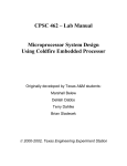
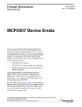
8.3.5.1 RESET STATUS REGISTER (RSR). The RSR contains a bit for each reset source
to the SIM. A bit set to 1 indicates the last type of reset that occurred. The RSR is updated
by the reset control logic when the reset is complete. Only one bit is set at any one time in
the RSR. The register reflects the cause of the most recent reset. If a reset occurs and you
have failed to clear this register, reset control logic clears any uncleared bits and set the bit
for the correct cause of reset. The illustration that follows shows the RSR programming
model.
This document contains information on a product under development. Motorola reserves the right to change or discontinue this product without notice.
SEMICONDUCTOR PRODUCT INFORMATION
1998 Motorola, Inc. All Rights Reserved.
Revision 0.4
The RSR is an 8-bit supervisor read-write register.
Reset Status Register(RSR)
Address MBAR + $000
7
6
5
4
3
2
1
0
HRST
-
SWTR
-
-
-
-
-
0
1/0
0
0
0
0
0
RESET:
1/0
Reset Status Register (RSR)
HRST - Hard Reset or System Reset
1 = An external device driving RSTI caused the last reset. Assertion of reset by an
external device causes the core processor to take a reset exception. All registers
in internal peripherals and the SIM are reset.
SWTR - Software Watchdog Timer Reset
1 = The last reset was caused by the software watchdog timer. If SWRI in the SYPCR is
set and the software watchdog timer times out, a hard reset occurs.
Table 8-5. SWT Timeout Period
SWP
SWT[1:0]
SWT TIMEOUT PERIOD
0
00
29 / System Frequency
0
01
211 / System Frequency
0
10
213 / System Frequency
0
11
215/ System Frequency
1
00
222 / System Frequency
1
01
224 / System Frequency
1
10
226 / System Frequency
1
11
228/ System Frequency
8.3.7 Bus Arbitration Control
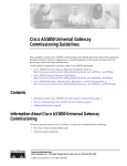
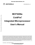
8.3.7.1 DEFAULT BUS MASTER REGISTER (MPARK). The MPARK determines the
Default Bus Master internal bus arbitration. Additionally, the MPARK configures internal
to external arbitration for internally generated transfers.Table 8-7 discusses the MPARK
bit encoding.
2
MCF5307 MASK SET ADDENDUM
MOTOROLA
The MPARK is an 8-bit read-write register.
Default Bus Master Register (MPARK):
7
6
5
PARK[1] PARK[0]
RESET:
0
0
Address MBAR + $0C
4
IARBCTRL EARBCTRL
0
0
3
2
1
SHOWDATA
-
-
0
0
0
0
BCR24BIT
0
Default Bus Master Register (MPARK)
The IARBCTRL bit controls access for external masters to the MCF5307 internal bus.
In a single master system, the IARBCTRL bit should remain cleared (0), disabling internal arbitration by external masters. In this scenario, the PARK[1:0] bits only apply to the
priority of internal masters over one another. Note that the internal DMA (master 3) has a
higher priority over the ColdFire core (master 2) if the internal DMA has its bandwidth
BWC[2:0] bits set to 000 (maximum bandwidth).
In multiple master systems that expect to use internal resources like the DRAM controller
or Chip selects, internal arbitration should be enabled by setting IARBCTRL to 1. The
external master defaults to the highest priority internal master anytime the bus grant signal is negated.
The EARBCTRL bit determines whether the internal bus masters, core processor and
internal DMA must arbitrate for the external bus for transfers that hit internal register
spaces (MBAR+register offset).
In a single-master system, setting or clearing EARBCTRL does not affect performance
with respect to arbitration. It is likely that the system designer has the BG signal tied low,
wherein the MCF5307 device always owns the externals bus and internal register transfers are already shown on the external bus. In a system where the MCF5307 device is
the only master, this bit may remain cleared to 0. If the system needs external visibility of
the data bus values during internal register transfers for system debug purposes, then
both EARBCTRL and the SHOWDATA bits must be set to 1. When an internal register
transfer is driven externally it is important to note that the XTA signal becomes an output
which is asserted (normally an input), to prevent external devices and memories from
responding to internal register transfers that go to the external bus. The AS signal and all
chip select-related strobe signals are not asserted.
In multiple master systems, disabling arbitration with the EARBCTRL bit allows performance improvement because internal register bus transfer cycles aren’t interfering with
the external bus. Having internal transfers go external affects performance in two possible ways. If the internal master doesn’t get the bus right away, the core is stalled until it
wins arbitration of the external bus; or if the core does win the arbitration instantly, it may
MOTOROLA
MCF5307 MASK SET ADDENDUM
3
kick the external master off the external bus unnecessarily for a transfer that didn’t need
the external bus in the first place. For debug, the EARBCTRL and SHOWDATA bits can
be set to 1, to gain external visibility of the internal bus cycles where this performance
penalty isn’t a concern.
Table 8-7. Default Bus Master Selected with PARK[1:0]
PARK[1:0]
DEFAULT BUS MASTER NUMBER
00
Round Robin between DMA and ColdFire Core
01
Park on external master 2 (ColdFire Core)
10
Park on external master 3 (Internal DMA)
11
Park on current master
Table 8-8. Round Robin (PARK[1:0] = 00)
MASTER NUMBER
PRIORITY
BUS MASTER NAME
2/3
Highest
Other Master
3/2
Lowest
Current Master
Table 8-9. Park on External Master 2 Priority (PARK[1:0] = 01)
MASTER NUMBER
PRIORITY
BUS MASTER NAME
2
Highest
ColdFire Core
3
Lowest
Internal DMA
Table 8-10. Park on External Master 3 Priority (PARK[1:0] = 10)
MASTER NUMBER
PRIORITY
BUS MASTER NAME
3
Highest
Internal DMA
2
Lowest
ColdFire Core
Table 8-11. Park on Current Master Priority (PARK[1:0] = 11)
MASTER NUMBER
PRIORITY
BUS MASTER NAME
2/3
Highest
Current Master
3/2
Lowest
Other Master
External Master Note: In all arbitration modes, if the bus
grant signal is negated, the external master interface has
highest priority. When this is the case, the ColdFire core is the
second highest, until bus grant asserts.
4
MCF5307 MASK SET ADDENDUM
MOTOROLA
Park on Current Master Note: When using the park on current master setting, the first master to arbitrate for the bus becomes the current master. The corresponding priority scheme
should be interpreted as the priority of the next master once
the current master finishes.
Important Note: IARBTRL must be set to 1 if external masters are using internal resources like the DRAM controller or
chip selects.
Additional Note: The Internal DMA (master 3) has higher priority than the ColdFire Core (master 2) if the internal DMA has
its bandwidth BWC[2:0] bits set to 000 (maximum bandwidth).
IARBCTRL - External to internal bus arbitration enable.
0 = Arbitration disabled
1 = Arbitration enabled
EARBCTRL - Enable internal register memory space to external bus arbitration.
0 = Arbitration disabled
1 = Arbitration enabled
EARBCTRL Note: Internal register memory space is considered all registers mapped off
the MBAR (MBAR+offset registers). These include the programming models for the SIM,
DMA, Chip Selects, Timers, UARTs, I2C, Parallel Port, etc.). It is important to note that
these registers don’t include the MBAR itself - only the core can access the MBAR.
SHOWDATA - Enable to drive Internal register data bus to external bus.
Note: The EARBCTRL bit must be set to 1 for this function to work.
0 = Don’t drive internal register data bus values to external bus
1 = Drive internal register data bus values to external bus
BCR24BIT - This bit controls the BCR and address mapping for the DMA. The bit allows
the byte count register to be used as a 24-bit register. See the DMA section for memory
maps and bit positions for the BCRs.
0 = DMA BCRs function as 16-bit counters.
1 = DMA BCRs function as 24-bit counters.
MOTOROLA
MCF5307 MASK SET ADDENDUM
5
SECTION 9: CHIP SELECT MODULE
9.1 INTRODUCTION
This section details the specification of the Chip Select Module (CS) for the MCF5307
device. The Chip Select Module provides user-programmable control of the eight chip
select outputs, four byte/byte-write enable outputs, and one output-enable signal.
This section also addresses the operation and programming model of the CS registers,
including the Chip Select Address, Mask and Control Registers.
9.1.1 Features
The following list summarizes the key chip select features:
• Eight programmable chip select signals
• Address masking for memory block sizes from 64K to 2G
• Programmable wait states and port sizes
• External master access to Chip selects
9.3 CHIP SELECT OPERATION
9.3.1 Chip Select Module
The Chip Select Module provides a glueless interface to many types of external memory.
The Chip Select Module includes the needed external control signals to interface to
SRAM, PROM, EPROM, EEPROM, FLASH and peripherals.
Each of the eight chip select outputs has an associated mask register and control register.
Chip selects (CS[7:0])
• Have individual 16-bit base address registers
• Have individual 32-bit mask register which provide for 16-bit address masking & access control.
• Have individual 16-bit control register which provides port size and burst capability
indication, wait state generation, and automatic acknowledge generation features.
• Can assert during specific CPU space accesses such as interrupt-acknowledge cycles.
Chip select 0 provides special functionality. It is a “global” chip select after reset and
provides relocatable boot ROM capability.
9.3.1.1 GENERAL CHIP SELECT OPERATION. The general-purpose Chip Selects are
controlled by the Chip Select Mask Register (CSMR), the Chip Select Control Register
(CSCR), and by the Chip Select Address Register (CSAR). There is one CSAR, CSMR
and CSCR for each of the Chip Selects (CS0-CS7).
6
MCF5307 MASK SET ADDENDUM
MOTOROLA
Chip Selects (CS[7:0])
• The chip select address register controls the base address space of the chip select.
• The chip select mask register controls the memory block size and addressing attributes of the chip select.
• The chip select control register programs the features of the chip s
elect signals.
9.4.1 Chip Select Registers Memory Map
Table 9-5 shows the memory map of all the Chip Select registers.
MOTOROLA
MCF5307 MASK SET ADDENDUM
7
Table 9-5. Memory Map of Chip Select Registers
8
RESET VALUE2
ADDRESS
NAME
WIDTH
DESCRIPTION
MBAR+$080
CSAR0
16
Chip Select Address Register - Bank 0
uninitialized
--
ACCESS3
R/W
MBAR+$082
--
16
Reserved1
MBAR+$084
CSMR0
32
Chip Select Mask Register - Bank 0
uninitialized
(except V=0)
MBAR+$088
--
16
Reserved1
--
R/W
R/W
-R/W
--
MBAR+$08A
CSCR0
16
Chip Select Control Register - Bank 0
BEM=1;
BSTR=BSTW=0;
AA=D[7]; PS1=D[6];
PS0=D[5];
WS3=WS2=WS1=WS0
=1
MBAR+$08C
CSAR1
16
Chip Select Address Register - Bank 1
uninitialized
MBAR+$08E
--
16
Reserved1
--
MBAR+$090
CSMR1
32
Chip Select Mask Register - Bank 1
uninitialized
(except V=0)
MBAR+$094
--
16
Reserved1
--
MBAR+$096
CSCR1
16
Chip Select Control Register - Bank 1
uninitialized
(except
BEM=BSTR=BSTW=0)
R/W
MBAR + $098
CSAR2
16
Chip Select Address Register - Bank 2
uninitialized
R/W
MBAR+ $09A
--
16
Reserved1
--
MBAR+$09C
CSMR2
32
Chip Select Mask Register - Bank 2
uninitialized
(except V=0)
MBAR+$A0
--
16
Reserved1
--
MBAR+$0A2
CSCR2
16
Chip Select Control Register - Bank 2
uninitialized
(except
BEM=BSTR=BSTW=0)
R/W
MBAR + $0A4
CSAR3
16
Chip Select Address Register - Bank 3
uninitialized
R/W
MBAR+$0A6
--
16
Reserved1
--
MBAR+$A8
CSMR3
32
Chip Select Mask Register - Bank 3
uninitialized
(except V=0)
MBAR+$0AC
--
16
Reserved1
--
MBAR+$0AE
CSCR3
16
Chip Select Control Register - Bank 3
uninitialized
(except
BEM=BSTR=BSTW=0)
R/W
MBAR + $0B0
CSAR4
16
Chip Select Address Register - Bank 4
uninitialized
R/W
MBAR+$0B2
--
16
Reserved1
--
MBAR+$0B4
CSMR4
32
Chip Select Mask Register - Bank 4
uninitialized
(except V=0)
MBAR+$0B8
--
16
Reserved1
--
MBAR+$0BA
CSCR4
16
Chip Select Control Register - Bank 4
uninitialized
(except
BEM=BSTR=BSTW=0)
R/W
MBAR+$0BC
CSAR5
16
Chip Select Address Register - Bank 5
uninitialized
R/W
MCF5307 MASK SET ADDENDUM
-R/W
--
-R/W
--
-R/W
--
-R/W
--
MOTOROLA
Table 9-5. Memory Map of Chip Select Registers (Continued)
RESET VALUE2
DESCRIPTION
ACCESS3
ADDRESS
NAME
WIDTH
MBAR+$0BE
--
16
Reserved1
--
MBAR+$0C0
CSMR5
32
Chip Select Mask Register - Bank 5
uninitialized
(except V=0
MBAR+$0C4
--
16
Reserved1
--
MBAR+$0C6
CSCR5
16
Chip Select Control Register - Bank 5
uninitialized
(except
BEM=BSTR=BSTW=0)
R/W
MBAR+$0C8
CSAR6
16
Chip Select Address Register - Bank 6
uninitialized
R/W
MBAR+$0CA
--
16
Reserved1
--
MBAR+$0CC
CSMR6
32
Chip Select Mask Register - Bank 6
uninitialized
(except V=0
MBAR+$0D0
--
16
Reserved1
--
MBAR+$0D2
CSCR6
16
Chip Select Control Register - Bank 6
uninitialized
(except
BEM=BSTR=BSTW=0)
R/W
MBAR+$0D4
CSAR7
16
Chip Select Address Register - Bank 7
uninitialized
R/W
MBAR+$0D6
--
16
Reserved1
--
MBAR+$0D8
CSMR7
32
Chip Select Mask Register - Bank 7
uninitialized
(except V=0
MBAR+$0DC
--
16
Reserved1
--
MBAR+$0DE
CSCR7
16
Chip Select Control Register - Bank 7
uninitialized
(except
BEM=BSTR=BSTW=0)
-R/W
--
-R/W
--
-R/W
-R/W
1. Addresses not assigned to a register and undefined register bits are reserved for future expansion. Write
accesses to these reserved address spaces and reserved register bits have no effect.
2. The reset value column indicates the register initial value at reset. Certain registers may be uninitialized
upon reset, i.e., they may contain random values.
3. The access column indicates whether the corresponding register allows both read/write functionality (R/W),
read-only functionality (R), or write-only functionality (W). A read access to a write-only register will return
zeros. A write access to a read-only register will have no effect.
9.4.1.1 GENERAL CHIP SELECT OPERATION. The general-purpose Chip selects are
controlled by the Chip Select Mask Register (CSMR), the Chip Select Control Register
(CSCR), and by the Chip Select Address Registers (CSAR). There is one CSAR, CSMR
and CSCR for each of the Chip selects (CS0-CS7).
Chip selects (CS[7:0])
• The chip select address register controls the base address space of the chip select.
• The chip select mask register controls the memory block size and addressing attributes of the chip select.
• The chip select control register programs the features of the chip select signals.
MOTOROLA
MCF5307 MASK SET ADDENDUM
9
The MCF5307 processor compares the address and mask in chip select 0 - 7 control
registers. If the address and attributes do not match in a single chip select register, the
MCF5307 runs an external bus cycle with external termination on a 32-bit port with burstinhibited transfers. Should an address and attribute match in multiple chip select registers,
the matching chip select signals are driven. Table 9-6 shows the type of access
depending on what matches are made in the CS control registers.
Table 9-6. Accesses by Matches in CS Control Registers
NUMBER OF CHIP SELECTS
REGISTER MATCHES
None
TYPE OF ACCESS
Single
External1
As defined by chip select control
register
Multiple
External1,2
9.4.2 Chip Select Module Registers
9.4.2.1 CHIP SELECT ADDRESS REGISTER (CSAR0 - CSAR7). Each CSAR and
CSBAR determines the base address of the corresponding chip select pin, and are read/
writeable.
• CSAR’s are 16-bit read/write registers.The value stored in each CSAR register corresponds to A[31:16].
• CSAR’s are uninitialized by reset
Chip Select Address Register for CS0 - CS7
15
14
13
12
11
10
9
8
7
6
5
4
3
2
1
0
BA31
BA30
BA29
BA28
BA27
BA26
BA25
BA24
BA23
BA22
BA21
BA20
BA19
BA18
BA17
BA16
-
-
-
-
-
-
-
-
-
-
-
-
-
-
-
RESET:
-
BA31-BA16 - Base Address
This field defines the base address location of memory dedicated to chip select CS[7:0].
These bits are compared to bits 31-16 on the internal core address bus to determine if the
chip select memory is being accessed.
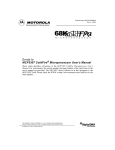
9.4.2.2 CHIP SELECT MASK REGISTER (CSMR0 - CSMR7). CSMR’s (read/writeable
registers) determine the address mask for CS[7:0], respectively. Also, CSMR[7:0]
determines the definition of which types of accesses are allowed for these signals. Each
CSMR is a 32-bit read/write control register that physically resides in the Chip Select
Module. CSMR7 - CSMR0 are uninitialized by reset, except for bit 0 (V-bit) which is
initialized to 0.
10
MCF5307 MASK SET ADDENDUM
MOTOROLA
Chip Select Mask Register (CSMR0-CSMR7)
31
30
29
28
27
26
25
24
23
22
21
20
19
18
17
16
BAM31 BAM30 BAM29 BAM28 BAM27 BAM26 BAM25 BAM24 BAM23 BAM22 BAM21 BAM20 BAM19 BAM18 BAM17 BAM16
RESET:
-
-
-
-
-
-
-
-
-
-
-
-
-
-
-
-
15
14
13
12
11
10
9
8
7
6
5
4
3
2
1
0
-
-
-
-
-
-
-
WP
-
EM
C/I
SC
SD
UC
UD
V
-
-
-
-
-
-
-
-
-
-
-
-
-
-
0
RESET:
-
BAM31-BAM16 - Base Address Mask
This field defines the chip select block size through the use of address mask bits. Any set
bit masks the corresponding base address register (CSAR) bit (the base address bit
becomes a don’t care in the decode).
0 = Corresponding address bit is used in chip select decode
1 = Corresponding address bit is a don’t care in chip select decode
The block size for CS[7:0] is equal to 2n, where n = (number of bits set in the base address
mask field of the respective CSMR)+16.
For example, if CSAR0 was set at $0000 and CSMR0 was set at $0008, then chip select
CS0 would address two 64K spaces: from $00000000 to $0000FFFF and from
$00080000 to $0008FFFF.
WP, EM, C/I, SC, SD, UC, UD - Write Protect, External Master, CPU/IACK, Supervisor
Code, Supervisor Data, User Code, User Data Address Space Mask
1. This field masks specific address spaces, placing the chip select in a specific address space or spaces. If an address space mask bit is cleared, an access to a location in that address space can activate the corresponding chip select. If an
address space mask bit is set, an access to a location in that address space becomes a regular external bus access, and no chip select is activated.
MOTOROLA
MCF5307 MASK SET ADDENDUM
11
For each address space mask bit (EM, C/I, SC, SD, UC, UD):
0 = Do not mask this address space for the chip select. An access using the chip select can occur for this address space.
1 = Mask this address space from the chip select activation. If this address space is
accessed, no chip select activation occurs on the external cycle.
The address space mask bits are:
WP= Write Protect
The WP bit can restrict write accesses to the address range in a CSAR. An attempt
to write to the range of addresses specified in a CSAR that has this bit set results
in the appropriate chip select not being selected. No exception occurs.
1 = Only read accesses are allowed
0 = Either read or write accesses are allowed
EM= External Master mask
When EM=0 and an external master access occurs, SC, SD, UC, and UD are “don’t
cares” in the chip select decode.
C/I = CPU space and Interrupt Acknowledge Cycle mask
SC = Supervisor Code address space mask
SD = Supervisor Data address space mask
UC = User Code address space mask
UD = User Data address space mask
V - Valid bit
The Valid bit indicates that the contents of its address register, mask register, and control
register are valid. The programmed chip selects do not assert until the V-bit is set (except
for CS0 which acts as the global (boot) chip select - see Global Chip Select Operation.
A reset clears the V-bit in each CSMR.
0 = Chip select invalid
1 = Chip select valid
9.4.2.4 CHIP SELECT CONTROL REGISTER (CSCR0 - CSCR7). Each CSCR controls
the auto acknowledge, external master support, port size, burst capability, and activation
of each of the Chip selects.
For CSCR1 - CSCR7, bits BSTR and BSTW are initialized to 0 by reset while all other bits
are uninitialized by reset. For CSCR0, bits BSTR, BSTW, and V are initialized to 0 by reset
while bits WS[3:0] are initialized to 1 by reset.
12
MCF5307 MASK SET ADDENDUM
MOTOROLA
CS0 is the global (boot) chip select and as such, allows address decoding for boot ROM
before system initialization occurs. Its operation differs from the other external chip select
outputs following a system reset.
Chip Select Control Register (CSCR0)
15
14
13
12
11
10
9
8
7
6
5
-
-
WS3
WS2
WS1
WS0
-
AA
PS1
PS0
BEM
-
1
1
1
1
-
D[7]
D[6]
D[5]
1
0
4
RESET:
-
4
3
2
1
0
-
-
-
0
-
-
-
3
2
1
0
-
-
-
-
-
-
BSTR BSTW
Chip Select Control Register (CSCR1-7)
15
14
13
12
11
10
9
8
7
6
5
-
-
WS3
WS2
WS1
WS0
-
AA
PS1
PS0
BEM
-
-
-
-
-
-
-
-
RESET:
-
0
BSTR BSTW
0
0
WS[3:0] - Wait States
This field defines the number of wait states that are inserted before an internal transfer
acknowledge is generated. If the AA bit is set to 0, TA is asserted by the external system
regardless of the number of wait states generated. In that case the external transfer
acknowledge ends the cycle.
BSTR - Burst Read Enable
This field specifies the read burst capability of the memory associated with each chipselect. If BSTR=1, all reads from port sizes smaller than the requested transfer size is
bursted, including longword reads from 8 and 16-bit ports, word reads from 8-bit ports as
well as line reads from 8-, 16-, and 32-bit ports. If BSTR=0, all reads from port sizes
smaller than the requested transfer size is broken into individual reads that are no larger
than the specified port size. For example, a longword read from an 8-bit port would be
broken into four individual byte reads.
0 = Break all reads that are larger than the specified port size into individual non-burst
reads that are no larger than the specified port size
1 = Allow burst read by Chip selected address space for all reads that are larger than
the specified port size
BSTW - Burst Write Enable
This field specifies the write burst capability of the memory associated with each chip
select. If BSTW=1, all writes to port sizes smaller than the requested transfer size are
bursted, including longword writes to 8 and 16-bit ports, word writes to 8-bit ports as well
as line writes to 8-, 16-, and 32-bit ports. If BSTW=0, all writes to port sizes smaller than
the requested transfer size are broken into individual writes that are no larger than the
MOTOROLA
MCF5307 MASK SET ADDENDUM
13
specified port size. For example, a longword write to an 8-bit port would be broken into
four individual byte writes.
0 = Break all writes that are larger than the specified port size into individual non-burst
writes that are no larger than the specified port size
1 = Allow burst write to Chip selected address space for all writes that are larger than
the specified port size
AA - Auto-Acknowledge Enable
This field controls the assertion of the internal transfer-acknowledge during all accesses
that hit in the corresponding chip select address space. If AA=1, the internal transferacknowledge is asserted at the time determined by the value of WS[3:0]. If AA=0, the Chip
Select Module does not cause the internal transfer acknowledge to be asserted and the
cycle has to be terminated by the external system.
0 = Wait for external transfer acknowledge
1 = Wait for internal acknowledge specified by WS[3:0]
PS[1:0] - Port Size
This field specifies the width of the data associated with each chip select. It determines
where data isdriven during write cycles and where data is sampled during read cycles.
00 = 32-bit port size - Data sampled and driven on D[31:0]
01 = 8-bit port size - Data sampled and driven on D[31:24] only
10 = 16-bit port size - Data sampled and driven on D[31:16] only
11 = 16-bit port size - Data sampled and driven on D[31:16] only
BEM - Byte Enable Module
This field specifies the mode of functionality for byte enables. Certain SRAMs have byte
enables that must be asserted during reads (in addition to writes.) The BEM bit may be
set in the relevant CSCR to provide the appropriate mode of byte enable in support of
these SRAMs. The default mode after reset is 0 for CS7 - CS1 and 1 for CS0.
1 = BE/BWE signals generated for data reads and writes
0 = BWE signals generated for data writes only
Note
Even if selected, BE is not asserted for writes.
9.4.2.5 CODE EXAMPLE. The code below provides an example of how to initialize the
chip- selects. MBARx defines the base of the module address space
CSAR0 EQU MBARx+$080 ;Chip Select 0 address register
CSMR0 EQU MBARx+$084 ;Chip Select 0 mask register
CSCR0 EQU MBARx+$08A ;Chip Select 0 control register
CSAR1 EQU MBARx+$08C ;Chip Select 1 address register
14
MCF5307 MASK SET ADDENDUM
MOTOROLA
CSMR1 EQU MBARx+$090 ;Chip Select 1 mask register
CSCR1 EQU MBARx+$096 ;Chip Select 1 control register
CSAR2 EQU MBARx+$098; Chip Select 2 address register
CSMR2 EQU MBARx+$09C ;Chip Select 2 mask register
CSCR2 EQU MBARx+$0A2 ;Chip Select 2 control register
CSAR3 EQU MBARx+$0A4; Chip Select 3 address register
CSMR3 EQU MBARx+$0A8 ;Chip Select 3 mask register
CSCR3 EQU MBARx+$0AE ;Chip Select 3 control register
CSAR4 EQU MBARx+$0B0: Chip Select 4 address register
CSAR4 EQU MBARx+$0B4 ;Chip Select 4 mask register
CSMR4 EQU MBARx+$0BA ;Chip Select 4 control register
CSAR5 EQU MBARx+$0BC:Chip Select 5 address register
CSMR5 EQU MBARx+$0C0 ;Chip Select 5 mask register
CSCR5 EQU MBARx+$0C6 ;Chip Select 5 control register
CSAR6 EQU MBARx+$0C8; Chip Select 6 address register
CSMR6 EQU MBARx+$0CC ;Chip Select 6 mask register
CSCR6 EQU MBARx+$0D2 ;Chip Select 6 control register
CSAR7 EQU MBARx+$0D4; Chip Select 7 address register
CSMR7 EQU MBARx+$0D8 ;Chip Select 7 mask register
CSCR7 EQU MBARx+$0DE ;Chip Select 7 control register
move.w
move.w
#$0000,D0
DO,CSAR0
;CSAR0 starts at address $00000000
;it is usually best to set up the cscr0 before exiting
move.w
move.w
global chip select
#$0C18,D0
;3 wait states, AA = 0, PS = 32-bit
DO,CSCR0
;BEM = 0, BURSTREAD = 1, BURSTWRITE = 1; This will exit
move.l
move.l
global chip select mode
#$00000001,D0 ;Addresses range from $00000000 to $0000FFFF
DO,CSMR0
; WP,AM,C/I,SC,SD,UC,UD =0; V = 1
move.w
move.w
#$0001,D0
DO,CSAR1
move.w
move.w
#$000F0001,D0 ;Addresses range from $00010000 to $000FFFFF
DO,CSMR1
; WP,AM,C/I,SC,SD,UC,UD =0; V = 1
move.w
move.w
#$0C18,D0
DO,CSCR1
MOTOROLA
;CSAR1 starts at address $00010000
;3 wait states, AA = 0, PS = 32-bit
;BEM = 0, BURSTREAD = 1, BURSTWRITE = 1
MCF5307 MASK SET ADDENDUM
15
SECTION 13: DMA CONTROLLER
Table 13-1. DMA Signals.
SIGNAL NAME
DIRECTION
DESCRIPTION
DREQ [1:0]
In
External DMA request
TT[1:0]
Out
Transfer Type
TM[2:0]
Out
Transfer Modifier
13.2.3 DMA Request (DREQ[1:0]/PP[6:5])
These multiplexed pins can serve as the DMA request inputs, or as two bits of the parallel
port. Programming the Pin Assignment Register (PAR) in the SIM determines the function
of each of these two multiplexed pins. You can program these pins on a bit-by-bit basis.
These active-low inputs are asserted by a peripheral device to request an operand
transfer between that peripheral and memory.
The DREQ signals are asserted to initiate DMA accesses in the respective channels. The
system should force any unused DREQ signals to a logic high state. Although each
channel has an individual DREQ pin, in the MCF5307 implementation only the DREQ for
channel 0 and 1 go to external pins. The DREQ for channel 2 and channel 3 are
connected to the internal interrupt pins of UART0 and UART1 respectively.
13.2.4 Transfer Type (TT[1:0]/PP[1:0])
These multiplexed pins serve to inform the system that an external master initiated the
access. The TM pin encodings are only meaningful when the TT signals are ‘01.
13.2.5 Transfer Modifier (TM[2:0]/PP[4:2])
These multiplexed pins serve to inform the system of attributes of the transfer. Table 132 shows the encodings for the TM pins when TT = ‘01, indicating that an external master
originated the transfer.
Table 13-2. TM Encoding for DMA as Master
TM
xx0
xx1
00x
01x
10x
11x
16
TRANSFER MODIFIER (TT = ‘01)
Single Address Access negated
Single Address Access
DMA Acknowledges negated
DMA Acknowledge, Channel 0
DMA Acknowledge, Channel 1
Reserved
MCF5307 MASK SET ADDENDUM
MOTOROLA
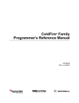
Note that Figure 13-5 is for BCR24BIT is 0. Figure 13-6 shows the differences in the
memory map when BCR24BIT = 1.
Base
Address
Offset
30C
34C
38C
3CC
[31:0]
Reserved
Byte Count Register 0
Reserved
Byte Count Register 1
Reserved
Byte Count Register 2
Reserved
Byte Count Register 3
Figure 13-6 DMA Controller Register Differences when BCR24BIT = 1
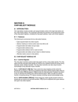
13.4.3 Byte Count Register (BCR)
The byte count register (BCR) is a 24-bit register containing the number of bytes
remaining to be transferred for a given block. The offset within the memory map is based
on the value of the BCR24BIT bit in the MPARK register. Bit locations are shown next.
Note that if the BCR24BIT is 0, the BCR is still 24 bits; the upper 8 bits are loaded with
zeros. The BCR decrements on the successful completion of the address phase of either
a write transfer in dual address mode or any transfer in single address mode. The amount
the BCR decrements is 1, 2, 4, or 16 for byte, word, longword, or line accesses,
respectively.
31
30
29
28
27
Reserved
26
25
24
23
22
21
20
19
18
17
16
BCR23 BCR22 BCR21 BCR20 BCR19 BCR18 BCR17 BCR16
Reset:
15
14
13
12
11
10
9
BCR15 BCR14 BCR13 BCR12 BCR11 BCR10 BCR9
Reset:
0
0
0
0
0
0
0
0
0
0
0
0
0
0
0
8
BCR8
7
BCR7
6
BCR6
5
BCR5
4
BCR4
3
BCR3
2
BCR2
1
BCR1
0
BCR0
0
0
0
0
0
0
0
0
0
Byte Count Register (BCR) - BCR24BIT = 1
31
30
29
28
27
26
25
BCR15 BCR4 BCR13 BCR12 BCR11 BCR10 BCR9
Reset:
0
0
0
0
0
0
0
24
BCR8
23
BCR7
22
BCR6
21
BCR5
20
BCR4
19
BCR3
18
BCR2
17
BCR1
16
BCR0
0
0
0
0
0
0
0
0
0
Byte Count Register (BCR) - BCR24BIT = 0
MOTOROLA
MCF5307 MASK SET ADDENDUM
17
13.4.4 DMA Control Register
The DMA control register (DCR) is a 16-bit register that controls the configuration of the
DMA Controller Module.
31
INT
Reset:
0
30
EEXT
29
CS
28
AA
27
26
BWC
25
0
0
0
15
AT
Reset:
0
14
13
12
24
SAA
23
S_RW
22
SINC
21
0
0
11
10
20
19
DINC
0
0
0
0
0
0
0
0
0
0
9
8
7
Reserved
6
5
4
3
2
1
0
SSIZE
18
17
DSIZE
16
START
N/A
Figure 13-1. DMA Control Register (DCR)—BCR24BIT = 1
31
INT
Reset:
0
30
EEXT
29
CS
28
AA
27
26
BWC
0
0
0
0
0
15
14
13
12
11
10
25
24
SAA
23
S_RW
22
SINC
21
20
0
0
0
0
0
0
0
0
0
0
9
8
7
Reserved
6
5
4
3
2
1
0
SSIZE
19
DINC
18
17
DSIZE
16
START
Reset:
N/A
Figure 13-2. DMA Control Register (DCR)—BCR24BIT = 0
BWC—Bandwidth Control
These three bits are decoded to provide for internal bandwidth control. When the byte
count has reached any multiple of the programmed BWC boundary, the request signal
to the internal arbiter is negated until the completion of the data access to enable the
arbiter to allow another master access to the bus.Table 13-3 shows the encodings for
these bits. When the bits are cleared, the DMA does not negate its request. The 000
encoding asserts a priority signal when the channel is active, signaling that the transfer
has been programmed for a higher priority. When the BCR reaches a multiple of the
values shown in the table, the bus is relinquished. For example, if BWC = 001,
BCR24BIT = 0, and the BCR is set to 516, the bus is relinquished after four bytes are
transferred. In another example, BWC = 110, BCR24BIT = 0, and the BCR is set to
33000. The bus is relinquished after transferring 232 bytes, since the BCR is at 32768,
which is a multiple of 16384.
START—Start Transfer
1 = Indicates to the DMA to begin the transfer according to the values in the control
registers. This bit is self-clearing after one clock and is always read as a logic 0.
18
MCF5307 MASK SET ADDENDUM
MOTOROLA
Table 13-3. BWC Encoding
BLOCK SIZE
BWC
BCR24BIT = 0
000
001
010
011
100
101
110
111
BCR24BIT = 1
DMA has priority
512
1024
2048
4096
8192
16384
32768
16384
32768
65536
131072
262144
524288
1048576
AT - DMA Acknowledge Type
1 = Indicates that the DMA acknowledge asserts only on the final transfer, i.e. the
BCR reaches 0. For dual address transfers, the acknowledge asserts for both
the read and write cycles.
0 = Indicates that the DMA acknowledge asserts for the entire transfer. The signal
asserts anytime the channel is selected as a result of an external request.
13.5.2 Continuous Mode
If the CS field in the DCR is cleared, the DMA is in continuous mode. After a request is
asserted, either internal or external, the DMA continuously transfers data until the BCR is
zero or the DONE bit in the DSR is set.
The continuous mode can be run at either the maximum rate or a limited rate. The
maximum rate of transfer can be achieved if the BWC field in the DCR is programmed to
be 000. Then the DMA channel that has started a transfer continues until the BCR
decrements to zero or a 1 is written to the DONE bit in the DSR.
A limited rate can be achieved by programming the BWC field to be anything except 000.
The DMA then performs the specified number of transfers and surrender the bus to allow
another device to use the bus. In this mode, the DMA negates its internal bus request on
the last transfer before the BCR reaches a multiple of the boundary programmed in the
BWC field. After the transfer is complete, it then asserts its bus request again to regain
mastership at the earliest possible time as determined by the internal bus arbiter. The
minimum amount of time that the DMA does not have the bus is one bus cycle.
13.5.3 Data Transfers
13.5.3.1 EXTERNAL REQUEST OPERATION. Each channel has the feature of
interfacing to an external module to initiate transfers to the module. In the MCF5307
device, the external requests for channel 0 and channel 1 are connected to external pins.
The request for channel 2 and channel 3 are connected internally to the slave bus
interrupt pins of the UART0 and UART1 modules, respectively. If the EEXT bit is set,
when the DREQ signal asserts, the DMA initiates a transfer provided the channel is idle.
If the CS (cycle steal) bit is set, a single read/write transfer occurs on the master bus. If
the CS bit is clear, multiple read/write transfers occur on the master bus as programmed
MOTOROLA
MCF5307 MASK SET ADDENDUM
19
in the BCR. The transfer mode pins can be used to provide an external DMA acknowledge
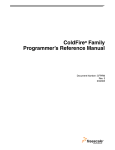
response. The DREQ signal is not required to be negated until the DONE bit of the DSR
asserts. In cycle-steal mode, the maximum length of DREQ assertion to maintain a single
transfer depends on configuration. In the worst case of a single-address access, no hold
signal, byte accesses, and idle channels, DREQ may be asserted for no more than four
rising clock edges (see Figure 13-7).
CLOCK
DREQ[1:0]
Figure 13-7. External Request Timing - Cycle-Steal Mode, Single-Address Mode
See Figure 13-8 for timing relationships for a dual-address transfer using cycle-steal
mode. The maximum assertion time for DREQ in this configuration is five clocks.
CLOCK
DREQ[1:0]
Figure 13-8. External Request Timing - Cycle-Steal Mode, Dual-Address Mode
When an access occurs that was initiated by an DREQ signal, the transfer type signals
indicates an external master cycle, while the transfer modifier signals, TM[2:1], indicates
that the cycle is due to an external request. These signals can be used to create two types
of acknowledge signal. Setting the AT bit of the DCR, causes the TM signal to assert
during the final transfer. Clearing the AT bit causes the TM signal to assert during all
externally requested accesses.
13.7.2.3 BANDWIDTH CONTROL. This feature provides a mechanism that can force the
DMA off the master bus, allowing another master access. This feature can simplify the
master bus arbiter design by making arbitration programmable. The decode of the BWC
provides 7 levels of block transfer sizes. If the BCR decrements to a value that is a multiple
of the decode of the BWC, the DMA master bus request negates until termination of the
bus cycle. The arbiter may then choose to switch the bus to another master, should a
request be pending. Note that if AA is set, the BCR may skip over the programmed
20
MCF5307 MASK SET ADDENDUM
MOTOROLA
boundary. In this case, the DMA master bus request does not negate. If the BWC = 0, the
request signal remains asserted until the BCR reaches 0. Note that in this arbitration
scheme, the arbiter can always force the DMA to relinquish the bus.
APPENDIX A: REGISTER MEMORY MAP
The following lists several keynotes regarding the Register Memory Map table:
• Bold letters mark registers that are restricted to supervisor access. While in user
mode, supervisor access registers can not be written. If a supervisor register is written to in user mode, the contents of the register are not changed. If a supervisor register is read in user mode, the data from the register are valid.
• Underlined letters mark registers which are status or event registers. In these registers, the SBC sets the bits and the users clear the registers. To clear a bit, the users
must write a one to that bit location; writing a zero has no effect.
• Normal letters mark registers which have accesses controlled by the address space
mask bits contained in the MBAR register (see next section).
• Addresses not assigned to a register and undefined register bits are reserved for future expansion. Write accesses to these reserved address spaces and reserved register bits have no effect.
Table A-1. Register Memory Map
ADDRESS
NAME
CPU @ $002
Cache Control Reg
BYTE0
BYTE1
CACR
CPU @ $004
Access Control Reg 0
ACR0
CPU @ $005
Access Control Reg 1
ACR1
BYTE2
BYTE3
SWIVR
SWSR
IRQPAR
Reserved
CPU @ $801
Vector Base Reg
VBR
CPU @ $C04
RAM Base Address Reg
RAMBAR
CPU @ $C0F
Module Base Address Reg
MBAR
MBAR + $000
System Control Reg
MBAR + $004
Pin Assignment Reg
RSR
SYPCR
PAR
MBAR + $008
PLL Control Reg
PLLCR
Reserved
MBAR + $00C
Bus Master Control Reg
MPARK
Reserved
MBAR + $010
-
MBAR + $014
-
MBAR + $018
-
MBAR + $01C
-
MBAR + $020
-
MBAR + $024
-
MBAR + $028
-
MBAR + $02C
-
MBAR + $030
-
MBAR + $034
-
MBAR + $038
-
MBAR + $03C
-
MOTOROLA
Reserved
MCF5307 MASK SET ADDENDUM
21
Table A-1. Register Memory Map (Continued)
ADDRESS
NAME
MBAR + $040
Interrupt Pending Reg
MBAR + $044
Interrupt Mask Reg
MBAR + $048
Auto Vector Control Reg
BYTE0
BYTE1
BYTE2
BYTE3
IPR
IMR
AVCR
Reserved
MBAR + $04C
Interrupt Control Reg
ICR0
ICR1
ICR2
ICR3
MBAR + $050
Interrupt Control Reg
ICR4
ICR5
ICR6
ICR7
MBAR + $054
Interrupt Control Reg
ICR8
ICR9
ICR10
ICR11
MBAR + $058
-
MBAR + $05C
-
MBAR + $060
-
MBAR + $064
-
MBAR + $068
-
MBAR + $06C
-
MBAR + $070
-
MBAR + $074
-
MBAR + $078
-
Reserved
MBAR + $07C
-
MBAR + $080
Chip Select Address Reg 0
Reserved
CSAR0
MBAR + $084
Chip Select Mask Reg 0
MBAR + $088
Chip Select Control Reg 0
Reserved
CSMR0
MBAR + $08C
Chip Select Address Reg 1
CSAR1
MBAR + $090
Chip Select Mask Reg 1
CSCR0
Reserved
CSMR1
MBAR + $094
Chip Select Control Reg 1
Reserved
CSCR1
MBAR + $098
Chip Select Address Reg 2
CSAR2
Reserved
MBAR + $09C
Chip Select Mask Registers
MBAR + $0A0
Chip Select Control Reg 2
Reserved
MBAR + $0A4
Chip Select Address Reg 3
CSAR3
MBAR + $0A8
Chip Select Mask Reg 3
CSMR2
CSCR2
Reserved
CSMR3
MBAR + $0AC
Chip Select Control Reg 3
Reserved
CSCR3
MBAR + $0B0
Chip Select Address Reg 4
CSAR4
Reserved
MBAR + $0B4
Chip Select Mask Reg 4
MBAR + $0B8
Chip Select Control Reg 4
Reserved
CSMR4
MBAR + $0BC
Chip Select Address Reg 5
CSAR5
MBAR + $0C0
Chip Select Mask Reg 5
CSCR4
Reserved
CSMR5
MBAR + $0C4
Chip Select Control Reg 5
Reserved
CSCR5
MBAR + $0C8
Chip Select Address Reg 6
CSAR6
Reserved
CSMR6
MBAR + $0CC
Chip Select Mask Reg 6
MBAR + $0D0
Chip Select Control Reg 6
Reserved
MBAR + $0D4
Chip Select Address Reg 7
CSAR7
MBAR + $0D8
Chip Select Mask Reg 7
MBAR + $0DC
Chip Select Control Reg 7
22
CSCR6
Reserved
CSMR7
Reserved
MCF5307 MASK SET ADDENDUM
CSCR7
MOTOROLA
Table A-1. Register Memory Map (Continued)
ADDRESS
NAME
MBAR + $0E0
-
MBAR + $0E4
-
MBAR + $0E8
-
MBAR + $0EC
-
MBAR + $0F0
-
MBAR + $0F4
-
MBAR + $0F8
-
BYTE0
BYTE1
BYTE2
Reserved
MBAR + $0FC
-
MBAR + $100
DRAMC Control Register
Reserved
DCR
MBAR + $104
-
Reserved
MBAR + $108
DRAMC Address & Control 0
DACR0
MBAR + $10C
DRAMC Mask Reg 0
DMR0
MBAR + $110
DRAMC Address & Control 1
DACR1
MBAR + $114
DRAMC Mask Reg 1
DMR1
MBAR + $118
-
MBAR + $11C
-
MBAR + $120
-
MBAR + $124
-
MBAR + $128
-
MBAR + $12C
-
MBAR + $130
-
MBAR + $134
-
MBAR + $138
-
Reserved
MBAR + $13C
-
MBAR + $140
Timer Mode Reg 0
MBAR + $144
Timer Reference Reg 0
TRR0
MBAR + $148
Timer Capture Reg 0
TCR0
MBAR + $14C
Timer Counter 0
MBAR + $150
Timer Event Reg 0
MBAR + $154
-
MBAR + $158
-
MBAR + $15C
-
MBAR + $160
-
MBAR + $164
-
MBAR + $168
-
MBAR + $16C
-
MBAR + $170
-
MBAR + $174
-
MBAR + $178
-
MBAR + $17C
-
MOTOROLA
BYTE3
TMR0
Reserved
TCN0
Reserved
TER0
Reserved
MCF5307 MASK SET ADDENDUM
23
Table A-1. Register Memory Map (Continued)
ADDRESS
NAME
MBAR + $180
Timer Mode Reg 1
MBAR + $184
Timer Reference Reg 1
TRR1
MBAR + $188
Timer Capture Reg 1
TCR1
MBAR + $18C
Timer Counter 1
MBAR + $190
Timer Event Reg 1
MBAR + $194
-
MBAR + $198
-
MBAR + $19C
-
MBAR + $1A0
-
MBAR + $1A4
-
MBAR + $1A8
-
MBAR + $1AC
-
MBAR + $1B0
-
MBAR + $1B4
-
MBAR + $1B8
-
BYTE0
BYTE1
BYTE2
BYTE3
TMR1
Reserved
TCN1
Reserved
TER1
Reserved
MBAR + $1BC
-
MBAR + $1C0
UART Mode Reg 0
MBAR + $1C4 UART Status 0/Clock Select Reg 10
UMR10/UMR20
USR0/UCSR0
MBAR + $1C8
UART Command Reg 0
UCR0
MBAR + $1CC
UART Receive 0/Transmit Buffer 0
URB0/UTB0
MBAR + $1D0 UART Change 0/Aux Control Reg 0 UIPCR0/UACR0
MBAR + $1D4 UART Interrupt Status 0/Mask Reg 0
UISR0/UIMR0
MBAR + $1D8 UART Baud Rate Generator MSB’s 0
UBG10
MBAR + $1DC UART Baud Rate Generator LSB’s 0
UBG20
MBAR + $1E0
-
MBAR + $1E4
-
MBAR + $1E8
-
Do
Not
Access
MBAR + $1EC
-
MBAR + $1F0
UART Interrupt Vector Reg 0
UIVR0
MBAR + $1F4
UART Input Port 0
UIP0
MBAR + $1F8
UART RTS Output Port 0
UOP10
MBAR + $1FC
UART Output Port 0
UOP00
24
Reserved
MCF5307 MASK SET ADDENDUM
MOTOROLA
Table A-1. Register Memory Map (Continued)
ADDRESS
NAME
BYTE0
MBAR + $200
UART Mode Reg 1
UMR11/UMR21
BYTE1
MBAR + $204
UART Status 1/Clock Select Reg 1
USR1/UCSR1
MBAR + $208
UART Command Reg 1
UCR1
MBAR + $20C
UART Receive 1/Transmit Buffer 1
URB1/UTB1
MBAR + $210
UART Change 1/Aux Control Reg 1 UIPCR1/UACR1
MBAR + $214 UART Interrupt Status 1/Mask Reg 1
UISR1/UIMR1
MBAR + $218 UART Baud Rate Generator MSB’s 1
UBG11
MBAR + $21C UART Baud Rate Generator LSB’s 1
UBG21
MBAR + $220
-
MBAR + $224
-
MBAR + $228
-
BYTE2
BYTE3
Reserved
Do
Not
Access
MBAR + $22C
-
MBAR + $230
UART Interrupt Vector Reg 1
UIVR1
MBAR + $234
UART Input Port 1
UIP1
MBAR + $238
UART RTS Output Port 1
UOP11
MBAR + $23C
UART Output Port 1
UOP01
MBAR + $240
-
MBAR + $244
Parallel Port Data Direction Reg
PADDR
MBAR + $248
Parallel Port Data Reg
PADAT
MBAR + $24C
-
MBAR + $250
-
Reserved
Reserved
MBAR + $254
MBAR + $258
-
MBAR + $25C
-
MBAR + $260
Reserved
MBAR + $264
MBAR + $268
-
MBAR + $26C
-
MBAR + $270
-
MBAR + $274
MBAR + $278
-
MBAR + $27C
-
MBAR + $280
M-Bus Address Reg
MBAR + $284
M-Bus Frequency Reg
MFDR
MBAR + $288
M-Bus Control Reg
MBCR
MBAR + $28C
M-Bus Status Reg
MBSR
MBAR + $290
M-Bus Data Reg
MBDR
MOTOROLA
MADR
MCF5307 MASK SET ADDENDUM
Reserved
25
Table A-1. Register Memory Map (Continued)
ADDRESS
NAME
MBAR + $294
-
MBAR + $298
-
MBAR + $29C
-
MBAR + $2A0
-
MBAR + $2A4
-
MBAR + $2A8
-
MBAR + $2AC
-
MBAR + $2B0
-
MBAR + $2B4
-
MBAR + $2B8
-
MBAR + $2BC
-
MBAR + $2C0
-
MBAR + $2C4
-
MBAR + $2C8
-
MBAR + $2CC
-
MBAR + $2D0
-
MBAR + $2D4
-
MBAR + $2D8
-
MBAR + $2DC
-
MBAR + $2E0
-
MBAR + $2E4
-
MBAR + $2E8
-
MBAR + $2EC
-
MBAR + $2F0
-
MBAR + $2F4
-
MBAR + $2F8
-
MBAR + $2FC
-
BYTE0
BYTE1
BYTE2
Reserved
MBAR + $300
DMA Source Add Reg 0
SAR0
MBAR + $304
DMA Destination Addr Reg 0
DAR0
MBAR + $308
DMA Control Reg 0
DCR0
MBAR + $30C
DMA Byte Count Reg 0
BCR0
MBAR + $310
DMA Statue Reg 0
DSR0
MBAR + $314
DMA Vector Reg 0
DIVR0
MBAR + $318
-
MBAR + $31C
-
MBAR + $320
-
MBAR + $324
-
MBAR + $328
-
MBAR + $32C
-
MBAR + $330
-
MBAR + $334
-
MBAR + $338
-
MBAR + $33C
-
26
BYTE3
Reserved
Reserved
MCF5307 MASK SET ADDENDUM
MOTOROLA
Table A-1. Register Memory Map (Continued)
ADDRESS
NAME
MBAR + $340
DMA Source Add Reg 1
BYTE0
BYTE1
BYTE2
MBAR + $344
DMA Destination Addr Reg 1
DAR1
MBAR + $348
DMA Control Reg 1
DCR1
MBAR + $34C
DMA Byte Count Reg 1
MBAR + $350
DMA Statue Reg 1
DSR1
MBAR + $354
DMA Vector Reg 1
DIVR1
MBAR + $358
-
MBAR + $35C
-
MBAR + $360
-
MBAR + $364
-
MBAR + $368
-
MBAR + $36C
-
MBAR + $370
-
MBAR + $374
-
MBAR + $378
-
BCR1
Reserved
Reserved
MBAR + $37C
-
MBAR + $380
DMA Source Add Reg 2
MBAR + $384
DMA Destination Addr Reg 2
DAR2
MBAR + $388
DMA Control Reg 2
DCR2
MBAR + $38C
DMA Byte Count Reg 2
MBAR + $390
DMA Statue Reg 2
DSR2
MBAR + $394
DMA Vector Reg 2
DIVR2
MBAR + $398
-
MBAR + $39C
-
MBAR + $3A0
-
MBAR + $3A4
-
MBAR + $3A8
-
MBAR + $3AC
-
MBAR + $3B0
-
MBAR + $3B4
-
MBAR + $3B8
-
SAR2
BCR2
Reserved
Reserved
MBAR + $3BC
-
MBAR + $3C0
DMA Source Add Reg 3
MBAR + $3C4
DMA Destination Addr Reg 3
DAR3
MBAR + $3C8
DMA Control Reg 3
DCR3
MBAR + $3CC
DMA Byte Count Reg 3
MBAR + $3D0
DMA Statue Reg 3
DSR3
MBAR + $3D4
DMA Vector Reg 3
DIVR3
MOTOROLA
BYTE3
SAR1
SAR3
BCR3
MCF5307 MASK SET ADDENDUM
Reserved
27
Table A-1. Register Memory Map (Continued)
ADDRESS
NAME
MBAR + $3D8
-
MBAR + $3DC
-
MBAR + $3E0
-
MBAR + $3E4
-
MBAR + $3E8
-
MBAR + $3EC
-
MBAR + $3F0
-
MBAR + $3F4
-
MBAR + $3F8
-
MBAR + $3FC
-
28
BYTE0
BYTE1
BYTE2
BYTE3
Reserved
MCF5307 MASK SET ADDENDUM
MOTOROLA
APPENDIX B
MCF 5307 MEMORY MAP SUMMARY
This table below is a summary chart of the entire memory map for the MCF5307.
Table B-1. MCF5307 User Programming Model
ADDRESS
NAME
WIDTH
DESCRIPTION
MBAR+$000
MBAR+$001
MBAR+$002
MBAR+$003
MBAR+$004
MBAR+$006
MBAR+$008
MBAR+$00C
RSR
SYPCR
SWIVR
SWSR
PAR
IRQPAR
PLLCR
MARBCR
8
8
8
8
16
8
8
8
RESET STATUS REGISTER
SYSTEM PROTECTION CONTROL REGISTER
SOFTWARE WATCHDOG INTERRUPT VECTOR REGISTER
SOFTWARE WATCHDOG SERVICE REGISTER
PIN ASSIGNMENT REGISTER
INTERRUPT ASSIGNEMENT REGISTER
PLL CONTROL REGISTER
MARB CONTROL REGISTER
$80 OR $20
$00
$0F
uninitialized
$0000
$00
$00
$00
R/W
R/W
R/W
W
R/W
R/W
R/W
R/W
MBAR+$040
MBAR+$044
MBAR+$04B
MBAR+$04C
MBAR+$04D
MBAR+$04E
MBAR+$04F
MBAR+$050
MBAR+$051
MBAR+$052
MBAR+$053
MBAR+$054
MBAR+$055
MBAR+$056
MBAR+$057
IPR
IMR
AVCR
ICR0
ICR1
ICR2
ICR3
ICR4
ICR5
ICR6
ICR7
ICR8
ICR9
ICR10
ICR11
32
32
8
8
8
8
8
8
8
8
8
8
8
8
8
INTERRUPT PENDING REGISTER
INTERRUPT MASK REGISTER
AUTOVECTOR CONTROL REGISTER
INTERRUPT CONTROL REGISTER 0
INTERRUPT CONTROL REGISTER 1
INTERRUPT CONTROL REGISTER 2
INTERRUPT CONTROL REGISTER 3
INTERRUPT CONTROL REGISTER 4
INTERRUPT CONTROL REGISTER 5
INTERRUPT CONTROL REGISTER 6
INTERRUPT CONTROL REGISTER 7
INTERRUPT CONTROL REGISTER 8
INTERRUPT CONTROL REGISTER 9
INTERRUPT CONTROL REGISTER 10
INTERRUPT CONTROL REGISTER 11
$00000000
$0000FFFE
$00
$00
$00
$00
$00
$00
$00
$00
$00
$00
$00
$00
$00
R/W
R/W
R/W
R/W
R/W
R/W
R/W
R/W
R/W
R/W
R/W
R/W
R/W
R/W
R/W
MBAR+$080 CSAR0
16
Chip Select Address Register - Bank 0
uninitialized
MBAR+$082
16
Reserved1
--
MBAR+$084 CSMR0
32
Chip Select Mask Register - Bank 0
uninitialized
(except V=0)
MBAR+$088
16
Reserved1
--
--
--
RESET VALUE ACCESS
16
Chip Select Control Register - Bank 0
MBAR+$08C CSAR1
16
Chip Select Address Register - Bank 1
BEM=1;
BSTR=BSTW=0;
AA=D[7];
PS1=D[6];
PS0=D[5];
WS3=WS2=WS1
=WS0=1
uninitialized
MBAR+$08E
16
Reserved1
--
MBAR+$090 CSMR1
32
Chip Select Mask Register - Bank 1
uninitialized
(except V=0)
MBAR+$094
16
Reserved1
--
Chip Select Control Register - Bank 1
uninitialized
(except
BEM=BSTR=BST
W=0)
MBAR+$08A CSCR0
--
--
MBAR+$096 CSCR1
MOTOROLA
16
MCF5307 MASK SET ADDENDUM
R/W
-R/W
--
R/W
R/W
-R/W
-R/W
29
Table B-1. MCF5307 User Programming Model
ADDRESS
NAME
MBAR + $098 CSAR2
WIDTH
DESCRIPTION
RESET VALUE ACCESS
16
Chip Select Address Register - Bank 2
uninitialized
16
Reserved1
--
32
Chip Select Mask Register - Bank 2
uninitialized
(except V=0)
16
Reserved1
--
MBAR+$0A2 CSCR2
16
Chip Select Control Register - Bank 2
MBAR + $0A4 CSAR3
16
Chip Select Address Register - Bank 3
uninitialized
(except
BEM=BSTR=BST
W=0)
uninitialized
16
Reserved1
--
32
Chip Select Mask Register - Bank 3
uninitialized
(except V=0)
16
Reserved1
--
MBAR+ $09A
--
MBAR+$09C CSMR2
MBAR+$A0
MBAR+$0A6
--
--
MBAR+$A8 CSMR3
MBAR+$0AC
--
R/W
-R/W
--
R/W
--
16
Chip Select Control Register - Bank 3
MBAR + $0B0 CSAR4
16
Chip Select Address Register - Bank 4
MBAR+$0B2
16
Reserved1
--
MBAR+$0B4 CSMR4
32
Chip Select Mask Register - Bank 4
uninitialized
(except V=0)
MBAR+$0B8
16
Reserved1
--
MBAR+$0BA CSCR4
16
Chip Select Control Register - Bank 4
MBAR+$0BC CSAR5
16
Chip Select Address Register - Bank 5
uninitialized
(except
BEM=BSTR=BST
W=0)
uninitialized
16
Reserved1
--
MBAR+$0BE
--
--
--
MBAR+$0C4
16
Reserved1
--
16
Chip Select Control Register - Bank 5
MBAR+$0C8 CSAR6
16
Chip Select Address Register - Bank 6
uninitialized
(except
BEM=BSTR=BST
W=0)
uninitialized
MBAR+$0CA
16
Reserved1
--
MBAR+$0CC CSMR6
32
Chip Select Mask Register - Bank 6
uninitialized
(except V=0
MBAR+$0D0
16
Reserved1
--
--
--
--
Chip Select Control Register - Bank 6
MBAR+$0D4 CSAR7
16
Chip Select Address Register - Bank 7
16
Reserved1
--
32
Chip Select Mask Register - Bank 7
MBAR+$0DC
16
Reserved1
--
--
MCF5307 MASK SET ADDENDUM
R/W
R/W
16
MBAR+$0D8 CSMR7
R/W
--
MBAR+$0D2 CSCR6
uninitialized
(except V=0
R/W
R/W
uninitialized
(except
BEM=BSTR=BST
W=0)
uninitialized
--
R/W
--
Chip Select Mask Register - Bank 5
MBAR+$0D6
30
--
32
--
R/W
R/W
MBAR+$0C0 CSMR5
MBAR+$0C6 CSCR5
R/W
--
uninitialized
(except V=0
--
R/W
--
uninitialized
(except
BEM=BSTR=BST
W=0)
uninitialized
MBAR+$0AE CSCR3
R/W
R/W
R/W
-R/W
--
MOTOROLA
Table B-1. MCF5307 User Programming Model
ADDRESS
NAME
WIDTH
DESCRIPTION
MBAR+$0DE CSCR7
16
Chip Select Control Register - Bank 7
MBAR+$100
DCR
16
DRAMC CONTROL REGISTER
MBAR+$108
DACR0
32
DRAMC0 ADDRESS & CONTROL REGISTER
MBAR+$10C
DMR0
32
DRAMC0 MASK REGISTER
MBAR+$110
DACR1
32
DRAMC1 ADDRESS & CONTROL REGISTER
MBAR+$114
DMR1
32
DRAMC1 MASK REGISTER
MBAR+$140
MBAR+$144
MBAR+$148
MBAR+$14C
MBAR+$151
MBAR+$180
MBAR+$184
MBAR+$188
MBAR+$18C
MBAR+$191
TMR1
TRR1
TCR1
TCN1
TER1
TMR2
TRR2
TCR2
TCN2
TER2
16
16
16
16
8
16
16
16
16
8
TIMER1 MODE REGISTER
TIMER1 REFERENCE REGISTER
TIMER1 CAPTURE REGISTER
TIMER1 COUNTER RETGISTER
TIMER1 EVENT REGISTER
TIMER2 MODE REGISTER
TIMER2 REFERENCE REGISTER
TIMER2 CAPTURE REGISTER
TIMER2 COUNTER RETGISTER
TIMER2 EVENT REGISTER
MBAR+$1C0
MBAR+$1C0
MBAR+$1C4
MBAR+$1C4
MBAR+$1C8
MBAR+$1CC
MBAR+$1CC
MBAR+$1D0
MBAR+$1D0
MBAR+$1D4
MBAR+$1D4
MBAR+$1D8
MBAR+$1DC
MBAR+$1F0
MBAR+$1F4
MBAR+$1F8
UMR11
UMR21
USR1
UCSR1
UCR1
URB1
UTB1
UIPCR1
UACR1
UISR1
UIMR1
UBG11
UBG21
UIVR1
UIP1
UOP11
8
8
8
8
8
8
8
8
8
8
8
8
8
8
8
8
UART1 MODE REGISTER
UART1 MODE REGISTER
UART1 STATUS REGISTER
UART1 CLOCK SELECT REGISTER
UART1 COMMAND REGISTER
UART1 RECEIVE BUFFER REGISTER
UART1 TRANSMIT BUFFER REGISTER
UART1 INPUT PORT CHANGE REGISTER
UART1 AUCILARY CONTROL REGISTER
UART1 INTERRUPT STATUS REGISTER
UART1 INTERRUPT MASK REGISTER
UART1 BUAD RATE PRESCALE (MSB) REGISTER
UART1 BUAD RATE PRESCALE (LSB) REGISTER
UART1 INTERRUPT VECTOR REGISTER
UART1 INTERRPUT PORT REGISTER
UART1 OUTPUT PORT BIT SET REGISTER
MBAR+$1FC
UOP01
8
UART1 OUTPUT PORT BIT RESET REGISTER
MBAR+$200
MBAR+$200
MBAR+$204
MBAR+$204
MBAR+$208
MBAR+$20C
MBAR+$20C
MBAR+$210
UMR12
UMR22
USR2
UCSR2
UCR2
URB2
UTB2
UIPCR2
8
8
8
8
8
8
8
8
UART2 MODE REGISTER
UART2 MODE REGISTER
UART2 STATUS REGISTER
UART2 CLOCK SELECT REGISTER
UART2 COMMAND REGISTER
UART2 RECEIVE BUFFER REGISTER
UART2 TRANSMIT BUFFER REGISTER
UART2 INPUT PORT CHANGE REGISTER
MOTOROLA
MCF5307 MASK SET ADDENDUM
RESET VALUE ACCESS
uninitialized
(except
BEM=BSTR=BST
W=0)
R/W
uninitialized (except
[15] = 0)
uninitialized (except
[15] = 0)
uninitialized (except
[0] = 0)
uninitialized (except
[15] = 0)
uninitialized (except
[0] = 0)
R/W
$0000
$FFFF
$0000
$0000
$00
$0000
$FFFF
$0000
$0000
$00
R/W
R/W
R
R/W
R/W
R/W
R/W
R
R/W
R/W
$00
$00
$00
$DD
$00
$FF
$00
$0F
$00
$00
$00
uninitialized
uninitialized
$0F
$FF
[7:1]=undefined,[0]
= $0
uninitialized
R/W
R/W
R
W
W
R
W
R
W
R
W
W
W
R/W
R
W
$00
$00
$00
$DD
$00
$FF
$00
$0F
R/W
R/W
R
W
W
R
W
R
R/W
R/W
R/W
R/W
W
31
Table B-1. MCF5307 User Programming Model
NAME
WIDTH
MBAR+$210
MBAR+$214
MBAR+$214
MBAR+$218
MBAR+$21C
MBAR+$230
MBAR+$234
MBAR+$238
ADDRESS
UACR2
UISR2
UIMR2
UBG12
UBG22
UIVR2
UIP2
UOP12
8
8
8
8
8
8
8
8
UART2 AUCILARY CONTROL REGISTER
UART2 INTERRUPT STATUS REGISTER
UART2 INTERRUPT MASK REGISTER
UART2 BUAD RATE PRESCALE (MSB) REGISTER
UART2 BUAD RATE PRESCALE (LSB) REGISTER
UART2 INTERRUPT VECTOR REGISTER
UART2 INTERRPUT PORT REGISTER
UART2 OUTPUT PORT BIT SET REGISTER
DESCRIPTION
MBAR+$23C
UOP02
8
UART2 OUTPUT PORT BIT RESET REGISTER
MBAR+$244
MBAR+$248
PADDR
PADAT
16
16
PARALLEL PORT DATA DIRECTION REGISTER
PARALLEL PORT DATA REGISTER
MBAR+$280
MBAR+$284
MBAR+$288
MBAR+$28C
MBAR+$290
MADR
MFDR
MBCR
MBSR
MBDR
8
8
8
8
8
MBUS ADDRESS REGISTER
MBUS FREQUENCY REGISTER
MBUS CONTROL REGISTER
MBUS STATUS REGISTER
MBUS DATA REGISTER
MBAR+$300
MBAR+$304
MBAR+$308
MBAR+$30C
MBAR+$310
MBAR+$314
SAR0
DAR0
DCR0
BCR0
DSR0
DIVR0
32
32
32
32
8
8
MBAR+$340
MBAR+$344
MBAR+$348
MBAR+$34C
MBAR+$350
MBAR+$354
SAR1
DAR1
DCR1
BCR1
DSR1
DIVR1
MBAR+$380
MBAR+$384
MBAR+$388
MBAR+$38C
MBAR+$390
MBAR+$394
MBAR+$3C0
MBAR+$3C4
MBAR+$3C8
MBAR+$3CC
MBAR+$3C0
MBAR+$3D4
RESET VALUE ACCESS
$00
$00
$00
uninitialized
uninitialized
$0F
$FF
[7:1]=undefined,[0]
= $0
uninitialized
W
R
W
W
W
R/W
R
W
$0000
$0000
R/W
R/W
$00
$00
$00
$00
$00
R/W
R/W
R/W
R/W
R/W
DMA SOURCE ADDRESS REGISTER 0
DMA DESTINATION ADDRESS REGISTER 0
DMA CONTROL REGISTER 0
DMA BYTE COUNT REGISTER 0
DMA STATUS REGISTER 0
DMA INTERRUPT VECTOR REGISTER 0
$00000000
$00000000
$0000
$0000
$00
$00
R/W
R/W
R/W
R
R
R/W
32
32
32
32
8
8
DMA SOURCE ADDRESS REGISTER 1
DMA DESTINATION ADDRESS REGISTER 1
DMA CONTROL REGISTER 1
DMA BYTE COUNT REGISTER 1
DMA STATUS REGISTER 1
DMA INTERRUPT VECTOR REGISTER 1
$00000000
$00000000
$0000
$0000
$00
$00
R/W
R/W
R/W
R
R
R/W
SAR2
DAR2
DCR2
BCR2
DSR2
DIVR2
32
32
32
32
8
8
DMA SOURCE ADDRESS REGISTER 2
DMA DESTINATION ADDRESS REGISTER 2
DMA CONTROL REGISTER 2
DMA BYTE COUNT REGISTER 2
DMA STATUS REGISTER 2
DMA INTERRUPT VECTOR REGISTER 2
$00000000
$00000000
$0000
$0000
$00
$00
R/W
R/W
R/W
R
R
R/W
SAR3
DAR3
DCR3
BCR3
DSR3
DIVR3
32
32
32
32
8
8
DMA SOURCE ADDRESS REGISTER 3
DMA DESTINATION ADDRESS REGISTER 3
DMA CONTROL REGISTER 3
DMA BYTE COUNT REGISTER 3
DMA STATUS REGISTER 3
DMA INTERRUPT VECTOR REGISTER 3
$00000000
$00000000
$0000
$0000
$00
$00
R/W
R/W
R/W
R
R
R/W
W
The table below is a summary chart of the entire internal CPU memory map for the
MCF5307. These registers are addressed with the MOVEC command.
32
MCF5307 MASK SET ADDENDUM
MOTOROLA
Table B-2.
ADDRESS
CPU @ $002
CPU @ $004
CPU @ $005
CPU @ $801
CPU @ $c04
CPU @ $c0f
WIDTH
NAME
32
CACR
32
ACR0
32
ACR1
32
VBR
32
RAMBAR
32
MBAR
DESCRIPTION
Cache Control Register
Access Control Register 0
Access Control Register 1
Vector Base Register
RAM Base Address Register
Module Base Address Register
RESET VALUE
ACCESS
$0000000
W
$0000000
W
$0000000
W
$0000000
W
$0000000
W
$0000000
W
Table 2 provides the internal location for the base registers and the cache control registers
for the MCF5307. Most compilers and assemblers recognize the register name (i.e.
MBAR, CACR) and will automatically place the correct internal CPU address in the opcode. There is no need to define the registers at their respective CPU address locations.
Below are some examples of how the programmer would use the MOVEC command for
the some of the above listed registers:
;Example code:
;****SRAM SETUP***
move.l
$00010000+1,DO
movec
D0,RAMBAR
;****MBAR SETUP***
move.l
$10000000,DO
movec
D0,MBAR
;****VBR SETUP***
move.l
$00200000,DO
movec
D0,VBR
MOTOROLA
;SRAM base = $10000 and set the V bit
;bits [5:1] set to 0
;Module base = $10000000 and set the V bit
;bits [4:1] set to 0
;Interrupt vector base = $200000
MCF5307 MASK SET ADDENDUM
33
ADDITIONAL FUNCTIONALITY ON J20C MASK
APPENDIX C: MULTIPLY-ACCUMULATE UNIT
This section details the functionality, microarchitecture and performance of the hardware
multiply-accumulate (MAC) unit in the ColdFire family of processors.
The design of the MAC unit is centered around the notion of providing a limited set of DSP
operations that are currently being used in embedded code today, while supporting the
integer multiply instructions of the baseline ColdFire architecture.
The MAC unit provides functionality in three related areas:
- Signed and unsigned integer multiplies
- Multiply-accumulate operations supporting signed and unsigned integer operands as
well as signed, fixed-point, fractional operands
- Miscellaneous register operations
In particular, this revision of the specification details the enhanced functionality related to
support of signed fractional operands. The initial design and implementation of the
ColdFire MAC unit supported signed and unsigned integer operands. Using the so-called
Q notation, input operands can be scaled to the required precision. The initial
implementation was optimized for 16x16 operations, based on a variety of target
applications including servo control, imaging compression, etc. As additional system
designers implemented ColdFire-based systems, the desire for more precision on the
input operands was voiced. The result is an enhanced ColdFire MAC unit with userprogrammable control to optionally enable the use of fractional input operands. The
revised specification is fully backward-compatible with the original MAC design, and
provides a significant increase in available numerical precision.
Each of the three areas of support is addressed in detail in the succeeding sections.
The logic required to support this functionality is contained in a MAC Module, as shown
below.
34
MCF5307 MASK SET ADDENDUM
MOTOROLA
Operand Y
Operand X
X
Shift 0,1,-1
+/-
Accumulator
Multiply-Accumulate Functionality Diagram
C.1 AN INTRODUCTION TO THE MAC UNIT
The multiply-accumulate (MAC) unit is an extension of the basic multiplier structure found
in almost all microprocessors in the market today, whether implemented in hardware or
some type of iterative routine within an architecture itself. The idea behind this extension
is to provide the ability to do operations native to signal processing algorithms in an
acceptable number of cycles, given the constraints of the application. For example, small
digital filters can certainly tolerate some variance in the execution time of the algorithm;
larger, more complicated algorithms such as orthogonal transforms may have more
demanding speed requirements and may be beyond the scope of any processor
architecture and require a full-blown DSP implementation.
Obviously, the M68000 architecture was not designed for high-speed signal processing,
and a large DSP engine would be excessive in an embedded environment. In striking a
middle ground between speed, size and functionality, the ColdFire MAC unit is optimized
for a small set of operations that involve multiplication and cumulative additions.
Specifically, the multiplier array is optimized for single-cycle 16x16 multiplies producing a
32-bit result, with a possible accumulation cycle following. As it turns out, this is common
in a large portion of signal processing applications. In addition, the ColdFire core
architecture has been modified to allow for an operand fetch in parallel with a multiply,
resulting in an overall increase in performance for certain DSP operations.
MOTOROLA
MCF5307 MASK SET ADDENDUM
35
C.2 GENERAL OPERATION
The MAC unit is designed to support the ColdFire integer multiply instructions (MULS and
MULU) and provide additional functionality for multiply-accumulate operations. The added
MAC instructions to the ColdFire ISA provide for the multiplication of two numbers,
followed by the addition/subtraction of this number to/from the value contained in the
accumulator. The product may be optionally shifted left or right one bit before the addition
or subtraction takes place. Hardware support for saturation arithmetic may be enabled to
minimize software overhead when dealing with potential overflow conditions using signed
or unsigned operands.
These multiply-accumulate operations treat the operands as one of the following formats:
• Signed integers
• Unsigned integers
• Signed, fixed-point, fractional numbers
The MAC module has been optimized for 16-bit multiplications in order to keep the area
consumption low. Two 16-bit operands produce a 32-bit product. Longword operations
are performed by reusing the 16-bit multiplier array at the expense of a small amount of
extra control logic. Again, the product of two 32-bit operands is a 32-bit result. For
longword integer operations, only the least significant 32 bits of the product are calculated.
For fractional operations, the entire 63-bit product is calculated and then either truncated
or rounded to a 32-bit result using the round-to-nearest (even) method.
Since the multiplier array is implemented in a 3-stage pipeline, the MAC instructions have
an effective issue rate of one clock for word operations, three clocks for longword integer
operations, and four clocks for 32-bit fractional operations. All arithmetic operations use
register-based input operands, and summed values are stored internally in the
accumulator. Thus, an additional move instruction is necessary to store the data in a
general-purpose register. One feature new to the MAC instructions is the ability to choose
the upper or lower word of a register as the input. In the case of a filtering operation, this
is useful if one data register is loaded with the input data and another register is loaded
with the coefficient data. Two 16-bit MACs can be done without having to fetch additional
operands in between instructions by alternating the word choice during the calculations.
One obstacle in obtaining high throughput rates in DSP engines is moving large amounts
of data quickly. New and existing ColdFire instructions can accommodate these
requirements. Large blocks of data are most efficiently moved using the MOVEM opcode.
Since this instruction automatically generates line-sized burst references, it is ideal for
filling registers quickly with input data, filter coefficients, output data, etc. By combining
the ability to load an operand from memory into a register at the same time that a MAC
operation is being performed, certain DSP operations become much more manageable,
especially filtering and convolution.
An additional register in the MAC unit is the Status Register, which contains a 4-bit
operational mode field and three condition flags. The operational mode bits control the
overflow/saturation mode, whether operands are signed or unsigned, whether operands
are treated as integers or fractions, and the manner in which rounding is performed.
Negative, zero and overflow flags are also provided.
36
MCF5307 MASK SET ADDENDUM
MOTOROLA
C.3 PROGRAMMER’S REFERENCE MODEL
C.3.1 PROGRAMMING MODEL. The MAC unit provides three program-visible registers: a
32-bit accumulator (Racc), a 16-bit Mask Register (Rmask), and a 32-bit Status Register
(MACSR).
C.3.2 MAC INSTRUCTION SET SUMMARY. The MAC unit supports the integer multiply
operations defined by the baseline ColdFire architecture, as well as the new multiplyaccumulate instructions. Table C-1 below summarizes the MAC unit instruction set.
Table C-8: MAC Instruction Summary
Command
Mnemonic
Multiply Signed
MULS <ea>y,Dx
Multiply Unsigned
MULU <ea>y,Dx
Description
Multiplies two signed operands yielding a
signed result
Multiplies two unsigned operands yielding an
unsigned result
Multiply Accumulate
MAC Ry,RxSF
MSAC Ry,RxSF
Multiplies two operands, then adds/subtracts
the product to/from the accumulator
Multiplies two operands, then adds the product
Multiply Accumulate with MAC Ry,RxSF,Rw
to the accumulator while loading a register with
Load
MSAC Ry,RxSF,Rw the memory operand
MOV.L
Load Accumulator
Loads the accumulator with a 32-bit operand
{Ry,#imm},Racc
Writes the contents of the accumulator to a
Store Accumulator
MOV.L Racc,Rx
register
MOV.L
Load MAC Status Reg {Ry,#imm},MACSR Writes a value to the MAC status register
the contents of the MAC status register
Store MAC Status Reg MOV.L MACSR,Rx Write
to a register
the contents of the MAC status register
Store MACSR to CCR MOV.L MACSR,CCR Write
to the processor’s CCR register
MOV.L
Load MAC Mask Reg
Writes a value to the MAC Mask Register
{Ry,#imm},Rmask
Writes the contents of the MAC mask register
Store MAC Mask Reg
MOV.L Rmask,Rx
to a register
C.3.3 DATA REPRESENTATION. The ColdFire MAC unit supports three basic operand
types:
1) Two’s complement signed integer: In this format, an N-bit operand represents a number
within the range -2(N-1) < operand < 2(N-1) - 1. The binary point is to the right of the least
significant bit.
2) Two’s complement unsigned integer: In this format, an N-bit operand represents a
number within the range 0 < operand < 2N - 1. The binary point is to the right of the least
significant bit.
3) Two’s complement, signed fractional: In an N-bit number, the first bit is the sign bit. The
remaining bits signify the first N-1 bits after the binary point. Given an N-bit number, aN1aN-2aN-3... a2a1a0, its value is given by:
MOTOROLA
MCF5307 MASK SET ADDENDUM
37
N–2
value = – ( 1 ⋅ a N – 1 ) +
∑
2
(i + 1 – N )
⋅ ai
i=0
This format can represent numbers in the range -1 < operand < 1 - 2(N-1).
For words and longwords, the most negative number that can be represented is -1, whose
internal representation is $8000 and $8000_0000, respectively. The most positive word is
$7FFF or (1 - 2-15) and the most positive longword is $7FFF_FFFF or (1 - 2-31).
C.3.4 MAC OPCODES. Opcodes for the integer multiply instructions (MULS, MULU) are
described in the ColdFire Microprocessor Family Programmer’s Reference Manual.
Opcodes for the MAC instructions have been mapped into line A. The encodings are
defined in the following sections.
Notes: Unless noted otherwise, the setting of the MAC Status Register indicator flags is
based on the value of the final result, i.e., the result of the final operation involving the
product and the accumulator.
The optional shift of the product is specified using the notation {<< | >>} SF, where <<1
indicates a left shift by 1, and >>1 indicates a right shift by 1. If this operator is not present,
the product is not shifted. If the MAC is operating in fractional mode (i.e., MACSR.F/I is
set), the SF definition is ignored, and the shift never performed.
38
MCF5307 MASK SET ADDENDUM
MOTOROLA
C.3.4.1 MAC Ry,RxSF
15
1
-
14
0
-
13
1
-
12
0
-
11
Rx
sz
10
9
Rx
Rx
Scale Factor
8
0
0
7
0
U/Lx
6
Rx
U/Ly
5
0
-
4
0
-
3
Ry
-
2
Ry
-
1
Ry
-
0
Ry
-
Operation:
Racc + (Ry x Rx){<< | >>} SF → Racc
Multiply two 16 or 32-bit numbers to produce a 32-bit result, then add this product, shifted
as defined by the scale factor, to the accumulator.
MAC Status Register:
MACSR.N
Set if the most significant bit of the result is set, otherwise cleared.
MACSR.Z
Set if the result is zero, otherwise cleared.
MACSR.V
Set if an overflow is generated, otherwise unchanged.
Instruction Fields:
Rx[6, 11:9] specifies a source register operand, where $0 is D0,..., $7 is D7, $8 is A0,...,
$F is A7. Note that bit 6 of the operation word is the most-significant-bit of the register
number field.
Ry[3:0] specifies a source register operand, where $0 is D0,..., $7 is D7, $8 is A0,..., $F
is A7.
sz - Size Field
0 = word-sized (16 bit) input operands
1 = longword-sized (32 bit) input operands
Scale Factor Field
00 = none
01 = product << 1
10 = reserved
11 = product >> 1
If the MAC is operating with fractional operands, this field is ignored, and no shift
performed.
U/Lx, U/Ly - Word Select Field
This bit determines which 16-bit operand of the register (Rx, Ry) is used in the operation
(for word-sized operations only).
0 = lower word
1 = upper word
MOTOROLA
MCF5307 MASK SET ADDENDUM
39
C.3.4.2 MSAC Ry,RxSF
15
1
-
14
0
-
13
1
-
12
0
-
11
Rx
sz
10
9
Rx
Rx
Scale Factor
8
0
1
7
0
U/Lx
6
Rx
U/Ly
5
0
-
4
0
-
3
Ry
-
2
Ry
-
1
Ry
-
0
Ry
-
Operation:
Racc - (Ry x Rx){<< | >>} SF → Racc
Multiply two 16 or 32-bit numbers to produce a 32-bit result, then subtract this product,
shifted as defined by the scale factor, from the accumulator.
MAC Status Register:
MACSR.N
Set if the most significant bit of the result is set, otherwise cleared.
MACSR.Z
Set if the result is zero, otherwise cleared.
MACSR.V
Set if an overflow is generated, otherwise unchanged.
Instruction Fields:
Rx[6, 11:9] specifies a source register operand, where $0 is D0,..., $7 is D7, $8 is A0,...,
$F is A7. Note that bit 6 of the operation word is the most-significant-bit of the register
number field.
Ry[3:0] specifies a source register operand, where $0 is D0,..., $7 is D7, $8 is A0,..., $F
is A7.
sz - Size Field
0 = word-sized (16 bit) input operands
1 = longword-sized (32 bit) input operands
Scale Factor Field
00 = none
01 = product << 1
10 = reserved
11 = product >> 1
If the MAC is operating with fractional operands, this field is ignored, and no shift
performed.
U/Lx, U/Ly - Word Select Field
This bit determines which 16-bit operand of the register (Rx, Ry) is used in the operation
(for word-sized operations only).
0 = lower word
1 = upper word
40
MCF5307 MASK SET ADDENDUM
MOTOROLA
C.3.4.3 MAC Ry,RxSF,<ea>y,Rw
15
1
Rx
14
0
Rx
13
1
Rx
12
0
Rx
11
Rw
sz
10
9
Rw
Rw
Scale Factor
8
0
0
7
1
U/Lx
6
Rw
U/Ly
5
4
3
2
1
0
Ry
Ry
Ry
<ea>
Mask
0
Ry
Operation:
Racc + (Ry x Rx){<< | >>} SF → Racc
(<ea>y) → Rw
Multiply two 16 or 32-bit numbers to produce a 32-bit result, then add this product, shifted
as defined by the scale factor, to the accumulator. In parallel with this operation, a 32-bit
operand is fetched from the memory location defined by <ea>y and loaded into the
destination register, Rw.
MAC Status Register:
MACSR.N
Set if the most significant bit of the result is set, otherwise cleared.
MACSR.Z
Set if the result is zero, otherwise cleared.
MACSR.V
Set if an overflow is generated, otherwise unchanged.
Processor Condition Codes:
Not affected
Instruction Fields:
Rw[6,11:9] specifies the destination register, where $0 is D0,..., $7 is D7, $8 is A0,..., $F
is A7. Note that bit 6 of the operation word is the most-significant-bit of the register
number field.
<ea> - Effective Address of Memory Operand
Addressing Mode
Dn
An
(An)
(An)+
-(An)
(d16,An)
(d8,An,Xi)
Mode
010
011
100
101
-
Register
reg.num:An
reg.num:An
reg.num:An
reg.num:An
-
Addressing Mode Mode
(xxx).W
(xxx).L
#<data>
-
(d16,PC)
(d8,PC,Xi)
-
Register
-
-
Rx[15:12] specifies a source register operand, where $0 is D0,..., $7 is D7, $8 is A0,..., $F
is A7.
MOTOROLA
MCF5307 MASK SET ADDENDUM
41
sz - Size Field
0 = word-sized (16 bit) input operands
1 = longword-sized (32 bit) input operands
Scale Factor Field
00 = none
01 = product << 1
10 = reserved
11 = product >> 1
If the MAC is operating with fractional operands, this field is ignored, and no shift
performed.
U/Lx, U/Ly - Word Select Field
This bit determines which 16-bit operand of the register (Rx, Ry) is used in the operation
(for word-sized operations only).
0 = lower word
1 = upper word
Mask - Mask Enable
0 = Rmask is not used in operand address generation
1 = Rmask is used in the <ea> generation
Ry[3:0] specifies a source register operand, where $0 is D0,..., $7 is D7, $8 is A0,..., $F
is A7.
42
MCF5307 MASK SET ADDENDUM
MOTOROLA
C.3.4.4 MSAC Ry,RxSF,<ea>y,Rw
15
1
Rx
14
0
Rx
13
1
Rx
12
0
Rx
11
Rw
sz
10
9
Rw
Rw
Scale Factor
8
0
1
7
1
U/Lx
6
Rw
U/Ly
5
4
3
2
1
0
Ry
Ry
Ry
<ea>
Mask
0
Ry
Operation:
Racc - (Ry x Rx){<< | >>} SF → Racc
(<ea>y) → Rw
Multiply two 16 or 32-bit numbers to produce a 32-bit result, then subtract this product,
shifted as defined by the scale factor, from the accumulator. In parallel with this operation,
a 32-bit operand is fetched from the memory location defined by <ea>y and loaded into
the destination register, Rw.
MAC Status Register:
MACSR.N
Set if the most significant bit of the result is set, otherwise cleared.
MACSR.Z
Set if the result is zero, otherwise cleared.
MACSR.V
Set if an overflow is generated, otherwise unchanged.
Processor Condition Codes:
Not affected
Instruction Fields:
Rw[6,11:9] specifies the destination register, where $0 is D0,..., $7 is D7, $8 is A0,..., $F
is A7. Note that bit 6 of the operation word is the most-significant-bit of the register
number field.
<ea> - Effective Address of Memory Operand
Addressing Mode
Dn
An
(An)
(An)+
-(An)
(d16,An)
(d8,An,Xi)
Mode
010
011
100
101
-
Register
reg.num:An
reg.num:An
reg.num:An
reg.num:An
-
Addressing Mode Mode
(xxx).W
(xxx).L
#<data>
-
(d16,PC)
(d8,PC,Xi)
-
Register
-
-
Rx[15:12] specifies a source register operand, where $0 is D0, $7 is D7,..., $8 is A0,..., $F
is A7.
MOTOROLA
MCF5307 MASK SET ADDENDUM
43
sz - Size Field
0 = word-sized (16 bit) input operands
1 = longword-sized (32 bit) input operands
Scale Factor Field
00 = none
01 = product << 1
10 = reserved
11 = product >> 1
If the MAC is operating with fractional operands, this field is ignored, and no shift
performed.
U/Lx, U/Ly - Word Select Field
This bit determines which 16-bit operand of the register (Rx, Ry) is used in the operation
(for word-sized operations only).
0 = lower word
1 = upper word
Mask - Mask Enable
0 = Rmask is not used in operand address generation
1 = Rmask is used in the <ea> generation
Ry[3:0] specifies a source register operand, where $0 is D0,..., $7 is D7, $8 is A0,..., $F
is A7.
44
MCF5307 MASK SET ADDENDUM
MOTOROLA
C.3.4.5 MOV.L <ea>y,Racc
15
1
14
0
13
1
12
0
11
0
10
0
9
0
8
1
7
0
6
0
5
4
3
2
1
0
<ea>
Operation:
{Ry | #imm} → Racc
Move a 32-bit value from a register or an immediate operand into the accumulator.
MAC Status Register:
MACSR.N
Set if the most significant bit of the result is set, otherwise cleared.
MACSR.Z
Set if the result is zero, otherwise cleared.
MACSR.V
Cleared.
Instruction Fields:
<ea> - Effective Address
Addressing Mode
Dn
An
(An)
(An)+
-(An)
(d16,An)
(d8,An,Xi)
MOTOROLA
Mode
Register
000 reg.num:Dn
001 reg.num:An
-
Addressing Mode Mode
(xxx).W
(xxx).L
#<data>
111
(d16,PC)
(d8,PC,Xi)
MCF5307 MASK SET ADDENDUM
-
Register
100
-
45
C.3.4.6 MOV.L <ea>y,MACSR
15
1
14
0
13
1
12
0
11
1
10
0
9
0
8
1
7
0
6
0
5
4
3
2
1
0
<ea>
Operation:
{Ry | #imm} → MACSR
Move a 32-bit value from a register or an immediate operand into the MAC Status
Register.
MAC Status Register:
MACSR.OMC Set to the value of bit 7 of the source operand.
MACSR.S/U
Set to the value of bit 6 of the source operand.
MACSR.F/I
Set to the value of bit 5 of the source operand.
MACSR.R/T
Set to the value of bit 4 of the source operand.
MACSR.N
Set to the value of bit 3 of the source operand.
MACSR.Z
Set to the value of bit 2 of the source operand.
MACSR.V
Set to the value of bit 1 of the source operand.
Instruction Fields:
<ea> - Effective Address
Addressing Mode
Dn
An
(An)
(An)+
-(An)
(d16,An)
(d8,An,Xi)
46
Mode
Register
000 reg.num:Dn
001 reg.num:An
-
Addressing Mode Mode
(xxx).W
(xxx).L
#<data>
111
(d16,PC)
(d8,PC,Xi)
MCF5307 MASK SET ADDENDUM
-
Register
100
-
MOTOROLA
C.3.4.7 MOV.L <ea>y,Rmask
15
1
14
0
13
1
12
0
11
1
10
1
9
0
8
1
7
0
6
0
5
4
3
2
1
0
<ea>
Operation:
{Ry | #imm} [15:0]→ Rmask
Move the lower 16-bit value from a register or a longword immediate operand into the
mask register.
MAC Status Register:
Not affected.
Instruction Fields:
<ea> - Effective Address
Addressing Mode
Dn
An
(An)
(An)+
-(An)
(d16,An)
(d8,An,Xi)
MOTOROLA
Mode
Register
000 reg.num:Dn
001 reg.num:An
-
Addressing Mode Mode
(xxx).W
(xxx).L
#<data>
111
(d16,PC)
(d8,PC,Xi)
MCF5307 MASK SET ADDENDUM
-
Register
100
-
47
C.3.4.8 MOV.L Racc,Rx
15
1
14
0
13
1
12
0
11
0
10
0
9
0
8
1
7
1
6
0
5
0
4
0
3
Rx
2
Rx
1
Rx
0
Rx
Operation:
Racc → Rx
Move the contents of the accumulator into a general-purpose register, Rx.
MAC Status Register:
Not affected.
Processor Condition Codes:
Not affected.
Instruction Fields:
Rx[3:0] specifies the destination register, where $0 is D0,..., $7 is D7, $8 is A0,..., $F is A7.
When operating in fractional mode (MACSR.F/I = 1), if the MACSR.S/U bit is set, the
contents of the accumulator is rounded to a 16-bit value and stored in the lower 16-bits of
the destination register Rx. The upper 16 bits of the destination register is zero-filled. The
value of the accumulator is not affected by this rounding operation
48
MCF5307 MASK SET ADDENDUM
MOTOROLA
C.3.4.9 MOV.L Rmask,Rx
15
1
14
0
13
1
12
0
11
1
10
1
9
0
8
1
7
1
6
0
5
0
4
0
3
Rx
2
Rx
1
Rx
0
Rx
Operation:
$FFFF → Rx[31:16]
Rmask → Rx[15:0]
Move the contents of the MAC mask register into a general-purpose register, Rx. The
upper 16-bits are defined to be $FFFF.
MAC Status Register:
Not affected.
Processor Condition Codes:
Not affected.
Instruction Fields:
Rx[3:0] specifies the destination register, where $0 is D0,..., $7 is D7, $8 is A0,..., $F is A7.
MOTOROLA
MCF5307 MASK SET ADDENDUM
49
C.3.4.10 MOV.L MACSR,Rx
15
1
14
0
13
1
12
0
11
1
10
0
9
0
8
1
7
1
6
0
5
0
4
0
3
Rx
2
Rx
1
Rx
0
Rx
Operation:
0 → Rx[31:8]
MACSR → Rx[7:0]
Move the contents of the MAC Status Register into a general-purpose register, Rx. The
contents of Rx[31:8] are cleared.
MAC Status Register:
Not affected.
Processor Condition Codes:
Not affected.
Instruction Fields:
Rx[3:0] specifies the destination register, where $0 is D0,..., $7 is D7, $8 is A0,..., $F is A7.
50
MCF5307 MASK SET ADDENDUM
MOTOROLA
C.3.4.11 MOV.L MACSR,CCR
15
1
14
0
13
1
12
0
11
1
10
0
9
0
8
1
7
1
6
1
5
0
4
0
3
0
2
0
1
0
0
0
Operation:
0 → CCR[4]
MACSR[3:1] → CCR[3:1]
0 → CCR[0]
Move the indicator flags of the MAC Status Register into the processor’s Condition Code
Register.
MAC Status Register:
Not affected.
Processor Condition Codes:
CCR.X
Cleared.
CCR.N
Set to the value of MACSR.N.
CCR.Z
Set to the value of MACSR.Z.
CCR.V
Set to the value of MACSR.V.
CCR.C
Cleared.
MOTOROLA
MCF5307 MASK SET ADDENDUM
51
C.3.4.12 Status Register
31
10
Reserved
9
8
7
OMC
6
S/U
5
F/I
4
R/T
3
N
2
Z
1
V
0
C
The functionality of the status register is partitioned into two distinct parts: a 4-bit field
(MACSR[7:4]) which define the operating configuration of the MAC unit, and a 4-bit field
(MACSR[3:0]) containing indicator flags from the last MAC instruction execution.
52
MCF5307 MASK SET ADDENDUM
MOTOROLA
C.3.4.13 The Operational Mode Field
31
10
Reserved
9
8
7
OMC
6
S/U
5
F/I
4
R/T
3
N
2
Z
1
V
0
C
OMC–Overflow/Saturation Mode
This bit is used to enable or disable saturation mode on overflow. If set, the accumulator
is set to the most positive or the most negative value on any operation which overflows
the 32-bit accumulator. Once saturated, the accumulator remains unaffected by any
other MAC instructions until either the overflow bit is cleared or the accumulator is
loaded with another value.
S/U–Signed/Unsigned Operations
This bit performs different functions depending on whether the MAC is operating in
fractional or integer mode.
While in integer mode:
The S/U bit determines whether the operations performed are signed or unsigned. It
also determines the value of the accumulator during saturation, if enabled.
0 = Signed numbers
On overflow, if the OMC bit is enabled, the accumulator saturates to the most
positive ($7FFF_FFFF) or the most negative ($8000_0000) number, depending on
both the instruction and the value of the product which overflowed.
1 = Unsigned numbers
On overflow, if the OMC bit is enabled, the accumulator saturates to the smallest
value ($0000_0000) or the largest value ($FFFF_FFFF), depending on the
instruction.
While in fractional mode:
This bit is used to control rounding while storing the accumulator to a general
purpose register.
0 = Move accumulator without round
The accumulator is moved to a general purpose register with no rounding.
1 = Move accumulator with round to 16-bit value
When the accumulator is moved to a general purpose register, it is rounded to a 16bit value using the round-to-nearest (even) method. (See Appendix B mcf 5307
MEMORY MAP summary.) The resulting 16-bit number is stored in the lower word
of the destination register. The upper word is zero-filled. The value contained in the
accumulator is not affected by this rounding procedure.
MOTOROLA
MCF5307 MASK SET ADDENDUM
53
F/I–Fractional/Integer Mode
The F/I bit determines whether MAC unit interprets the operands as fractional numbers
or integers.
0 = Integers
Integers can be represented in either signed or unsigned notation, depending on the
value of the S/U bit.
1 = Fractions
Fractional numbers are represented in signed, fixed-point, two’s complement
notation. The numbers can range from -1 to 1- 2-15 for 16-bit fractions, and -1 to 1 2-31 for 32-bit fractions. For additional information, see the Section 1.5.3 Data
Representation.
R/T–Round/Truncate Mode
The R/T bit controls the rounding procedure used when performing fractional MAC.L
and/MSAC.L instructions.
0 = Truncate
The least significant bits are dropped from the product before adding it to the
accumulator.
1 = Round-to-nearest (even)
The 63-bit product of two 32-bit, fractional operands is rounded to the nearest 32-bit
value. If the low-order 32-bits are equal to $8000_0000, then the upper 32 bits are
rounded to the nearest even (i.e., LSB=0) value. (See Appendix B mcf 5307
MEMORY MAP summary.)
Note: All bits in the operational mode field are cleared by system reset.
Table C-9: Summary of S/U, F/I, and R/T Control Bits
54
Bit 6
S/U
0
Bit 5
F/I
0
Bit 4
R/T
-
0
1
0
0
1
1
1
0
-
1
1
0
1
1
1
Operational Modes
Signed, Integer
Signed, Fractional
Truncate on MAC.L and MSAC.L
No Round on MOV.L Racc,<ea>x
Signed, Fractional,
Round on MAC.L and MSAC.L
No Round on MOV.L Racc,<ea>x
Unsigned, Integer
Signed, Fractional,
Truncate on MAC.L and MSAC.L
Round on MOV.L Racc, <ea>x
Signed, Fractional,
Round on MAC.L and MSAC.L,
Round on MOV.L Racc, <ea>x
MCF5307 MASK SET ADDENDUM
MOTOROLA
C.3.4.14 Condition Codes
N–Negative
Set if the most significant bit of the result is set, cleared otherwise. This bit is affected
only by MAC operations. MULS and MULU instructions do not change this value.
Z–-Zero
Set if the result equals zero, cleared otherwise. This bit is affected only by MAC operations. MULS and MULU instructions do not change this value.
V–Overflow
Set if an arithmetic overflow occurs implying that the result cannot be represented in the
operand size. Once asserted, this bit remains set until the accumulator register is
loaded with a new value, or the MACSR is explicitly loaded. MULS and MULU
instructions do not change this value.
C–Carry
This field is always zero.
C.3.5 SPECIAL NOTES ABOUT FRACTIONAL OPERATION MODE. If the F/I bit in the Status
Register is set, then the MAC is operating in fractional mode. There are certain special
issues associated with this mode which are discussed in detail here.
C.3.5.1 Rounding
While in fractional mode, there are two operations during which rounding can occur.
The first is when moving the 32-bit accumulator into a general purpose register. If the
S/U bit in the MAC Status Register is cleared, then the accumulator is stored as is in
the destination register. If the S/U bit is set, the 32-bit value is rounded to a 16-bit value
using the round-to-nearest (even) method. The resulting 16-bit number is stored in the
lower word of the destination register. The upper word is zero-filled. The value
contained in the accumulator is not affected by this rounding procedure.
The second effected operation is a MAC (or MSAC) instruction with 32-bit operands.
The multiplication of two 32-bit numbers creates a 63-bit product. This 63-bit product is
truncated to the upper 32-bits if the R/T bit is cleared. It is rounded using the round-tonearest (even) method if the R/T bit is set.
To understand the round-to-nearest-even method, consider the following example
involving the rounding a 32-bit number, R0, to a 16-bit number. Using this method, the
32-bit number is rounded to the closest 16-bit number possible. Let the high-order 16
bits of R0 be named as R0.U, and the low-order 16 bits as R0.L. If R0.L is less than
$8000, then the result is truncated to the value of the R0.U. If R0.L is greater than
$8000, then the upper word is incremented by one, i.e., it is “rounded up.” If the R0.L is
exactly equal to $8000, then R0 is half-way between two 16-bit numbers. In this case,
it is rounded based on the least significant bit of the upper word, R0.U, so that the result
always is an even number, i.e., LSB = 0. So if the LSB of R0.U = 1 and R0.L = $8000,
MOTOROLA
MCF5307 MASK SET ADDENDUM
55
then the number is rounded up. If the LSB of R0.U = 0 and R0.L =$8000, then the number
is rounded down. This method is selected to minimize any rounding bias, and create as
statistically correct an answer as possible.
The rounding algorithm is summarized in the following pseudo-code:
if R0.L < $8000
then Result = R0.U
else if R0.L > $8000
then Result = R0.U + 1
else if LSB of R0.U = 0 /* R0.L = $8000 */
then Result = R0.U
else Result = R0.U + 1
The round-to-nearest-even technique is also known as convergent rounding.
C.3.5.2 MULS/MULU
The MULS and MULU instructions are not affected by fractional mode operation, i.e., the
operands are still assumed to be integers.
C.3.5.3 Scale Factor in MAC/MSAC instructions
The scale factor is ignored while the MAC is in fractional mode.
Motorola reserves the right to make changes without further notice to any products herein. Motorola makes no warranty, representation or guarantee regarding
the suitability of its products for any particular purpose, nor does Motorola assume any liability arising out of the application or use of any product or circuit, and
specifically disclaims any and all liability, including without limitation consequential or incidental damages. "Typical" parameters can and do vary in different
applications. All operating parameters, including "Typicals" must be validated for each customer application by customer's technical experts. Motorola does not
convey any license under its patent rights nor the rights of others. Motorola products are not designed, intended, or authorized for use as components in
systems intended for surgical implant into the body, or other applications intended to support or sustain life, or for any other application in which the failure of the
Motorola product could create a situation where personal injury or death may occur. Should Buyer purchase or use Motorola products for any such unintended
or unauthorized application, Buyer shall indemnify and hold Motorola and its officers, employees, subsidiaries, affiliates, and distributors harmless against all
claims, costs, damages, and expenses, and reasonable attorney fees arising out of, directly or indirectly, any claim of personal injury or death associated with
such unintended or unauthorized use, even if such claim alleges that Motorola was negligent regarding the design or manufacture of the part. Motorola and
are registered trademarks of Motorola, Inc. Motorola, Inc. is an Equal Opportunity/Affirmative Action Employer.
Literature Distribution Centers:
USA/EUROPE: Motorola Literature Distribution; P.O. Box 20912, Arizona 85036.
JAPAN: Nippon Motorola Ltd.; 4-32-1, Nishi-Gotanda, Shinagawa-ku, Tokyo 141 Japan.
ASIA-PACIFIC: Motorola Semiconductors H.K. Ltd.; Silicon Harbour Center, No. 2 Dai King Street, Tai Po Industrial Estate,
Tai Po, N.T., Hong Kong.
SEMICONDUCTOR PRODUCT INFORMATION