1
RENESAS TECHNICAL UPDATE TN-RX*-A100A/E
Date: Dec. 12, 2014
RENESAS TECHNICAL UPDATE
1753, Shimonumabe, Nakahara-ku, Kawasaki-shi, Kanagawa 211-8668 Japan
Renesas Electronics Corporation
Product
Category
Title
MPU & MCU
Document
No.
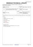
Corrections to Manual regarding the USB 2.0 Function
Module (USBa) in the RX630 Group
Information
Technical Notification
Category
TN-RX*-A115A/E
Rev. 1.00
Lot No.
Applicable
RX630 Group
Product
All
Reference
Document
RX630 Group User’s Manual:
Hardware Rev.1.60
(R01UH0040EJ0160)
This document describes corrections to section 31, USB 2.0 Function Module (USBa) in RX630 Group User's Manual:
Hardware.
•Overall
The following function name is corrected:
Before correction
SOF interpolation function
After correction
SOF recovery function
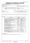
•Page 963 of 1681
Note 1 is added to Table 31.1 as follows:
Item
Features
Specifications
•
•
•
•
•
•
•
•
•
USB Device Controller (UDC) and transceiver for USB 2.0 are incorporated.
One port is provided.
Self-power mode or bus-power mode can be selected.
Programmable intervals for isochronous and interrupt transfers
Full-speed transfer (12 Mbps) is supported. *1
Control transfer stage control function
Device state control function
Auto response function for SET_ADDRESS request
SOF recovery function
Note 1. Low-speed transfer (1.5 Mbps) is not supported.
©2013. Renesas Electronics Corporation, All rights reserved.
Page 1 of 14
RENESAS TECHNICAL UPDATE
Date: Dec. 12, 2014
TN-RX*-A1A/E
•Page 967 of 1681
The description column for DVSTCTR0.RHST[2:0] bits in 31.2.3 is corrected as follows:
Before correction
Bit
Symbol
Bit Name
Description
b2 to b0
RHST[2:0]
USB Bus Reset Status
b2 b1 b0
0 0 0: Communication speed not determined
1 0 0: USB bus reset in progress
0 1 0: Full-speed connection
After correction
Bit
Symbol
Bit Name
Description
b2 to b0
RHST[2:0]
USB Bus Reset Status
b2 b1 b0
0 0 0: Communication speed not determined
0 1 0: USB bus reset in progress or full-speed connection
•Page 967 of 1681
The following note for the DVSTCTR0.WKUP bit in 31.2.3 is deleted:
Note 1. Only 1 can be written.
Page 2 of 14
TN-RX*-A1A/E'ate: Dec. 12, 2014
RENESAS TECHNICAL UPDATE
• Pages 968, 969 of 1681
The descriptions for registers CFIFO, D0FIFO, D1FIFO in 31.2.4 are corrected as follows:
Before correction
Address(es): USB0.CFIFO 000A 0014h, USB0.D0FIFO 000A 0018h, USB0.D1FIFO 000A 001Ch
b15
b14
b13
b12
b11
b10
b9
b8
b7
b6
b5
b4
b3
b2
b1
b0
0
0
0
0
0
0
0
FIFOPORT[15:0]
Value after reset:
0
0
0
0
0
0
0
0
0
Bit
Symbol
Bit Name
Description
R/W
b15 to b0
FIFOPORT[15:0]
FIFO Port
The valid bits in a FIFO port register depend on the settings of the
corresponding MBW and BIGEND bits as listed in Table 31.4 and
Table 31.5
R/W
FIFOPORT[15:0] Bits (FIFO Port)
Accessing the FIFOPORT[15:0] bits allows reading the received data from the FIFO buffer or writing the transmit data
to the FIFO buffer.
Each FIFO port register can be accessed only while the FRDY bit in each port control register (CFIFOCTR,
D0FIFOCTR, or D1FIFOCTR) is 1.
The valid bits in a FIFO port register depend on the settings of the corresponding MBW and BIGEND bits of port select
register (CFIFOSEL, D0FIFOSEL, or D1FIFOSEL), as listed in Table 31.4 and Table 31.5.
Table 31.4 Endian Operation in 16-Bit Access
CFIFOSEL.BIGEND Bit
D0FIFOSEL.BIGEND Bit
D1FIFOSEL.BIGEND Bit
0
1
Bits 15 to 8
N + 1 data
N + 0 data
Bits 7 to 0
N + 0 data
N + 1 data
Table 31.5 Endian Operation in 8-Bit Access
CFIFOSEL.BIGEND Bit
D0FIFOSEL.BIGEND Bit
D1FIFOSEL.BIGEND Bit
0
1
Bits 15 to 8
Access prohibited *1
Access prohibited *1
Bits 7 to 0
N + 0 data
N + 0 data
Note 1. Accessing an access-prohibited area is not allowed.
Page 3 of 14
TN-RX*-A1A/E'ate: Dec. 12, 2014
RENESAS TECHNICAL UPDATE
After correction
(1) When the MBW bit is 1
Address(es): USB0.CFIFO 000A 0014h, USB0.D0FIFO 000A 0018h, USB0.D1FIFO 000A 001Ch
Value after reset:
b15
b14
b13
b12
b11
b10
b9
b8
b7
b6
b5
b4
b3
b2
b1
b0
0
0
0
0
0
0
0
0
0
0
0
0
0
0
0
0
Bit
Symbol
Bit Name
Description
R/W
b15 to b0
—
FIFO Port
This port is used for reading receive data from the FIFO buffer and
writing transmit data to the FIFO buffer.
R/W
(2) When the MBW bit is 0
Address(es): USB0.CFIFO 000A 0014h, USB0.D0FIFO 000A 0018h, USB0.D1FIFO 000A 001Ch
b7
b6
b5
b4
b3
b2
b1
b0
0
0
0
0
L[7:0]
0
Value after reset:
Bit
Symbol
Bit Name
b7 to b0
L[7:0]
FIFO Port
0
0
0
Description
R/W
This port is used for reading receive data from the FIFO buffer and
writing transmit data to the FIFO buffer.
R/W
FIFO Port Bits
Accessing the FIFO port bits allows reading the received data from the FIFO buffer or writing the transmit data to the
FIFO buffer.
Each FIFO port register can be accessed only while the FRDY bit in each FIFO port control register (CFIFOCTR,
D0FIFOCTR, or D1FIFOCTR) is 1.
The valid bits in a FIFO port register depend on the settings of the corresponding MBW bit of the FIFO port select
register (CFIFOSEL, D0FIFOSEL, or D1FIFOSEL).
When the MBW bit is 1 (16-bit width), the data arrangement may differ from the data arrangement on the RAM
depending on the value of the MDEB.MDE[2:0] bits or the MDES.MDE[2:0] bits and the setting of the BIGEND bit
(CFIFOSEL.BIGEND, D0FIFOSEL.BIGEND, or D1FIFOSEL.BIGEND). Table 31.4 lists the endian operation in
16-bit access. Note that if the total number of transmit data bytes is odd, access the L[7:0] bits in bytes when writing the
last data.
When the MBW bit is 0 (8-bit width), access the L[7:0] bits in bytes.
Table 31.4 Endian Operation in 16-Bit Access
MDEB.MDE[2:0] bits
MDES.MDE[2:0] bits
000b (big endian)
111b (little endian)
CFIFOSEL.BIGEND Bit
D0FIFOSEL.BIGEND Bit
D1FIFOSEL.BIGEND Bit
0 (little endian)
1 (big endian)
0 (little endian)
1 (big endian)
Bits 15 to 8
Data in address N + 1
Data in address N
Data in address N + 1
Data in address N
Bits 7 to 0
Data in address N
Data in address N + 1
Data in address N
Data in address N + 1
Remarks
Bytes reversed
Bytes reversed
Page 4 of 14
TN-RX*-A1A/EDate: Dec 12, 2014
RENESAS TECHNICAL UPDATE
•Page 974 of 1681
The note for the BCLR bit in registers CFIFOCTR, D0FIFOCTR, and D1FIFOCTR in 31.2.6 is corrected as follows:
Before correction
Note 1. Only 0 can be read and 1 can be written.
After correction
Note 1. This bit is read as 0.
•Page 974 of 1681
The following note for the BVAL bit in registers CFIFOCTR, D0FIFOCTR, and D1FIFOCTR in 31.2.6 is deleted:
Note 2. Only 1 can be written.
•Page 981 of 1681
The notes for the value after reset of the INTSTS0 register in 31.2.12 are corrected as follows:
Before correction
b15
b14
VBINT RESM
Value after reset:
0
0
b13
b12
b11
b10
b9
SOFR
DVST
CTRT
BEMP
NRDY
0
0/1
*1
0
0
0
b8
b7
b6
BRDY VBSTS
0
0
*3
b5
b4
DVSQ[2:0]
0
0
b3
b2
VALID
0/1
*2
b1
b0
CTSQ[2:0]
0
0
0
0
b3
b2
b1
b0
Note 1. This bit is initialized to 0b by a power-on reset and 1b by a USB bus reset.
Note 2. These bits are initialized to 000b by a power-on reset and 001b by a USB bus reset.
Note 3. This bit is 1 when the USB0_VBUS pin input is high and 0 when the input is low.
After correction
b15
b14
VBINT RESM
Value after reset:
0
0
b13
b12
b11
b10
b9
SOFR
DVST
CTRT
BEMP
NRDY
0
0/1
*1
0
0
0
b8
b7
b6
BRDY VBSTS
0
0
*2
b5
b4
DVSQ[2:0]
0
*3
0
*3
VALID
0/1
*3
0
CTSQ[2:0]
0
0
0
Note 1. The value is 0 after the MCU is reset, and the value is 1 after a USB bus reset.
Note 2. The value is 1 when the USB0_VBUS pin is high, and the value is 0 when the USB0_VBUS pin is low.
Note 3. The value is 000b after the MCU is reset, and the value is 001b after a USB bus reset.
•Page 986 of 1681
The note for bits CRCE and OVRN of the FRMNUM register in 31.2.16 is corrected as follows:
Before correction
Note 1. Only 0 can be written.
After correction
Note 1: When setting each status to 0, write 0 to the bit that is cleared, and write 1 to the other bit.
Page 5 of 14
RENESAS TECHNICAL UPDATE
TN-RX*-A1A/EDate: Dec. 12, 2014
•Page 986 of 1681
The descriptions for the CRCE bit in 31.2.16 is corrected as follows:
Before correction
On detecting a CRC error, the USB module does not generate the internal NRDY interrupt request.
After correction
The USB module generates an internal NRDY interrupt request when a CRC error is detected.
•Page 991 of 1681
The note for bits SQSET and SQCLR of the DCPCTR register in 31.2.24 is corrected as follows:
Before correction
Note 1. This bit is read as 0. Only 1 can be written.
After correction
Note 1. This bit is read as 0.
•Page 996 of 1681
Descriptions for the PIPEMAXP.MXPS[8:0] bits in 31.2.27 are corrected as follows:
Before correction
Specifies the maximum data payload (maximum packet size) for the selected pipe.
These bits should be set to the appropriate value for each transfer type based on USB Specifications. While
MXPS[8:0] = 0, do not write to the FIFO buffer or set PID to BUF.
After correction
Specifies the maximum data payload (maximum packet size) for the selected pipe.
These bits should be set to the appropriate value for each transfer type based on USB Specifications 2.0. Note that the
maximum value for PIPE1 and PIPE2 is 256. While the MXPS[8:0] bits are 000h, do not write to the FIFO buffer or do
not set the PID[1:0] bits to 01b (BUF).
•Pages 998, 1002 of 1681
The note for bits SQSET and SQCLR of the PIPEnCTR register in 31.2.29 is corrected as follows:
Before correction
Note 1. Only 0 can be read and 1 can be written.
After correction
Note 1. This bit is read as 0.
Page 6 of 14
RENESAS TECHNICAL UPDATE
TN-RX*-A1A/EDate: Dec. 12, 2014
•Page 1017 of 1681
Figure 31.8 is corrected as follows:
Before correction
(1) Example of zero-length packet reception or data packet reception when BFRE = 0 (single-buffer mode)
*1
USB bus
Token Packet
Data Packet
ACK Handshake
FIFO buffer status
BRDY interrupt
(change in corresponding
bit in PIPEBRDY)
Ready for reception
Ready for read access
A BRDY interrupt is generated because the
2
buffer becomes ready for read access.*
(2) Example of data packet reception when BFRE = 1 (single-buffer mode)
*1
USB bus
FIFO buffer status
Token Packet
<Last> Data Packet
ACK Handshake
Ready for reception
Ready for read access
BRDY interrupt
(change in corresponding
bit in PIPEBRDY)
The buffer becomes
ready for read access.*2
A BRDY interrupt is generated
3
because the transfer has ended.*
(3) Example of packet transmission (single-buffer mode)
*1
USB bus
FIFO buffer status
Token Packet
Data Packet
Ready for transmission
ACK Handshake
Ready for write access
BRDY interrupt
(change in corresponding
bit in PIPEBRDY)
A BRDY interrupt is generated
because the buffer becomes
ready for write access.
Packet transmitted by host device
Packet transmitted by peripheral device
Note 1. The ACK handshake is not used in isochronous transfers.
Note 2. The FIFO buffer becomes ready for read access under the following condition:
When a packet is received while no data remains unread in the buffer in the CPU.
Note 3. A transfer ends under either of the following conditions:
(1) When a short packet including a zero-length packet is received
(2) When the number of packets specified in the transaction counter are received
Figure 31.8 Timing of BRDY Interrupt Generation
Page 7 of 14
RENESAS TECHNICAL UPDATE
TN-RX*-A1A/EDate: Dec. 12, 2014
After correction
(1) Example of zero-length packet reception or data packet reception when BFRE = 0 (single-buffer mode)
1
USB bus
Token Packet
FIFO buffer status
Data Packet
ACK Handshake
*
Ready for reception
Ready for read access
BRDY interrupt
(BRDYSTS.PIPEnBRDY
bit)
A BRDY interrupt occurs because the FIFO
2
buffer becomes ready for read access.*
(2) Example of data packet reception when BFRE = 1 (single-buffer mode)
1
USB bus
Token Packet
FIFO buffer status
<Last> Data Packet
ACK Handshake
*
Ready for reception
Ready for read access
BRDY interrupt
(BRDYSTS.PIPEnBRDY
bit)
The FIFO buffer becomes
ready for read access.*2
A BRDY interrupt occurs because
3
the transfer has ended.*
(3) Example of packet transmission (single-buffer mode)
1
USB bus
Token Packet
FIFO buffer status
Data Packet
ACK Handshake
Ready for transmission
*
Ready for write access
BRDY interrupt
(BRDYSTS.PIPEnBRDY
bit)
A BRDY interrupt occurs because the FIFO
buffer becomes ready for write access.
Packet transmitted by host device
Packet transmitted by function device
Note 1. The ACK handshake is not used in isochronous transfers.
Note 2. The FIFO buffer becomes ready for read access under the following condition:
When a packet is received while no data remains unread in the FIFO buffer on the CPU side.
Note 3. A transfer ends under either of the following conditions:
(1) When a short packet including a zero-length packet is received
(2) When the number of packets specified in the transaction counter are received
Figure 31.8 Timing of BRDY Interrupt Generation
Page 8 of 14
TN-RX*-A1A/EDate: Dec. 12, 2014
RENESAS TECHNICAL UPDATE
•Page 1019 of 1681
Figure 31.9 is corrected as follows:
Before correction
(1) Example of data transmission (single-buffer mode)
USB bus
Buffer status
NRDY interrupt
(change in corresponding
bit in PIPENRDY)*2
IN Token Packet
NAK Handshake
*1
Ready for write access (there is no data to be transmitted)
(2) Example of data reception: OUT token reception (single-buffer mode)
USB bus
Buffer status
OUT Token Packet
Data Packet
NAK Handshake
*1
Ready for read access (there is no space to receive data)
NRDY interrupt
(change in corresponding
bit in PIPENRDY)*2
(CRC bit, etc.)*3
(3) Example of data reception: PING token reception (single-buffer mode)
USB bus
Buffer status
PING Packet
NAK Handshake
Ready for read access (there is no space to receive data)
NRDY interrupt
(change in corresponding
bit in PIPENRDY)*2
Packet transmitted by host device
Packet transmitted by peripheral device
Note 1. The handshake is not used in isochronous transfers.
Note 2. The PIPENRDY bit is set to 1 only while the PID bits for the target pipe are set to 1.
Note 3. The CRC and OVRN bits change only while the target pipe is set to isochronous transfers.
Figure 31.9 Timing of NRDY Interrupt Generation
Page 9 of 14
RENESAS TECHNICAL UPDATE
Date: Dec. 12, 2014
TN-RX*-A1A/E
After correction
(1) Example of data transmission (single-buffer mode)
USB bus
FIFO buffer status
IN Token Packet
NAK Handshake
*1
Ready for write access (there is no data to be transmitted)
NRDY interrupt
(NRDYSTS.PIPEnNRDY
bit) *2
An NRDY interrupt occurs
(2) Example of data reception: OUT token reception (single-buffer mode)
USB bus
FIFO buffer status
OUT Token Packet
Data Packet
NAK Handshake
*1
Ready for read access (there is no space to receive data)
NRDY interrupt
(NRDYSTS.PIPEnNRDY
bit) *2
(CRCE bit, etc.) *3
An NRDY interrupt occurs
(3) Example of data reception: PING token reception (single-buffer mode)
USB bus
FIFO buffer status
PING Packet
NAK Handshake
Ready for read access (there is no space to receive data)
NRDY interrupt
(NRDYSTS.PIPEnNRDY
bit) *2
An NRDY interrupt occurs
Packet transmitted by the host device
Packet transmitted by the function device
Note 1. The handshake is not used in isochronous transfers.
Note 2. The PIPEnNRDY bit is set to 1 only while the PIPEnCTR.PID[1:0] bits are set to 01b (BUF response).
Note 3. The CRCE and the OVRN bits change only while the target pipe is set to isochronous transfers.
Figure 31.9 Timing of NRDY Interrupt Generation
Page 10 of 14
RENESAS TECHNICAL UPDATE
Date: Dec. 12, 2014
TN-RX*-A115A/E
•Page 1021 of 1681
Figure 31.10 is corrected as follows:
Before correction
(1) Example of data transmission
USB bus
IN Token Packet
Buffer status
Data Packet
ACK Handshake
*1
Ready for write access
(there is no data to be
transmitted)
Ready for transmission
BEMP interrupt
(change in corresponding
bit in PIPEBEMP)
(2) Example of data reception
USB bus
Data Packet (Maximum
Packet size over)
OUT Token Packet
STALL Handshake
BEMP interrupt
(change in corresponding
bit in PIPEBEMP)
Packet transmitted by host device
Packet transmitted by peripheral device
Note 1. The handshake is not used in isochronous transfers.
Figure 31.10 Timing of BEMP Interrupt Generation
After correction
(1) Example of data transmission
*1
USB bus
FIFO buffer status
IN Token Packet
Data Packet
ACK Handshake
Ready for write access
(there is no data to be
transmitted)
Ready for transmission
BEMP interrupt
(BEMPSTS.PIPEnBEMP
bit)
A BEMP interrupt occurs
(2) Example of data reception
USB bus
Data Packet (Maximum
packet size over)
OUT Token Packet
STALL Handshake
BEMP interrupt
(BEMPSTS.PIPEnBEMP
bit)
A BEMP interrupt occurs
Packet transmitted by the host device
Packet transmitted by the function device
Note 1. The handshake is not used in isochronous transfers.
Figure 31.10 Timing of BEMP Interrupt Generation
Page 11 of 14
RENESAS TECHNICAL UPDATE
TN-RX*-A115A/E
Date: Dec. 12, 2014
•Page 1032 of 1681
The descriptions for (4) Control Transfer Auto Response Function in 31.3.6.1 are corrected as follows:
Before correction
(4)
Control Transfer Auto Response Function
The USB module automatically responds to a correct SET_ADDRESS request. If any of the following errors occurs in
the SET_ADDRESS request, a response from the software is necessary.
•
•
•
•
•
Any transfer other than a control read transfer: bmRequestType ≠ 00h
Request error : wIndex ≠ 00h
Any transfer other than a no-data control transfer: wLength ≠ 00h
Request error: wValue > 7Fh
Control transfer of a device state error: INTSTS0.DVSQ[2:0] = 011b (Configured)
For all requests other than the SET_ADDRESS request, a response is required from the corresponding software.
After correction
(4)
Control Transfer Auto Response Function
The USB module automatically responds to a correct SET_ADDRESS request. If any of the following errors occurs in
the SET_ADDRESS request, a response from the software is necessary.
•
•
•
•
•
bmRequestType is not 00h: Any transfer other than a control write transfer
wIndex is not 00h: Request error
wLength is not 00h: Any transfer other than a no-data control transfer
wValue is larger than 7Fh: Request error
The INTSTS0.DVSQ[2:0] bits are 011b (configured state): Control transfer of a device state error
For all requests other than the SET_ADDRESS request, a response is required from the corresponding software.
•Page 1035 of 1681
The descriptions for (1) Counter Initialization in 31.3.9.3 are corrected as follows:
Before correction
(1)
Counter Initialization
The USB module initializes the interval counter under the following conditions.
• Power-on Reset
The PIPEPERI.IITV[2:0] bits are initialized.
• Buffer memory initialization using the ACLRM bit
The PIPEPERI.IITV[2:0] bits are not initialized but the count value is initialized. Setting the PIPEnCTR.ACLRM
bit to 0 starts counting from the value set in the PIPEPERI.IITV[2:0] bits.
After correction
(1)
Counter Initialization
The interval counter is initialized when the MCU is reset or when the PIPEnCTR.ACLRM bit is set to 1. The
PIPEPERI.IITV[2:0] bits are not initialized when the interval counter is initialized by using the ACLRM bit.
Page 12 of 14
RENESAS TECHNICAL UPDATE
Date: Dec. 12, 2014
TN-RX*-A115A/E
•Page 1036 of 1681
The descriptions for “When IITV = 0” in 31.3.9.3 (2) and Figure 31.13 are corrected as follows:
Before correction
• When IITV = 0: The interval counting starts at the frame following the frame in which software has set the PID[1:0]
PID bit setting
Token
NAK
Token
reception
is not waited
DATA
SOF
BUF
Token
reception
is waited
OUT
DATA
SOF
BUF
Token
reception
is not waited
OUT
SOF
USB bus
SOF
bits for the selected pipe to BUF.
BUF
Token
reception
is waited
Interval counter started
Figure 31.13 Relationship between Frames and Expected Token Reception when IITV = 0
After correction
• When IITV = 0
PID bit setting
Token
NAK
Token
reception
is not waited
DATA
SOF
OUT
DATA
SOF
OUT
SOF
USB bus
SOF
The interval counter starts when software has set the PID[1:0] bits for the selected pipe to BUF.
NAK
BUF
BUF
Token
reception
is not waited
Token
reception
is waited
Token
reception
is waited
Interval counter started
Figure 31.13 Relationship between Frames and Expected Token Reception when IITV = 0
Page 13 of 14
RENESAS TECHNICAL UPDATE
TN-RX*-A115A/E
Date: Dec. 12, 2014
•Page 1040 of 1681
The descriptions for SOF Interpolation Function in 31.3.10 are corrected as follows:
Before correction
31.3.10
SOF Interpolation Function
If data could not be received at intervals of 1 ms because an SOF packet was corrupted or missing, the USB module
interpolates the SOF. The SOF interpolation operation begins when the USBE and SCKE bits in SYSCFG have been set
to 1 and an SOF packet is received. The interpolation function is initialized under the following conditions.
• Power-on reset
• USB bus reset
• Suspended state detected
The SOF interpolation operates as follows.
• The interpolation function is not activated until an SOF packet is received.
• After the first SOF packet is received, interpolation is carried out by counting 1 ms with an internal clock of 48
MHz.
• After the second and subsequent SOF packets are received, interpolation is carried out at the previous reception
interval.
• Interpolation is not carried out in the suspended state or while a USB bus reset is being received.
The USB module supports the following functions based on the SOF packet reception. These functions also operate
normally with SOF interpolation, if the SOF packet was missing.
• Updating of the frame number
• SOFR interrupt timing
• Isochronous transfer interval count
If an SOF packet is missing when full-speed operation is being used, the FRMNUM.FRNM[10:0] bits are not updated.
After correction
31.3.10
SOF Recovery Function
If data could not be received at intervals of 1 ms because an SOF packet was corrupted or missing, the USB module
recovers the SOF. The SOF recovery operation begins when the USBE and SCKE bits in SYSCFG have been set to 1 and
an SOF packet is received. The recovery function is initialized under the following conditions.
• MCU reset
• USB bus reset
• Suspended state detected
The SOF recovery operates as follows.
•
•
•
•
The recovery function is not activated until an SOF packet is received.
After the first SOF packet is received, recovery is carried out by counting 1 ms with an internal clock of 48 MHz.
After the second and subsequent SOF packets are received, recovery is carried out at the previous reception interval.
Recovery is not carried out in the suspended state or while a USB bus reset is being received.
The USB module supports the following functions based on the SOF packet reception. These functions also operate
normally with SOF recovery, if the SOF packet was missing.
• Updating of the frame number
• SOFR interrupt timing
• Isochronous transfer interval count
If an SOF packet is missing when full-speed operation is being used, the FRMNUM.FRNM[10:0] bits are not updated.
Page 14 of 14