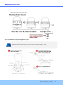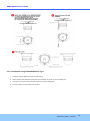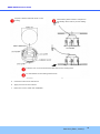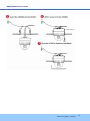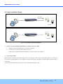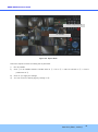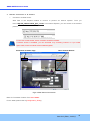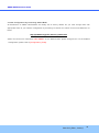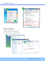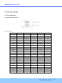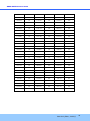
1
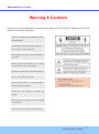
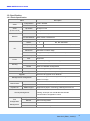
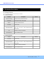
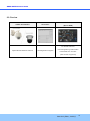
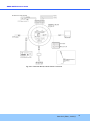
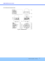
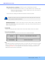
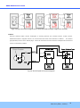
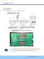
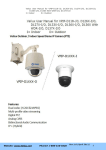
ONSIP OPTZ O/I Users’ Guide ONSIP OPTZ36XO ONSIP OPTZ36XI Rev.1.0 (Nov., 2011) 1 ONSIP OPTZ O/I Users’ Guide Revision History Date Rev No. 2011-11-01 1.0 Description First manual revision creation. Rev.1.0 (Nov., 2011) 2 ONSIP OPTZ O/I Users’ Guide Warning & Cautions If you fail to read this information and handle the product incorrectly, faulty or malfunction as well as death or serious injury may occur. This Unit should be installed by train ed personnel. Immediately stop using when the product emits smoke or abnormal heat. Never install the product in area exposed to oil or gas. Never install the product on a ceiling that cannot hold its weight. Never touch the power cord with wet hands. Clean only with dry cloth. Never use the product in extremely high or low temperature condition. Never drop, hit, strongly nor vibrate the product. Never expose the product to direct sunlight or severe ray. Never touch the front glass of the product. Rev.1.0 (Nov., 2011) 3 ONSIP OPTZ O/I Users’ Guide Indications: Warning: Death or Serious Injury will occur without following Warning. Caution : Operational Problem(Faulty & Malfunction) will occur without complying with Caution Reference : Technical Information for Users Rev.1.0 (Nov., 2011) 4 ONSIP OPTZ O/I Users’ Guide Table of Contents Table of Contents ................................................................................ 5 1. Introduction ................................................................................... 7 1.1. Overview of ONSIP OPTZ36XO/I ................................................................... 7 1.2. Specification ........................................................................................... 8 1.2.1. Basic Specification 1.2.2. Detailed Specification of Camera Module & PTZ오류! 책갈피가 정의되어 있지 않습니다. 1.2.3. Basic Specification오류! 책갈피가 정의되어 있지 않습니다. 1.2.4. Detailed Specification of Camera Module오류! 책갈피가 정의되어 있지 않습니다. 1.3. Application of ONSIP OPTZ36XO/I ................................................................. 9 2. Production Description................................................................... 10 2.1. Package Contents .................................................................................... 10 2.1.1. ONSIP OPTZ36XO....................................................................................................................... 10 2.1.2. ONSIP OPTZ36XI ........................................................................................................................ 10 2.2. Preview .................................................................................................. 11 2.3. Physical Description .................................................................................. 12 2.3.1. External View ................................................................................................................................ 12 2.3.2. Bottom View & Connection Diagram ............................................................................................ 12 2.3.3. External & Internal View ............................................................................................................... 14 2.4. Functional Description ............................................................................... 16 3. Bracket Installation ...................................................................... 19 3.1. ONSIP OPTZ36XO ................................................................................... 19 3.1.1. Basic Components & Mounting Accessories ................................................................................ 19 3.1.2. Preparation ................................................................................................................................... 19 3.1.3. Installation using Walling Mount Type .......................................................................................... 21 3.2 ONSIP OPTZ36XI...................................................................................... 23 3.2.1. Preparation ................................................................................................................................... 23 3.2.2. Installation using Ceiling Mount Type ........................................................................................... 24 3.2.3. Installation using Embedded Mount Type .................................................................................... 25 Rev.1.0 (Nov., 2011) 5 ONSIP OPTZ O/I Users’ Guide 4. Installation .................................................................................. 28 4.1. Required System Specification .................................................................... 28 4.2. Quick Installation Guide ............................................................................. 29 5. Trouble Shooting .......................................................................... 35 5.1. No Video on Viewer................................................................................... 35 5.2. Windows vista and Windows 7 User for Record & Capture Problem ................... 36 5.3 Technical Inquiry........................................................................................ 39 6. Appendix .................................................................................... 40 6.1. FAN & Heater .......................................................................................... 40 6.2. DIP Switch Setting .................................................................................... 42 Rev.1.0 (Nov., 2011) 6 ONSIP OPTZ O/I Users’ Guide 1. Introduction 1.1. Overview of ONSIP OPTZ36XO/I ONSIP OPTZ36XO/I, as a state-of-the-art 1Channel Speed Dome Network Camera based on integrated Embedded Software technologies such as H.264 & MJPEG, G.726 & PCM Video & Audio Compression, Embedded Web Server, Embedded Streaming Server, various Network Protocols, transmits synchronized video and audio data in real time through IP Network as well as supports bi-directional audio communication by allowing transmission of audio from Client PC to ONSIP OPTZ36XO/I. ONSIP OPTZ36XO/I, with completed Integration with analog CCTV camera, Digital and network technology, is applicable for various sectors such as Security, Remote Monitoring, Remote Education, Simple Video Conference as well as Internet Broadcasting System etc. Rev.1.0 (Nov., 2011) 7 ONSIP OPTZ O/I Users’ Guide 1.2. Specification 1.2.1. Basic Specification Class Description Compression H.264 / MJPEG Video Resolution **Refer to the datasheet Audio Up Stream 32 Kbps G.726 (Bi-directional) Down Stream 64 Kbps PCM Interface Network Access Network Protocol RJ-45, 10/100 Mbps Static, DHCP, PPP/PPPoE IPv4/6, TCP, UDP, IGMP, ICMP, ICMPv6 etc. Sensor 4 NC, NO Selectable Relay Output 2 Alarm or Remote ON/OFF Control (30V, 1A) RS-232C Factory Default I/O Mic/Line In Line Out Selectable on Admin Page 1 V p-p Audio Output for Amp embedded Speaker CVBS Output Supported PoE Supported Power AC In Water-Proof 12VDC Adaptor (higher than 2 Amp) IP66 Housing Heater Refer to Installation Configuration Installation Type Bracket Wall, Ceiling, Ceiling Embedded Type Motion Detection 3 Regions Upgrade Optional Shape & Sensitivity for 3 Regions Remote F/W Upgrade via IP Network Management & Configuration Remote Management & Configuration using IP Network and Admin Tool Page Web Viewer Simple Access via Internet explorer Speco-NVR CMS Software Client/Viewer Dynamic IP DDNS support Supported by Speco Technology’s Management Server 802.1x authentication, User ID & Password Protection, IP Security Management Filtering, Audio per user and Bi-directional audio communication configuration control Sync to PC Time Sync to PC Time Manual Manual Configuration Internet Time Server Sync to Time Server Configuration Management DLS Summer Time Configuration Rev.1.0 (Nov., 2011) 8 ONSIP OPTZ O/I Users’ Guide 1.3. Application of ONSIP OPTZ36XO/I - Security Surveillance (Building, Stores, Manufacturing Device, Parking Lot, Bank, Public Office & Military etc) - Remote Monitoring (Hospital, Kindergarten, Traffic Status, Public Area) - Video Conference, Remote Lecture, Internet Broadcasting - Climate & Environment Surveillance Rev.1.0 (Nov., 2011) 9 ONSIP OPTZ O/I Users’ Guide 2. Production Description 2.1. Package Contents Open the package and check if the followings are included; 2.1.1. ONSIP OPTZ36XO Contents Bracket & Housing Accessories Manual IP Camera Description Remark Outdoor Housing, Wall Mount Bracket Screw (M4x15 4EA), Safety Cable Housing Installation Manual Camera body Wrench, Safety Cable, Cable Tie, Terminal Block Tools & Accessories (2Pin, 3Pin , 5Pin ,6Pin : 1EA), Screw(Ø 3x6 2EA, Ø 4x16 5EA) CD Quick Reference Software & Product User Manual Quick Installation Guide 2.1.2. ONSIP OPTZ36XI Content IP Camera Description Remark Camera body Wrench, Safety Cable, Cable Tie, Terminal Block Tools & Accessories (2Pin, 3Pin , 5Pin ,6Pin : 1EA), Screw(Ø 3x6 2EA, Ø 4x16 5EA) CD Quick Reference Software & Product User Manual Quick Installation Guide Rev.1.0 (Nov., 2011) 10 ONSIP OPTZ O/I Users’ Guide 2.2. Preview ONSIP OPTZ36XO/I IP-Installer CMS Software (Speco-NVR) PC based Client for Speed Dome Network Camera IP Assignment Program monitoring/storing Video/Audio transmitted form Product (Max. 64CH supported) Rev.1.0 (Nov., 2011) 11 ONSIP OPTZ O/I Users’ Guide 2.3. Physical Description 2.3.1. External View Fig 2-1. External View of ONSIP OPTZ36XO/I 2.3.2. Bottom View & Connection Diagram 12VDC Fig 2-2-1. Terminal Block, LAN & Power Connector Rev.1.0 (Nov., 2011) 12 ONSIP OPTZ O/I Users’ Guide Fig 2-2-2. Terminal Block, LAN & Power Connector Rev.1.0 (Nov., 2011) 13 ONSIP OPTZ O/I Users’ Guide 2.3.3. External & Internal View Fig 2-3-1. Connector Part Rev.1.0 (Nov., 2011) 14 ONSIP OPTZ O/I Users’ Guide 1. Bubble 9. LAN (100 Base-T) 2. Lock Screw 10. RS-485 (D+, D-) 3. Camera 11. Power Input (DC12V) 4. Dip Switch1 12. Aux 5. Dip Switch2 13. Video out (Analog CVBS) 6. Lock Holder 14. Power LED 7. Alarm 15. Mic / Line In 8. Line Out 16. Fan / Heater Fig 2-3-2. Connector Part Rev.1.0 (Nov., 2011) 15 ONSIP OPTZ O/I Users’ Guide Fig 2-4. Outdoor Housing 2.4. Functional Description AC Power Connect 24 Volt AC adaptor to this terminal for supplying power to the network camera. DC Power Connect 12 Volt DC adaptor to this terminal for supplying power to the network camera. AC adapter which is compliant to the specification for ONSIP OPTZ36XO/I should be used. Misuse of power supply can cause damage to ONSIP OPTZ36XO/I. Speco assumes no responsibility for misuse of the power supply. MIC/LINE IN Connect external audio source or microphone. Line Out Connect speakers with built in amplifier. Audio from remote site is output through Line out in bi-directional audio mode. 100Base-T 100Mbps Ethernet connector (RJ-45). 2 LEDs on the Ethernet connector shows the status of ONSIP OPTZ36XO/I as the followings: Rev.1.0 (Nov., 2011) 16 ONSIP OPTZ O/I Users’ Guide - Status LED (Dual Color - Red/Green): It will be lit in green or red depending on the status. Green: Green color indicates that the camera is in normal operation mode. Continuous green indicates that data transmission is possible. Blinking green means that someone is connected to ONSIP OPTZ36XO/I. Red: Continuous or blinking red indicates that hardware is in abnormal condition. Red/Green LED will be lit with red momentarily and it will be lit with green after a while when power is applied into ONSIP OPTZ36XO/I. LINK/LAN LED (Orange): It will be lit with orange color when network cabling is all right. Blinking orange color indicates that normal data transmission is under way. Off state indicates that there is trouble in network connection. HEATER/FAN Used for connecting power cable of heater and fan. Power cable of heater and fan is in the bracket. Alarm In/Out (ALARM/AUX) Used for connecting alarm sensor, alarm annunciation device to ONSIP OPTZ36XO/I. Class Alarm IN Description Sensor In (+). NC/NO Selectable in Admin Mode Alarm IN GND Ground for Sensor In Aux OUT Alarm Output Terminal Aux OUT(GND) Ground for Sensor Output Aux Relay output is provided for connecting alarm devices or for remote on/off control of devices such as light. Relay is normal open and it will be closed upon alarm annunciation or remote on. The relay is capable of switching 30V AC/DC, 2A. For the application which needs power switching beyond this limit, use additional relay switch as shown as below figure. Rev.1.0 (Nov., 2011) 17 ONSIP OPTZ O/I Users’ Guide Fig 2-5. Relay Connection Diagram (Left: lower than 30V, 2A, Right: Higher than 30V 2A) Alarm Connect external alarm sensor. Examples of sensing devices are infrared sensor, motion sensor, heat/smoke sensor, magnetic sensor, etc. Connect the two wires of the sensors to “SNS In”. The sensor type (NC/NO) can be set in admin page. 10mA can be flown into sensor device. Multiple sensor devices can be connected in parallel. Photo Coupler NO/NCType Open CollectorType Sensor1+ Sensor Device Sensor Device Sensor1- +12V GND Sensor Power Supply Sensor Power Supply Fig 2-6. Sensor Input Connection Diagram Rev.1.0 (Nov., 2011) 18 ONSIP OPTZ O/I Users’ Guide 3. Bracket Installation 3.1. ONSIP OPTZ36XO 3.1.1. Basic Components & Mounting Accessories 3.1.2. Preparation 1. Open the Dome Cover by unscrewing with wrench. Rev.1.0 (Nov., 2011) 19 ONSIP OPTZ O/I Users’ Guide 2. Configure the DIP Switch by referring Appendix. - When using system controller for the control of the dome, always set the RS-485 communication channel to be: 2400 bps, 8 bit, 1 stop bit, no parity. 3. Place the Dome Cover and screw. Rev.1.0 (Nov., 2011) 20 ONSIP OPTZ O/I Users’ Guide 3.1.3. Installation using Walling Mount Type The wall should be strong enough to hold 4 times of the weight of the camera (5.3 KG). This means that the wall should withstand weight of 21.2 KGs in the minimum. 1. Pass the combined cable through the inside Cable Gland. CABLE GLAND COMBINED CABLE 2. Fix the end of Cable Gland on the bottom case and coat the attached line between top & bottom of Cable Gland bottom case with silicone. For the installation at Bottom of Bracket, Gland Cable Installation is not required (refer to the below Fig). Rev.1.0 (Nov., 2011) 21 ONSIP OPTZ O/I Users’ Guide Hidden Cable Exposed Cable 3. Connect Sun-Visor with Wall Mounting Bracket. (1) 4. After connecting Product and Cable, install the product by inserting Product into internal fixing hole of housing and turning in clockwise. (2) 5. Assemble the Bubble. (3) Rev.1.0 (Nov., 2011) 22 ONSIP OPTZ O/I Users’ Guide 3.2 ONSIP OPTZ36XI 3.2.1. Preparation 1. Open the Dome Cover by unscrewing with wrench. 2. Configure the DIP Switch by referring Appendix. - When using system controller for the control of the dome, always set the RS-485 communication channel to be: 2400 bps, 8 bit, 1 stop bit, no parity. Rev.1.0 (Nov., 2011) 23 ONSIP OPTZ O/I Users’ Guide 3. Place the Dome Cover and screw. 3.2.2. Installation using Ceiling Mount Type Ceiling board should be strong enough to hold the weight of approx.. 2Kg. Rev.1.0 (Nov., 2011) 24 ONSIP OPTZ O/I Users’ Guide 3.2.3. Installation using Embedded Mount Type 1. Prepare 190mm Diameter Hole on the ceiling. 2. Place Safety Wire between suspension and Safety Ire Hole to prevent falling-off. 3. Fold the Lock Lever and insert the bracket into the ceiling hole. 4. Fix the bracket to the ceiling with screws. Rev.1.0 (Nov., 2011) 25 ONSIP OPTZ O/I Users’ Guide Prepare 190mm Diameter Hole on the Ceiling. Place Safety Wire between suspension and Safety Wire Hole to prevent fallingoff. Fold the Lock Lever and insert the Bracket into the Ceiling Hole. Fix the Bracket to the Ceiling with Screws. 5. Insert the Camera into the Mount. 6. Apply screw to fix the Camera. 7. Place the cover to finish the installation. Rev.1.0 (Nov., 2011) 26 ONSIP OPTZ O/I Users’ Guide Rev.1.0 (Nov., 2011) 27 ONSIP OPTZ O/I Users’ Guide 4. Installation 4.1. Required System Specification Required Specification of PC for Camera Configuration & Control. Class Recommendation Remark CPU Pentium-4 3Ghz RAM 1GB Graphic Card Higher than ATI Chip-Set based 64M LAN Card Higher than 100Mbps OS Windows XP Web Browser Higher than Internet Explorer 6.0 1600x1200(UXGA) * * Operating Systems supported: Windows 2000 Professional, Windows XP / Vista / 7 Rev.1.0 (Nov., 2011) 28 ONSIP OPTZ O/I Users’ Guide 4.2. Quick Installation Guide AC Adaptor LAN Switch Product LAN Switch supporting IEEE802.3at PoE Product Fig 4-1. LAN Cable Connection Diagram 1. Connect PC and ONSIP OPTZ36XO/I to Network Device (HUB) I. Prepare a PC which needs to be connected to Network. II. Connect PC (or Lab-Top) with Product as Fig 4-1. Power will be applied to product separately via Power Device (AC Adaptor). 2. Install Speco-NVR Speco-NVR is a multi-channel CMS program for to IP camera or Video server. Install Speco-NVR on remote PC to connect to these products. It is needed to assign connection information to Speco-NVR program before connection. Insert the CD provided with product into the PC and install the Speco-NVR. Rev.1.0 (Nov., 2011) 29 ONSIP OPTZ O/I Users’ Guide Admin Page Button IP installer Figure 4-2. Speco-NVR Follow the sequence below for setting the IP parameter i) Run IP installer ii) Click ① in IP installer window.> Double click on ② > Fill in ④ > make a selection in ⑤ > Fill the parameters in ⑥ iii) Click on ⑨ to apply the settings. iv) You can connect to admin page by clicking on ⑩. Rev.1.0 (Nov., 2011) 30 ONSIP OPTZ O/I Users’ Guide 3 1 2 9 10 5 4 7 6 8 Click on the field in ③ for sorting and rearranging the list. Select network mode that best suits from the drop down list in ⑤. You can choose either Static or ADSL and Auto (DHCP), respectively. If ADSL and Auto are selected, the fields in ⑥ is deactivated. In case of ADSL, fill the User Name and Password in ⑧ with the values provided by your ISP. If DDNS service is needed, Check at the box and fill the empty field with hostname you want in ⑦. Rev.1.0 (Nov., 2011) 31 ONSIP OPTZ O/I Users’ Guide 3. Remote Connection to IP Camera I. Connection via Web Viewer Web View is the simplest method to connect to product via internet explorer. Once you insert ”http://IP_address:HTTP_port_number” into Internet Explorer, you can access to the relevant product. For the use of Web Viewer, Active-X module should be installed. If internet access is available, you can download it by accessing Camera or if you install Speco-NVR, Active-X module will be installed together. Connection to Admin Page Basic Control Buttons Video Crop Control Fig 4-3. Web Viewer Connection Basic ID / Password of Admin Tool: root / admin For the detail, please refer to [Configuration_Guide]. Rev.1.0 (Nov., 2011) 32 ONSIP OPTZ O/I Users’ Guide 1) Connection through Speco-NVR Click the camera assignment button for setting camera address. Input the description, address, Ch#, User ID, Password and port and then click the save button. After assignment procedure, you must click the SAVE button. You can see the live video when you click the live view button as below. When you exit Speco-NVR, you have to input the ID/PW, admin/1234. Details for the Speco-NVR can be found in [Speco-NVR User’s Guide]. Camera Assignment Live view Exit Program Default ID/PW: admin/1234 Camera Assignment Example Save Figure 4-4. Speco-NVR Rev.1.0 (Nov., 2011) 33 ONSIP OPTZ O/I Users’ Guide 4. Initial Configuration by connecting Admin Mode All Parameters of ONSIP OPTZ36XO/I are initially set as factory default. So you must change them with appropriate value to your network configuration by accessing via Admin Tool. Admin Tool Access Method is as below. Http://[IP Address]:[HTTP Port No.]/ admin.htm Admin Tool Access ID / Password: root / admin. As it is Default Value, please change them. For the detailed Configuration, please refer to [Configuration_Guide]. Rev.1.0 (Nov., 2011) 34 ONSIP OPTZ O/I Users’ Guide 5. Trouble Shooting 5.1. No Video on Viewer Network Connection Status Check(Ping Test) You can check the Network Connection Status by doing Ping Test. - Start > Run > cmd > Ping IP Address (EX>ping 172.16.42.51). - If you get the response such as “Reply from~”, Network Configuration & Connection Status is good. Please re-try to access or refer to other trouble shooting category. ( 1 ). - If you get the response such as “Request timed out”, Network Configuration & Connection Status is in problem. Please check the Network Cable and Configuration. ( 2 ) 1 2 Rev.1.0 (Nov., 2011) 35 ONSIP OPTZ O/I Users’ Guide 5.2. Windows vista and Windows 7 User for Record & Capture Problem For the use of Video Recording & Capture function on Speco-NVR and Web Viewer, Windows Vista and Windows 7 Users are required to configure “User Account Configuration” and “Program Execution Entitlement Configuration”. If not configure, Recorded File won’t be generated or Captured Image on Web Viewer won’t be saved. Windows Vista Configuration 1. User Account Configuration 1) Select “User Account” on Control Panel 2) Select “Turn User Account Control on or off” 3) Uncheck “Use User Account Control to help protect your computer”. 2. Program Execution Entitlement Configuration 1) Select “NVR” icon on the wallpaper. 2) Select “Properties” menu popped up by clicking right button on Mouse. 3) Select Check Box of “Run this program as an administrator” from the compatibility Tap. Rev.1.0 (Nov., 2011) 36 ONSIP OPTZ O/I Users’ Guide Windows 7 Configuration 1. User Account Configuration 1) Select “User Account” on Control Panel 2) Select “Change User Account Control Setting” 3) Set the Alarm Level at the lowest “Never Notify” Rev.1.0 (Nov., 2011) 37 ONSIP OPTZ O/I Users’ Guide 2. Program Execution Entitlement Configuration 1) Select “NVR” icon on the wallpaper 2) Select “Properties” menu popped up by clicking right button on Mouse 3) Select Check Box of “Run this program as an administrator” from the compatibility Tap. Rev.1.0 (Nov., 2011) 38 ONSIP OPTZ O/I Users’ Guide 5.3 Technical Inquiry Please contact to your supplier if you still have problem even taking all trouble shootings. For the quickest solution, please prepare all information below; 1. Product Model Name 2. Serial No. & Mac Address 3. Date of Purchase 4. Summary of Problem 5. Error Message Rev.1.0 (Nov., 2011) 39 ONSIP OPTZ O/I Users’ Guide 6. Appendix 6.1. FAN & Heater FAN & Heater is inside Housing of Outdoor Speed Dome. At ONSIP OPTZ36XO/I, FAN & Heater will operate. Cablings for the Fan & Heater are completed in the Factory At ONSIP OPTZ36XO/I, FAN & Heater will operate by connecting power cable of FAN & Heater to HEATER/FAN connector at bottom of product. . Detailed Specification Category Description Heater Control Temp. On: below 10℃, Off: over 15℃ FAN Control Temp. On: over 45℃, Off: below 35℃ Operational Temp. -40℃ ~ +60℃ Operational Humidity Below 90% Water-Proof IP 66 Materials Poly Carbonate (Bubble), Aluminum (Body) Appearance 253Ø (diameter) x 307mm(Height) x 190Ø (Bubble) Power Consumption 18W Max (With Camera: 43W Max) Rev.1.0 (Nov., 2011) 40 ONSIP OPTZ O/I Users’ Guide Weight 3.4kg (including Camera : 5.3kg) Rev.1.0 (Nov., 2011) 41 ONSIP OPTZ O/I Users’ Guide 6.2. DIP Switch Setting A. ID Configuration * Factory Default: Camera ID = 1 (1-ON, 0-OFF) DIP SW ID VALUE DIP SW ID VALUE DIP SW ID VALUE 10000000 1 00010100 40 11110010 79 01000000 2 10010100 41 00001010 80 11000000 3 01010100 42 10001010 81 00100000 4 11010100 43 01001010 82 10100000 5 00110100 44 11001010 83 01100000 6 10110100 45 00101010 84 11100000 7 01110100 46 10101010 85 00010000 8 11110100 47 01101010 86 10010000 9 00001100 48 11101010 87 01010000 10 10001100 49 00011010 88 11010000 11 01001100 50 10011010 89 00110000 12 11001100 51 01011010 90 10110000 13 00101100 52 11011010 91 01110000 14 10101100 53 00111010 92 11110000 15 01101100 54 10111010 93 00001000 16 11101100 55 01111010 94 10001000 17 00011100 56 11111010 95 01001000 18 10011100 57 00000110 96 11001000 19 01011100 58 10000110 97 00101000 20 11011100 59 01000110 98 10101000 21 00111100 60 11000110 99 Rev.1.0 (Nov., 2011) 42 ONSIP OPTZ O/I Users’ Guide 01101000 22 10111100 61 00100110 100 11101000 23 01111100 62 10100110 101 00011000 24 11111100 63 01100110 102 10011000 25 00000010 64 11100110 103 01011000 26 10000010 65 00010110 104 11011000 27 01000010 66 10010110 105 00111000 28 11000010 67 01010110 106 10111000 29 00100010 68 11010110 107 01111000 30 10100010 69 00110110 108 11111000 31 01100010 70 10110110 109 00000100 32 11100010 71 01110110 110 10000100 33 00010010 72 11110110 111 01000100 34 10010010 73 00001110 112 11000100 35 01010010 74 10001110 113 00100100 36 11010010 75 01001110 114 10100100 37 00110010 76 11001110 115 01100100 38 10110010 77 00101110 116 11100100 39 01110010 78 10101110 117 01101110 118 00100101 164 01001011 210 11101110 119 10100101 165 11001011 211 00011110 120 01100101 166 00101011 212 10011110 121 11100101 167 10101011 213 01011110 122 00010101 168 01101011 214 11011110 123 10010101 169 11101011 215 00111110 124 01010101 170 00011011 216 10111110 125 11010101 171 10011011 217 01111110 126 00110101 172 01011011 218 11111110 127 10110101 173 11011011 219 00000001 128 01110101 174 00111011 220 10000001 129 11110101 175 10111011 221 01000001 130 00001101 176 01111011 222 11000001 131 10001101 177 11111011 223 00100001 132 01001101 178 00000111 224 10100001 133 11001101 179 10000111 225 01100001 134 00101101 180 01000111 226 Rev.1.0 (Nov., 2011) 43 ONSIP OPTZ O/I Users’ Guide 11100001 135 10101101 181 11000111 227 00010001 136 01101101 182 00100111 228 10010001 137 11101101 183 10100111 229 01010001 138 00011101 184 01100111 230 11010001 139 10011101 185 11100111 231 00110001 140 01011101 186 00010111 232 10110001 141 11011101 187 10010111 233 01110001 142 00111101 188 01010111 234 11110001 143 10111101 189 11010111 235 00001001 144 01111101 190 00110111 236 10001001 145 11111101 191 10110111 237 01001001 146 00000011 192 01110111 238 11001001 147 10000011 193 11110111 239 00101001 148 01000011 194 00001111 240 10101001 149 11000011 195 10001111 241 01101001 150 00100011 196 01001111 242 11101001 151 10100011 197 11001111 243 00011001 152 01100011 198 00101111 244 10011001 153 11100011 199 10101111 245 01011001 154 00010011 200 01101111 246 11011001 155 10010011 201 11101111 247 00111001 156 01010011 202 00011111 248 10111001 157 11010011 203 10011111 249 01111001 158 00110011 204 01011111 250 11111001 159 10110011 205 11011111 251 00000101 160 01110011 206 00111111 252 10000101 161 11110011 207 10111111 253 01000101 162 00001011 208 01111111 254 11000101 163 10001011 209 11111111 255 Rev.1.0 (Nov., 2011) 44 ONSIP OPTZ O/I Users’ Guide B. PROTOCOL rd th Set by 3 ,4 Switch of DIP Switch 2. Factory Default: Pelco-D & Pelco-P (Auto) DIP SW2 - 3rd 4th OFF / OFF Pelco-D or Pelco-P ON / ON Maxpro protocol C. BAUD RATE SETTING th th Set by 7 ,8 Switch of DIP Switch 2. Changeable Speed: 4800bps, 9600bps Factory Default: 2400bps. th DIP SW2-7th DIP SW2-8th BAUD RATE OFF OFF Not Used OFF ON 2400bps ON OFF 4800bps ON ON 9600bps th * 5 , 6 Switch of DIP Switch 2 is not used. Rev.1.0 (Nov., 2011) 45