1
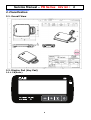
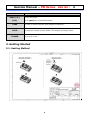
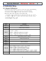
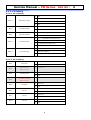
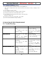
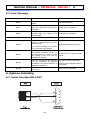
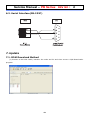
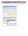
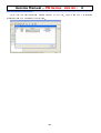
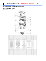
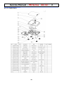
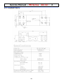
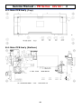
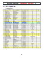
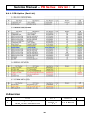
Service Manual – PB Series REV NO : 2
PB Series
Service Manual
LAST Rev. NO :
2
LAST Rev. Date : 2009. 06. 10
1
Service Manual – PB Series REV NO : 2
Table of Contents
1. Proper Operation / Introduction ........................................................................................................................ 3
1.1. Preface...................................................................................................................................................... 3
1.2. Precaution ................................................................................................................................................. 3
2. Classification ...................................................................................................................................................... 4
2.1. Overall View ............................................................................................................................................. 4
2.2. Display Pad (Key Pad) ............................................................................................................................. 4
2.2.1. PB(Basic) ........................................................................................................................................ 4
2.2.2. PB(Full Option) ..................................................................
오류!
오류! 책갈피가 정의되어 있지 않습니다.
않습니다.
3. Getting Started ................................................................................................................................................... 5
3.1. Sealing Method ......................................................................................................................................... 5
4. Calibration Mode ................................................................................................................................................ 6
4.1. General Calibration .................................................................................................................................. 6
4.1.1. C4 Setting ....................................................................................................................................... 7
4.1.1.1. C4-1 Setting ................................................................................................................................ 7
4.1.2. SPAN Calibration Setting (C-3) .................................................................................................... 8
4.1.3. Gravity Constant Value Setting (C-9) .......................................................................................... 8
4.1.4. Calibration factor Setting (C-10) .................................................................................................. 8
4.1.6. Percent Calibration (C-7) .............................................................................................................. 9
4.1.7. Battery Calibration (C-8) ............................................................................................................ 10
5. Servicing & Parts Replacement ...................................................................................................................... 10
5.1. Trouble Shooting .................................................................................................................................... 10
5.2. Error Message ........................................................................................................................................ 11
6. Options Installing .............................................................................................................................................. 11
6.1. Serial Interface(RS-232C) ..................................................................................................................... 11
7. Update ............................................................................................................................................................... 12
7.1. ROM Download Method ......................................................................................................................... 12
8. Exploded Views & Parts List .......................................................................................................................... 15
8.1. Exploded View ....................................................................................................................................... 15
8.2. Loadcell Ass’y ........................................................................................................................................ 17
8.3. Main PCB Ass’y (Top) ........................................................................................................................... 18
8.4. Main PCB Ass’y (Bottom) ...................................................................................................................... 18
8.5. Display Ass’y ...............................................................................
8.6. Scale Ass’y ..................................................................................
오류!
오류! 책갈피가 정의되어 있지 않습니다.
않습니다.
오류!
오류! 책갈피가 정의되어 있지 않습니다.
않습니다.
9.Revision ............................................................................................................................................................. 20
2
Service Manual – PB Series REV NO : 2
1. Proper Operation / Introduction
1.1. Preface
Thank you for purchasing of our CAS scale.
This scale has been designed with CAS reliability, under rigid quality control
and with outstanding performance.
WE hope that your departments enjoy with high quality of CAS product.
This manual will help you with proper operations and care of the PB(Portable Bench).
Please keep it handy for the future references.
1.2. Precaution
•
Make sure that you plug your scale into the proper power outlet.
•
Place the scale on a flat and stable surface.
•
Plug into a power outlet 30 minutes before operations.
•
Keep the scale away from strong EMI noises may cause incorrect weight readings.
•
This scale must be installed in a dry and liquid free environment.
•
Do not subject the scale to sudden temperature changes.
•
Do not subject the platter to sudden shocks.
•
If the scale is not properly level, please adjust the 4 legs at the bottom of the scale (turn
legs clockwise or counterclockwise) so as to center the bubble of the leveling gauge
inside the indicated circle.
3
Service Manual – PB Series REV NO : 2
2. Classification
2.1. Overall View
2.2. Display Pad (Key Pad)
2.2.1. PB(Basic)
4
Service Manual – PB Series REV NO : 2
Key
ZERO (-O-)
Function
To set zero point
[Set]
To do [SET] key in the SETUP mode.
TARE
To input or cancel the tare (the weight of container).
HOLD
To make the weight of item stable. This weight is average value.
POWER
To turn on or off.
3. Getting Started
3.1. Sealing Method
-
5
Service Manual – PB Series REV NO : 2
4. Calibration Mode
4.1. General Calibration
Pressing and holding calibration switch press [POWER] key to go to calibration mode.
User can move to other mode by using [ZERO] key in the calibration mode.
User also moves to other sub-modes for each mode by using [TARE] key.
Please simply follow below procedure to move to other mode.
(1) Calibration Mode: Pressing and holding
(2) It displays
“CAL-0”
after
“CAL”,
“Calibration
Switch” press [POWER] key.
and it blinks the version of scale three times.
(3) Selecting menu: press [TARE].
(4) ENTER(Setting) : [TARE] key
MODE
Function
CAL 1
Display normalized AD
CAL 2
Display Keypad infomationWeight Setting Mode
→ [TARE] →
“MIDD” → [TARE] after loading for 1/3 weight →
“FULL” → [TARE] after loading for Full weight →
“MIDD” → [TARE] after loading for 1/3 weight → “END”
“UnLoad”
CAL 3
CAL 4
Option Setting ( Refer to Table 1)
CAL 5
Display filtered Raw AD
CAL 7
% Calibration
CAL 8
Battery calibration
CAL 9
Gravity constant
CAL 10
CAL 11
Set calibration factor
“Unit” [TARE] select 0, 1 (0:kg, 1: lb) [TARE]
“CAPA” [TARE] select capacity [TARE]
“MCAPA” [TARE] select mid-capacity [TARE]
“W-dP” [TARE] Select Decimal Point [TARE]
“ 1 d ” [TARE] Select division [TARE]
“Dual” [TARE] Enable dual interval (0:disable, 1:enable) [TARE]
“tare” [TARE] Enable custom tare (0:disable, 1:enable) [TARE]
Set nation(00 : OIML , 01 : NTEP , 02: KOREA)
6
Service Manual – PB Series REV NO : 2
4.1.1. C4 Setting
4.1.1.1. C4-1 Setting
BIT 6~7
BIT5
3
5%
2
10%
1
3%
0
2%
0
Disable
1
Enable
Initial Zero range
Last digit enable
1
±3% key zero percent
±2% key zero percent
3
(+), (-) All Direction successive Tare
2
(+) Direction successive Tare
1
(-) Direction successive Tare
0
One Time tare
0
BIT4
BIT 2~3
BIT0~1
Key zero percent
Successive tare
Zero mark type
0
Gross zero indication
1
Net zero indication
2
Both(gross and net) zero indication
4.1.1.2. C4-3 Setting
BIT7
0
"." dot
1
"," comma
Use Preset tare
0
Don't use
(PB can’t use)
1
Use
0
Don't use
1
Use
Use Head message
0
Don't use
(PB can’t use)
1
Use
0
Don't use
1
Use
0
Don't use
1
Use
0
Don't use
1
Use
0
Don't use
1
Use
Dot Type
BIT6
BIT5
Use Back light
BIT4
BIT3
BIT2
BIT1
BIT0
Use gram
Use oz
Use lb
Use Kg
7
Service Manual – PB Series REV NO : 2
4.1.2. SPAN Calibration Setting (C-3)
(1) Pressing and holding
After
“CAL”
“Calibration
Switch” press [POWER] key.
message blinks three times and shows the version of scale, it displays
(2) Press [ZERO] to display
“CAL 1”
message.
“CAL-3”.
(3) Press [TARE] key and then it displays
“zero ”
(4) Press [TARE] key and then it displays
“midup”
message.
message
(5) Load middle weight (ex:1/3 full capacity) on the platform
(6) Press [TARE] key and then it displays
“span ”
message
(7) Load full weight on the platform
(8) Press [TARE] key and then it displays
“middn”
message
(9) Load middle weight (ex:1/3 full capacity) on the platform
(10) Press [TARE] key and then it display
“CAL 3”
message
4.1.3. Gravity Constant Value Setting (C-9)
Current gravitational Acceleration value is set to 9.7994 m/s2 .
(11) Pressing and holding “Calibration Switch” press [POWER] key.
After “CAL” message blinks three times and shows the version of scale, it displays “CAL-1”
message.
(12) Press [ZERO] to display “C-9”.
(13) Press [TARE] key, and then “ G-1“ message and “9.7994” will be shown. The first
digit,”9” will blink.
(14) Input a gravitational acceleration value by using [ZERO] key.
(15) Press [TARE] key, and then “G-2“ message blinks.“9.7994” will be shown. The first
digit,”9” will blink.
(16) Input a gravitational acceleration value by using [ZERO] key.
(17) Press [TARE] key to save the gravitational acceleration value, and “C-9 ” message will be
shown.
4.1.4. Calibration factor Setting (C-10)
(1) Pressing and holding “Calibration Switch” press [POWER] key.
(2) After “CAL” message blinks three times and shows the version of scale, it displays “CAL-1”
message.
(3) Press [ZERO] to display “C-10”.
(4) Press [TARE] key, and then “UNIT “ message and “0” will be shown. The first digit,”0”
will blink. It means calibration unit is “kg” (0 : kg, 1 : lb)
(5) Input a calibration unit by using [ZERO] key.
(6) Press [TARE] key, and then “CAPA“ message blinks.“0015” will be shown. The first digit,”0”
will blink. It means a full-capability is “15 (calibration unit, kg or lb)”
(7) Input a capability by using [ZERO] key.
8
Service Manual – PB Series REV NO : 2
(8) Press [TARE] key, and then “MCAPA“ message blinks.“0005” will be shown. The first
digit,”0” will blink. It means a mid-capability is “05 (calibration unit, kg or lb)”
(9) Input a capability by using [ZERO] key.
(10)Press [TARE] key, and then “W-dP “ message blinks.“3” will be shown. The first digit,”3”
will blink. It means a weight decimal point is “3 (will display 0.000)”
(11)Input a weight decimal point by using [ZERO] key.
(12) Press [TARE] key, and then “1d “ message blinks.“0.005” will be shown. The third
digit,”0” will blink. It means a division is “0.005 (calibration unit, kg or lb)”
(13) Input a division by using [ZERO] key.
(14) Press [TARE] key, and then “dual “ message blinks.“1” will be shown. The third digit,”1”
will blink. It means a dual interval is disable. (0 : disable, 1 : enable)”
(15) Input a dual interval enable by using [ZERO] key.
(16) Press [ TARE] key to save the calibration factor, and “ C- 10 ”
message will be shown.
- CAL METHOD (SPAN ,%)
- PROGRESSED TEST FACTS IN CAL MODE
- SETTING IS RELATED TO KEY VALUE
- SETTING FACTS IN THE OTHER CAL MODES (Gravity setting)
- SETTING FACTS IN SET MODE: INCLUDE A FUNCTION
4.1.5. Displaying Real A/D Value (C-5)
Display Raw AD
4.1.6. Percent Calibration (C-7)
(1) Pressing and holding “Calibration Switch” press [POWER] key.
After “CAL” message blinks three times and shows the version of scale, it displays “CAL 1”
message.
(2) Press [ZERO] to display “CAL-7”.
(3) Press [TARE] key and then it displays “per 0 ” message. Select the percent value using the
[numeric] key. You can choose 10~90 percent. (Last digit of percent must be 0.)
(4) Press [TARE] key and then it displays “zero” message
(5) Press [TARE] key and then it displays “pspan ” message
(6) Load choice percentage weight of full weight on the platform
(7) Press [TARE] key and then it displays “CAL 7” message
9
Service Manual – PB Series REV NO : 2
4.1.7. Battery Calibration (C-8)
(1) Pressing and holding “Calibration Switch” press [POWER] key.
After “CAL” message blinks three times and shows the version of scale, it displays “CAL 1”
message.
(2) Press [ZERO] to display “CAL-8”.
(3) Press [TARE] key and then it displays voltage of battery.
(4) Change the jumper-pin of main PCB, ‘BAT’ to ‘+5V’.
(5) Press [ZERO] key two times and then Press [-] key two times.
And then it display ‘500’
(6) Change the jumper-pin of main PCB, ‘+5V’ to ‘BAT’.
(7) You can see the calibrated voltage of battery.
5. Servicing & Parts Replacement
5.1. Trouble Shooting
SYMPTOM
ERROR 0 (unstable error)
PROBABLE
PROBABLE CAUSE
REMEDY
1)The Scale is not put on the flat
- Check a foot. (Foots are must
part.
all touched in flat part.)
2)A
Vibration
or
wind
is
exist
around The Scale.
ERROR 1(initial zero)
a
PCB’s
field
ground.
(Field ground is must connected
to platform.)
1)The
Scale
is
not
operate
Calibration
2)Cable
Batt -> Error 0
-Check
-Operate Calibration.
-Check a L/C and PCB. (L/C and
is
not
connected
PCB are must connected.)
between Loadcell and PCB.
1)ONEMODULE(A/D
Converter)
is damaged.
2)The
-Check
and
Scale
is
not
operate
Battery Calibration
a
then
battery
operate
voltage(C-8)
a
battery
calibration.
-Check the A/D value. (C-1) If
place a weight, A/D value have to
NOT OPERATION(
OPERATION(POWER OFF)
OFF)
changed.
1)Power
ON/OFF
Key
is
damaged.
2)
Battery
-Check a output voltage, holding
a Tact S/W.
discharge
connected.
or
not
-Check a battery connection and
Battery voltage.
3)Fuse is down.(Open)
4)Power cable is down.
10
-Check a fuse connection
Service Manual – PB Series REV NO : 2
5.2. Error Message
오류 종류(ERR
종류(ERR ? )
원인(REASONS)
원인(REASONS)
(SOLUTION)
(SOLUTION)
"Err 0"
The "Err 0" occurs when scale is not
stable.
Remove unstable facts.
"Err 1"
The "Err 1" occurs when a current zero
point has shifted from the last span
calibration.
Please call your CAS dealer.
"Err 2"
The "Err 2" is not a real error. Only it
prompts return CAL switch to the
normal position.
Please call your CAS dealer.
"Err 3"
The "Err 3" is an overload error.
Please remove the weight.
"Err 9"
The "Err 9" is no weight error. When
scale is in counting mode, you must
load the weight.
Please load the weight on your tray.
If you have no weight on your scale,
you can see this error message.
“Err 11”
The "Err 11" means a writing error of
the internal nonvolatile memory. To
recognize this error, be sure to check
the voltage on the circuit and do
calibration procedures.
“Err 12”
The "Err 12" warns that the scale has
lost the parameters for weighing
regulations or has lost the factors for a
digital span calculation.
“Err 14”
The "Err 14" means calibration range is
not correct.
6. Options Installing
6.1. Serial Interface(RS-232C)
11
If it still has "Err 11", replace the digital
module.
Enter each condition codes again.
Please try a span calibration again if
still not fixed.
Please call your CAS dealer.
Service Manual – PB Series REV NO : 2
6.2. Serial Interface(RS-232C)
7. Update
7.1. ROM Download Method
(1) Connect a RS-232C Cable, between the scale and PC and then excute a O/M Downloader
program.
12
Service Manual – PB Series REV NO : 2
(2) Check a ‘Communication port’ and click the ‘Init. Erase Command’. And then Click the ‘Start
Download’, Communication port will be “Ready” status.
(3)
Push a ‘Open ROM File’ button and then open the ROM File.
13
Service Manual – PB Series REV NO : 2
(4) If
click the
‘Start
Download’ holding a power ON/OFF key, You will see ROM Downloading
display and then ROM download will be finished.
14
Service Manual – PB Series REV NO : 2
8. Exploded Views & Parts List
8.1. Exploded View
8.1.1. Display Ass’y
15
Service Manual – PB Series REV NO : 2
8.1.2. Scale Ass’y
16
Service Manual – PB Series REV NO : 2
8.2. Loadcell Ass’y
17
Service Manual – PB Series REV NO : 2
8.3. Main PCB Ass’y (Top)
8.4. Main PCB Ass’y (Bottom)
18
Service Manual – PB Series REV NO : 2
8.4.1. Main PCB(Part List)
19
Service Manual – PB Series REV NO : 2
8.4.1. PCB-Option (Part List)
9.Revision
NO
CAUSE
DATE
APPROVAL
2009.06.10
Kim kwanghyun
PCB Artwork, Part List, Calibration
2
Setting , Options Installing Revison
20