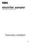
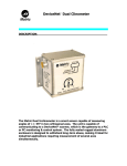
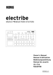
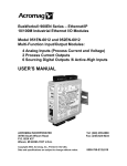
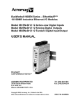
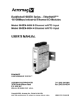
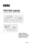
1
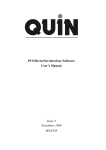
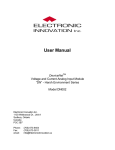
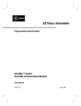
Network Communicator
NC100
DESCRIPTION:_____________________________
Add the convenience of
wireless operator control to
your DeviceNet* system using
a NetComm 100 base unit.
The NetComm 100 brings the
flexibility and productivity of
ergonomic remote control to
complex DeviceNet*
processes.
Network Communicator 100
MODULE
NETWORK
I/O
MODULE
The NetComm 100 is a base radio that receives operator commands
from a wireless handheld transmitter and makes them available as a
DeviceNet* object. Using the NetComm 100 and a TriggerPad
handheld, an operator can interact with a DeviceNet* system at a
typical separation of 300 feet. This product is ideal for interactive
systems, system maintenance, and automated processes that require
occasional manual override.
Wireless
Operator
Control
NetComm
TriggerPad
Trunk Line
Terminator
Tap
I/O BLOCK
NODE
SCANNER
NODE
MOTOR
CONTROL
NODE
SENSOR
NODE
SPECIFICATIONS:___________________________
•
•
•
•
•
•
•
•
•
•
•
•
•
•
•
•
•
•
•
•
•
•
Standard DeviceNet* node
Configuration using DeviceNet*
Rugged aluminum enclosure
Panel mount flange
Supports a variety of Matric handstations
16 bit CPU with CPU watchdog
Baud rate (125K, 250K, 500K)
Powered by 11-24VDC +/- 5% (DeviceNet)
Power consumption .66A at 11VDC worst case
In range / Out of range indicator for site mapping
Power indicator
Network status indicator
900MHz one way radio with 8 channels
Fragmented Explicit Messaging supported
Operational range of 0 - 300 feet*
Remote antenna mount up to 30 feet
Size: 5 1/4 X 5 3/4 X 3 Inches
Weight: 1 Lb 10 Oz
Five pin male mini connector
Operational temperature 0°C to 70°C
Storage temperature -40ºC to 85ºC
DeviceNet Product Catalog Number 941
*Typical specified range, actual range is dependent upon conditions and transmitter
specs
APPLICATION:______________________________
A variety of handhelds are available for the NetComm 100. The TriggerPad 100 includes four durable mechanical switches, which provide
tactile feedback and over 1 million cycle operational life. The TriggerPad 105 features eight membrane switches and a two digit LED display.
The TP-105 display can be used to set a value that is transmitted to the
NetComm. The value is simply an additional byte of data along with
the switch states that is available at the NetComm for use by the DeviceNet* scanner for application programming. Uses include setting a
speed value, a count, or identifying what equipment the handheld can
control. TriggerPad handhelds are made of rugged molded plastic, use
durable switches (over 1 million cycles), and typically provide more
than one month of battery life using standard AA batteries.
A risk assessment should be performed before implementing any new
control application. During risk assessments it should be noted that in
applications that require emergency stop a different model of remote
control or a different emergency stop method (pull cord, light curtain,
etc.) should be employed.
The Network Communicator employs 900 MHz radios that support 8
channels so that multiple independent systems can be implemented in
relatively close proximity with one another as shown below. Refer to
the “Placement” section of this manual for further details regarding RF
proximity issues.
TriggerPad
on Channel X
NetComm
on Channel X
TriggerPad
on Channel Y
NetComm
on Channel Y
DeviceNet* Trunk Line
Multi-Channel Multi-Operator
Application
The NetComm 100 supports an open RF messaging scheme that simply
responds to messages that provide the required header and CRC. RF
messages that are received simultaneously cannot be interpreted and
are ignored. This approach provides a high degree of data integrity
and flexibility, but does not guarantee message reception or discriminate between the sources of received messages. Consequently, the
NetComm 100 suitable for multi-operator applications, but does not
provide the continuously maintained RF link required for emergency
stop applications.
TriggerPad
TriggerPad
TriggerPad
NetComm
DeviceNet* Trunk Line
Single Channel Multi-Operator
Application
The actual range available at any given site is dependent upon a
number of RF related variables. Structural components such as steel
decking, earth tunnels, antenna placement, and metal walls or
equipment can effect the quality of RF transmissions. Also, radiation
sources such as other radio systems, high power switching, and
magnetic fields can also effect the quality of RF transmissions. A site
assessment should be performed at any site where any new RF control
is to be installed. Refer to the “Placement” section for details
regarding radio issues, site assessment, and optimal antenna
placement.
The NetComm 100 is housed in a sealed aluminum extrusion with
flanges for panel mounting. The sealed enclosure allows the
NetComm to be mounted in a control case or externally where it may
be exposed to weather.
A DeviceNet configuration/commissioning tool such as Rockwell’s
RSNetWorx, DeviceView, or SST’s Node Commissioning Tool is
required to prepare the NetComm for service.
The NetComm conforms to the “Predefined Master / Slave Connection
Set” as presented in the DeviceNet specification. In particular, the
NetComm participates as a slave device in the I/O Poll Command /
Response Message sequence. The NetComm ignores any data in the
Poll Command and considers it a trigger to return a response.
A poll response message containing four data bytes is sent from the
NetComm (slave) to the scanner (master) in response to a poll
command message. The poll response message contains the state of
the handset buttons, the type of handset, the battery status, and a
one byte value as detailed following field chart. The state of the
handheld buttons is given in a bitmap form. The switch numbers of
the bitmap correspond to the positions shown in the handset
diagrams.
Poll Response Message
Byte 0 (Status):
bit 7 - 1 = Low Battery in handheld
bit 6 - 1 = Receiving Data
bit 5 - not used
bit 4 - not used
bit 3 - not used
bit 2 - not used
bit 1 - not used
bit 0 - not used
Byte 1 (Button presses):
bit 7 - Sw 8
bit 5 - Sw 6
bit 4 - Sw 5
bit 3 - Sw 4
bit 2 - Sw 3
bit 1 - Sw 2
bit 0 - Sw 1
Byte 2 (Decimal numerical value):
0 - 99 (as shown on TP-105 display)
Byte 3 (Remote type):
00hex = TriggerPad 100
01hex = TriggerPad 105
1
2
1
2
4
3
3
7
5
4
8
6
TP-100
TP-105
CONFIGURATION:___________________________
All configuration of the Network Communicator is performed via
DeviceNet* using a configuration device and explicit messages.
Definitions of the objects used to operate the NC100 are given below.
Once configured, the handset data is retrieved from the NC100 during a
poll command-response sequence.
Identity Object (Class 1, Instance 1):
The Identity Object is used to get information (attributes) about the
NC100. These attributes are read only.
Attribute 1:
Attribute 2:
Attribute 3:
Attribute 4:
Attribute 5:
Vendor ID: This attribute contains Matric’s ODVA
vendor identification number, 229.
Device Type: This attribute contains the ODVA device
profile assigned to the NC100. The NC100 is
considered type 24, Human-Machine Interface.
Product Code: This is the part number of the NC100.
The Matric part number is 500-0941 and the product
code is 941.
Revision: This attribute shows the version of this
NC100 unit. Two bytes are used to contain the digits
before and after the decimal place, ie Revision 1.1.
Name: This attribute contains the ASCII characters of
the product name, NetComm 100.
DeviceNet Object (Class 3, Instance 1):
The DeviceNet Object is used to get and set data pertaining to how the
NC100 interfaces with the DeviceNet network.
Attribute 1:
Attribute 2:
MAC ID: This attribute contains this unit’s unique
address on the DeviceNet. It must be a value from 063 and the default setting as shipped is 63.
Baud Rate: This value sets the baud rate of the NC100
and should match the baud rate of the network. The
codes used to specify the baud rate are shown below.
The default baud rate is 125K baud.
0=125K baud
1=250K baud
2=500K baud
Assembly Object (Class 4, Instance 1):
The Assembly Object collects the handset data used in the Poll
Response Message. These attributes are read only.
Attribute 3:
Handset Data: This attribute contains the 4 bytes of
data in the same structure described as the Poll
Response Message.
Parameter Object (Class 15, Instance 1):
The Parameter Object contains configuration information required by a
DeviceNet product. This object is used by the NC100 to configure the
radio channel used to communicate with a handset.
Attribute 1:
RF Channel: This attribute is the radio channel used to
communicate with a handheld transmitter. When used
with a TriggerPad handheld it should be set to a value
from 0-7 that corresponds to the handset being used.
Vendor Specific Object (Class 100, Instance 1):
The Vendor Specific Object contains information used by the NC100.
This is an optional object and is included in this manual for reference
purposes only.
Attribute 1:
Attribute 2:
Attribute 3:
RF Channel: This attribute is the radio channel used to
communicate with a handheld transmitter.
Temperature, Fahrenheit: This is the internal
temperature of the NC100. This reading is not
calibrated.
Temperature, Celsius: This is the internal temperature
of the NC100. This reading is not calibrated.
Electronic Data Sheet (EDS) File:
The EDS file for the NC100 is available on the Matric web site or can be
emailed upon request. It is printed here for your convenience.
$
[File]
DescText = "Eds File for Netcomm 100";
CreateDate = 10-19-2000;
CreateTime = 14:25:07;
ModDate = 11-07-2000;
ModTime = 10:17:26;
Revision = 1.0;
[Device]
VendCode = 229;
VendName = "Matric Limited Inc.";
ProdType = 24;
ProdTypeStr = "HMI";
ProdCode = 941;
MajRev = 1;
MinRev = 1;
ProdName = "Netcomm 100";
Catalog = "500-0941";
[IO_Info]
Default = 0x0001;
$ Poll Only
PollInfo=
0x0001, $ Poll Only
1,
$ Default Input = Input1
1;
$ Default Output = Output1
Input1 =
4,
0,
1,
"Input1",
6,
"20 04 24 01 30 3",
"Data Input";
"No Output";
EDS File continued:
Output1 =
0,
0,
1,
"Output1",
6,
"20 04 24 02 30 3",
"No Output";
[ParamClass]
MaxInst = 3;
Descriptor = 0;
CfgAssembly = 0;
[Params]
Param1 =
0,
6,
"20 03 24 01 30 01",
0,
8,
1,
"MacId",
"Node",
"Address",
0,63,63,
1,1,0,0,
0,0,0,0,0;
Param2 =
0,
6,
"20 03 24 01 30 02",
0x0002,
8,
1,
"Baud",
"Kbps",
"Bit Rate",
0,2,0,
1,1,0,0,
0,0,0,0,0;
EDS File continued:
Param3 =
0,
6,
"20 64 24 01 30 01",
0,
8,
1,
"Rx Channel",
"Channel",
"Value",
0,7,1,
1,1,0,0,
0,0,0,0,0;
[EnumPar]
Param2 =
"125 KB",
"250 KB",
"500 KB";
$ Enumeration Text for Baud Rate
INDICATORS:______________________________
The NC100 provides three diagnostic L.E.D. indicators. The L.E.D. are
labeled “Module”, “Network”, and “I/O”. The behavior of these
indicators conforms to DeviceNet* and is described below. Refer to
“The DeviceNet* Communication Model and Protocol” Chapter 8 for
complete details regarding DeviceNet* states and indicators.
Module Indicator
In general, this indicator shows the status of the NC100 unit itself.
For This State:
The LED is:
To Indicate:
No Power
Off
Device Operational
Green
Device In Standby
Flashing Green
Minor Fault
Flashing Red
There is no power applied to
the device.
The device is operating in a
normal condition.
The device needs
commissioning due to
configuration missing,
incomplete, or incorrect.
The device has a recoverable
fault.
The device has an
unrecoverable fault and may
need to be replaced.
The device is in self test.
Unrecoverable Fault Red
Device Self Testing
Flashing Red/Green
I/O Indicator
In general, this indicator shows the status of communication between
the NC100 unit and the handheld transmitter.
For This State:
The LED is:
To Indicate:
I/O Inactive
Off
Not used.
Green
Flashing Red
The NC100 is receiving data
from a handset.
The NC100 is not receiving
data from a handset.
Not used.
Red
Not used.
Flashing Red/Green
Not used.
Flashing Green
Network Indicator
In general, this indicator shows the status of the communication link
between the DeviceNet* network and the NC100 unit.
For This State:
The LED is:
To Indicate:
No Power/ Not
Online
Off
Online, Not
Connected
Flashing Green
Link OK
Green
Connection
Time Out
Critical Link Failure
Flashing Red
Communication
Faulted
Flashing Red/Green
There is no power applied to
the device or the device has
not yet completed power up
testing.
The device is online, but has
no connections to other
nodes.
The device is online, and has
connections to other nodes.
One or more I/O connections
have timed out.
The device has detected an
error that has rendered it
incapable of communicating
on the network.
The device has detected a
Network Access error and
has received an Identify
Communication Faulted
Request – Long Protocol
message.
Red
INSTALLATION:_____________________________
The NetComm 100 can be bolted directly to a control panel using the
mounting flanges. See the diagram below for mounting dimensions.
Antenna
DeviceNet*
0.59
1.16
2.44
3.56
4.75
See Detail A for
mounting hole
dimensions
1.16
0.59
5.66
0.66
1.38
1.53
1.44
0.66
0.28
0.75
4.16
0.75
0.66
Detail A
5.06
0.30
0.30
The NetComm 100 provides a sealed male (pins) mini style connector
that complies with the physical standards for DeviceNet* connectors. A
DeviceNet* tap is used to interface to the DeviceNet* trunk line. The
pinout for the connector is shown below.
5
4
1
2
3
1 - Drain
2 - V+
3 - V4 - CAN_H
5 - CAN_L
PLACEMENT:_______________________________
The NetComm 100 is an FSK radio receiver that operates in the 902928 MHz band. Eight channels are provided for separation in adjacent
applications. Multiple transmitters may be active on separate channels
so long as an adjacent channel’s signal does not enter the receiver at a
level exceeding the rejection capability of the receiver. The effective
rejection capability of the NetComm is dependent upon RF factors that
vary from application to application. The rejection capability in a particular application may be determined through trial and error or through
a comprehensive site assessment.
A site assessment should be performed before any new radio system is
introduced into an operating environment. A thorough site assessment
of an area will discover active radio frequencies that could lead to contention and their sources.
For optimal performance, the antenna for the NetComm should be
mounted vertically, away from solid objects, and in the most visible line
of sight from the normal transmitting area.
THEORY OF OPERATION_____________________
The Network Communicator involves three basic components. The
first component is a Radio Module that receives switch state messages from a handheld transmitter. The Processor forms the switch
data into DeviceNet Objects that are made available via a DeviceNet
Interface.
TriggerPad Handheld Transmitter
Switch State
Processor
Switch State Messages
Radio
Module
DeviceNet
Interface
DeviceNet Objects
Processor
Switch State Messages
Radio
Module
Transmission of
Switch State Messages
Switches
DeviceNet Objects
NetComm Unit
DeviceNet
APPROVALS:_______________________________
The NetComm 100 has been tested and found to comply with the limits
for an intentional radiating device, pursuant to Part 15 of the United
States FCC Rules. Changes or modifications not expressly approved by
Matric could void the user’s authority to operate the NetComm 100.
Matric
2099 Hill City Road
Seneca, PA 16346
814-677-0716
www.matric.com
NetComm 100 Manual v3.pub
*DeviceNet is a registered trademark of ODVA
Copyright 2001, Matric
Printed in USA, 8/8/02