1
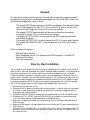
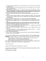
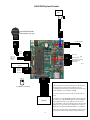
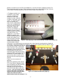
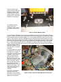
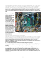
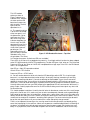
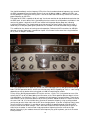
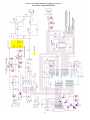
Revised 25Apr2011
N4YG
Direct Digital Synthesis
System
Corsair II Installation
&
Users Manual
1
General
This document contains information that will guide you through the installation process
and provide technical details and operating procedures for the N4YG DDS system. This
installation described here is one in which:
-
-
The original SPOT button becomes the DDS control button. This button will allow
you to switch between the two VFOs, VFO A and VFO B. With it you can also
select the SPLIT mode and save the VFO values to memory.
The original OFFSET potentiometer will become the Receiver Incremental
Tuning (RIT) control. This is the same function actually.
The original RF ATTN LED is used to indicate that SPLIT operation has been
selected when lighted.
The original OFFSET LED is used to indicate that VFO A is active when lighted.
The original PROCESSOR LED is used to indicate that VFO B is active when
lighted.
There are four main sections:
Step-by-Step Installation
Notes Regarding Corsair PTO Removal and DDS Integration – by W0CCA
Operating Instructions
Technical Information
Step-by-Step Installation
The instructions which follow outline all the steps for completing the installation in the Corsair II.
When all these steps are completed, the Corsair should be ready to operate. You should refer to
the pictorial at the end of this section and also to the section following this one. It provides
insights by W0CCA regarding his experience after having completed the installation. You will
find this to be a valuable aid as you go through the process. It is assumed at this point that the
DDS board has been completely assembled and that the retrofit for 8-18 VDC supply has been
installed on the board. (NOTE: This board was originally designed to have 12.6 VAC supplied.
The 8-18 VDC retrofit allows DC prime power to be supplied from the Corsair II.)
1. Remove the PTO from the Corsair.
2. Prepare the SPOT button by removing existing connections. It may be necessary to remove
this switch in order to prevent damage to the switch while removing existing connections
and making the new connections.
3. Prepare the OFFSET button by removing existing connections. Refer to the W0CCA notes.
4. Prepare the ATTN, OFFSET, and PROCESSOR LED assemblies by removing the drive
lines. The driver networks will be retained (refer to W0CCA notes).
5. Mount the Incremental Encoder in the space where the PTO shaft was removed (refer to
W0CCA notes).
6. Mount the DDS board in the space below the chassis where the PTO was removed (refer to
W0CCA notes).
7. Connect the wire attached to pin 1 of J6 to the same 8 VDC source which powered the PTO
previously. You may want to take the 8 volt regulated source from any one of a number of spots on
that side of the radio
2
8. Connect the wire attached to pin 2 of J6 to a convenient chassis ground in the Corsair (refer
to W0CCA notes).
9. Connect the small output coaxial cable attached to J7 to the VFO/Mixer input in the Corsair
(refer to W0CCA notes).
10. Connect the wire coming from pin 1 of J1 to one of the terminals of the DDS control switch
(Corsair SPOT button). This switch will probably need to be removed from the panel in order
to prevent damage while connecting this wire as well as the ground wire in step 12 below.
11. Connect the wire coming from pin 5 of J1 to lug A of the RIT pot.
12. Connect a wire between lug A of the RIT pot and the open terminal of the DDS Control
switch.
13. Connect the wire coming from pin6 of J1 to the “R voltage” of the Corsair. The easiest place
to connect to the R voltage at lug C of the RF GAIN pot near the DDS board and above the
passband board.
14. Connect the wire coming from pin 7 of J1 to the center lug or the RIT pot (lug B).
15. Connect the wire coming from pin 2 of J1 to the drive point for the OFFSET (VFO A) LED.
16. Connect the wire coming from pin 3 of J1 to the drive point for the PROCESSOR (VFO B)
LED.
17. Connect the wire coming from pin 8 of J1 to the drive point for the RF ATTN (SPLIT) LED.
18. Connect one lead of the 470 ohm to lug C of the RIT pot. Then connect the wire coming
from pin 7 of J2 to to the other lead of the 470 ohm resistor.
19. Plug J1 into JP1 on the DDS board, making sure that pin 1 of J1 is aligned with the white dot
near JP1. The dot indicates the pin 1 end of JP1.
20. Plug J2 into JP2 on the DDS board, making sure that pin 1 of J2 is aligned with the pin 1 dot
near JP2.
21. Plug J4 (connected to J2), into the incremental encoder, making sure that the +, -, A and B
marking on the encoder are matched with those on J4.
22. Leave J6 disconnected for now.
23. Plug J7 into JP7 on the DDS board, making sure the pin 1 dot on the board is aligned with
the pin 1 marks on the connectors.
The final and most important step is to check everything carefully. You have probably already
noted that it is possible to plug any of the connectors backward or with some pins outside the
connectors.
- Check carefully and make sure the pin 1 markings on the connector housings are
aligned with the pin 1 markings on the board (white dots).
- Make sure that no pins are visible outside the connector housings.
With J6 disconnected from the DDS board, turn on the Corsair and check the voltage between
pin 1 and pin 2. It should read 12 volts and pin 1 should be positive.
Turn the Corsair OFF.
Connect J6 to JP6, being certain to align the pin 1 markings.
Turn the Corsair ON. Adjust the RF LEVEL potentiometer according to the procedure outlined
by W0CCA in the next section.
This completes the installation.
3
N4YG DDS System Pictorial
Input to
Mixer
INCREMENTAL
ENCODER
Incremental Encoder
connections may vary
J7
+A B–
12 VDC (Note 1)
J4
J6
GND
+5 VDC
MTA
MTB
Not Used
Not Used
RIT Pot +5
(Lug C)
Not Used
SPLIT LED
RIT Pot Wiper (Lug B)
R-Line (Note2)
RIT Pot Ground (Lug A)
Band PB (Note 3)
VFO B LED
VFO A LED
DDS Control PB (Note 4)
J2
J1
J3 Used Only For HW-101 Band
Sensor
+5 VDC
Sensor 1
Sensor 2
Sensor 3
Ground
J3
A B C
DDS Board
J5
16
1
Notes
1. The Retrofit fix for 8-12 VDC input power has already been
incorporated if you purchased an assembled. If you are
assembling your board, parts are included for the retrofit circuit
and the instructions are provided accordingly.
Pot Detail – Rear View
2. R-Line is +10.6 Volts in the Rx mode and 0 Volts in the Tx
mode.
LCD Display
(optional)
3. Connects to an optional BAND pushbutton switch. Each time
this button is pressed, the BAND advances. After reaching the
upper 10M band, it rolls over to 160M. The processor must
have an indication of the current band in order to drive the LCD
display. The Corsair II (and others) already have a frequency
display, thus the LCD and the band indication is not required.
4. The other side of the DDS control pushbutton switch must be
grounded. Run a wire from the switch to lug A of the RIT pot.
4
Corsair PTO Removal and DDS Integration – by W0CCA
Modified 02/23/11 by W0CCA
This set of instructions applies to the Ten Tec Corsair II PTO replacement with a DDS by N4YG. Joe,
N4YG (www.n4yg.com, [email protected]) has done a fine job of designing and building a product that has
adequate output, is very stable and clean, and can be adapted to a wide variety of VFO needs. If you
wish to adapt this "fix" to other Ten Tec PTO radios, you will have a similar routine (Omni C, Triton, etc.)
but may have glitches or difficulties not presented by the Corsair II.
Most Corsair II’s have had one or more PTO rebuilds. Some many more. This DDS installation has the
double advantage of forever leaving that activity behind and adding important new features the Corsair
never had in A/B VFO operation and Split operation, a definite improvement over the Tx/Rx Offset
technique previously used for working DX “up 2”, or up 10 for that matter. This is a very simple and neat
operation because all of the unusual frequency adjustments and conversions prior to LED readout in the
Corsair are done further down the conversion chain and this radio can be operated just as well with a
simple 5.0-5.5 mhz VFO. There is no need for a new readout as a result. The 100 hz readout resolution is
adequate for me in determining my RIT offset.
This set of instructions applies to the Ten Tec Corsair II PTO replacement with a DDS by N4YG. Other
Ten Tec PTO radios will have a similar routine (Omni C, Triton, etc.) but may have glitches or difficulties
not presented by the Corsair II. I have successfully completed the conversion in a Corsair I and Omni
D/Series B with very minor differences. This is intended to be a reversible operation. Once you have the
DDS in and operational, you will not pine for the old PTO, however.
1. Remove top and bottom covers.Carefully disconnect the push in connectors for the speaker before
taking that cover section away.
2. Remove front panel. The tuning knob and others need a very small Allen wrench and the Bandswitch is
a slightly larger size. They seem to be SAE sized and not metric. When removing the tuning knob, keep
the felt washer, and gently slide off the skirt ring behind, being careful to gather the tension spring should
it come off. Remove all other knobs, remove four screws at corners. When sliding the panel off disconnect
the jumper for the meter at the meter driver board. Be careful as the plastic insert along the top of the
panel covering the meter and LEDs slides out quite easily and could hit the floor and break. Hang onto it.
Put 1. And 2. In a safe place. Except for speaker and S meter the radio, while primitive looking, is still fully
functional.
3. Find the PTO, bottom
center (Figure 1). It is held by
the two screws on the front
sub panel. Remove them and
save the grounding spring
wires. Gently pull the PTO out
a little and look at the wires on
the side. It is better to
unsolder these than to cut
them, but either will work.
They are not organized in the
same order as on the
schematic. From the left 1) is
signal out with ground, 2) is 8
volts regulated supply, 3) is
the enable connection which
is jumpered on the back of the
radio. 4) is the offset wire
which applies a varying
voltage to the PTO for RIT. 5)
is the Shift wire which
5
Figure 1. Bottom of Corsair II With Covers Removed
performs the 10 Khz shift in the PTO for the oddball 10, 21 and 28 mhz bands. (apparently done by Ten
Tec to avoid strong spurious signals) Tape or protect all of these wires and pull out of the way. If you are
serious about this being a permanent fix you can find their origins and remove them.
4. The biggest variable in this
installation is your encoder
and shaft. I found that my
encoder was JUST long
enough for a knob if mounted
as follows: I fabricated a small
scrap 1” x 2” aluminum plate
with a hole drilled in the
center for the encoder body to
fit flat inside, and drilled outer
holes for the two PTO mount
screw holes. I used 4-40
hardware. This plate will
mount on the OUTSIDE of the
sub panel, as there is plenty
of space between that and the
main panel (at least 1/8”,
maybe 3/16”). If you mount it
INSIDE the subpanel, your
encoder shaft may not be long
enough. My encoder fit nice
and snugly against that plate
and the existing hole in the
Figure 2. PTO ready to go on the shelf (Labeling is useful for any future use.)
sub panel was large enough
to accommodate it without
interference. A thin backing washer was placed on the inside to keep the encoder perfectly aligned and
the encoder is now nicely mounted on the subpanel. You can test this by putting the main panel on sitting
on the spacers and putting your knob on
and seeing how it looks. I recommend
making sure that is satisfactory before
proceeding. Putting the panel on and off
including knobs, too many times, is
exhausting. At the worst you may have
to get your nibbler out to slightly enlarge
the hole the PTO went through. This
wont hurt the radio as a return to PTO
operation will cover anything you do to
that hole.
Figures 3 and 4 summarize this
operation.
Remove the grounding screws and the
PTO is free. Note the Spot push button
which will become your DDS command
button and the Offset pot, easily
accessible, to left, which will become
your DDS RIT pot. Note the two shaft
diameters. Your new encoder will not
have the same outer shaft diameter
and you will need to consider either
drilling out the Corsair knob or
adding another knob with standard ¼” i.d.
Figure 3. PTO Shaft and Grounding Springs
6
Figure 4 shows my new
aluminum plate on which the
encoder is mounted. There
are probably other equally
suitable solutions. Anything
you place here will be totally
hidden by the outer panel.
This completes the only
“difficult” part of this
installation. Figure 5 shows
the encoder in and ready to
go.
Figure 4. Encoder Mounting Plate
5. You will find the DDS board fits very nicely on the bottom of the chassis in the PTO location shown in
Figure 5. Carefully move wires around and there will be three mounting positions available with the upper
left hole toward the panel left without support. This is not a problem. My board is quite stiff on the three
spacers. Choose spacers and small self tapping screws to attach the board, carefully drilling the chassis.
Move all existing wires carefully out of the way. I temporarily removed quite a few of the Corsair jumpers
to “clean up” the work area. Make sure your spacer length does not impede connection of the encoder
pins, i.e. don’t make the spacers too long. I used about 1/8” spacers. And 4-40 or smaller self tapping
screws. Orient the DDS board so that the pins for the encoder face the right, looking at the front panel, or
toward the bandpass board,
lower right in picture. This will
leave other pins in favorable
orientation.
6. The offset pot for the Corsair
will become your new RIT pot.
The value as is is suitable
(about 20k). A 470 ohm resistor
is added in series to the+5v
side of the pot to prevent
possible rollover of the RIT.
Remove the offset wires and
tape them and label if you wish.
Run the new wires from the
DDS to the RIT pot. (the two
lever switches for Offset
Max/Min and Offset Tx/Rx will
cease to have function. You
might come up with another
use for these switches
someday).
At any time, if you become
confident that this DDS
changeout is a final step with
your Corsair, the wires that are
taped and saved could be
Figure 5. Interior View of Encoder Mounted on Front Panel
7
removed completely. I saved mine. I would guess I can get my radio back to PTO status in about 2 hours.
7. The Spot button, which I never used, I always got on QRG by ear, will be your A/B or Split button for
VFO choice. Remove the Spot wires and tape and label, you will have A/B operation now which the
Corsair never had. Wire the Spot button per the N4YG DDS instructions for the DDS button. Do not forget
that one side of the switch must be grounded by connecting a wire to the grounded side of the RIT pot.
This is a very ergonomic operation, as the spot button can be used by one finger as you tune on the main
knob.
Figure 6 shows the DDS
board installed in the
Corsair II. Yours may look
different as N4YG is
constantly improving and
upgrading this DDS.
8. The +12 v power jumper
is at the lower left. I routed
this wire to the rear of the
radio and picked one of the
+12 volt sources. (N4YG
Comment: It has been
found since this writing
that the +8 volt source
which preciously powered
the PTO is a better choice
for prime power and it is
located nearby.) There are
many in the radio. I made a
ground lug and connected
the power ground directly to
Figure 6. DDS Board Mounted in Former PTO Location
the board spacer at the
chassis. If you use
aluminum mounting
spacers, the board is self grounding at the +5 volt regulator.
9. The VFO signal wire runs to the double phono jumper at the rear panel. This is the simplest connection
location. You could also take the actual PTO injection wire to the mixer and directly connect to the DDS.
Keeping the jumper alive is good for going back to PTO someday, but if you don’t ever see having an
external VFO (after all you now will have internal A/B) a direct connection is better. Future VFO
experiments are possible if you leave the jumper arrangement in. You could have other external VFOs to
compare with the DDS for instance.
10. The Jumper harness from the encoder to the encoder jumper can be installed.
11. The main center jumper harness can be connected to the RIT, and Spot switch as per DDS directions
from N4YG. This is the most involved wiring. Using the existing Offset pot and spot switch makes this
very easy.
12. The R voltage wire connection can go anywhere this voltage is available. The R voltage wire
connection is best connected to the "C" lug of the RF gain control just next to the DDS board and above
the passband board.Check your Corsair schematic.The R voltage available in a lot of places. The R
voltage will switch your DDS from receive to transmit frequency with each keying of the rig, up to very
high speeds (I have only tested to 45 wpm) and do it cleanly. It will of course do the same when you are
in A/B/Split mode.
8
This LED readout
enclosure shown in
Figure 7 contains four
indicator LEDs. Remove
the cover and the LED
board easily comes out
with the cover. The ALC
light will be left
operational as is.
13. The remaining wiring
is to the LEDs at the top
of the front panel. I use
the Attenuation, Offset,
and Processor LEDs. I
don’t think using these
indicators degrades the
Corsair much. An SSB
operator will know if he is
using the Processor by
virtue of the Processor
pot being on. The
Attenuation with the RF
gain has always seemed
Figure 7. LED Readout Enclosure – Top View
redundant to me, I turn
the gain down. The Offset
isn’t functional anymore. So the three LEDs are “available”.
These LEDs in the Corsair II are toggled using normal +/- 5 volt logic and their function has been adapted
to the VFO A/B function by N4YG's PIC programming. The Attn LED goes “high” when on. The Offset and
Processor LEDs go “low” when on. N4YG has incorporated these logic steps in the PIC in the DDS board
and it is all straightforward.
Attn LED on = Split VFO operation enabled.
Offset LED on = VFO A active
Processor LED on = VFO B active
14. You will need to determine which wire from the LED board lights which LED. This is quite simple
because it is a simple board and the function wiring is all correctly lined up. (remember you are likely
looking at the board upside down !!) Consult the drawing for Board 80983 in your Corsair manual for
additional schematic help. You could use the junction pc board behind the LED enclosure to connect
these wires. I chose to solder them splice style because of my desire to keep the retroactive feature alive.
Carefully follow each wire from your DDS jumper to the appropriate LED wire and connect. With care it is
pretty simple. Carefully replace the cover on the LED enclosure being careful not to pinch any wires with
the aluminum top.
This should complete installation. Carefully check all wires for disturbance, make sure all the small jumper
plugs on the Corsair are still in, make sure your cut wires are adequately isolated, make a good thorough
look around for possible shorts, disturbed items, broken wires, spare screws, tools lying in the radio, put a
dummy load on the radio just in case it comes on keyed for some reason, and turn on the power. As in all
smoke tests be ready to kill the power if something odd is going on. The conservative thing to do would
be get the main panel back on so you can look at the s-meter and quickly change controls.
There is a lot of potential for moving a wire, causing some kind of new connection, accidentally pulling
one of the jumper plugs in the radio, etc. Never turn on power to a modified radio without first checking all
the above, and without being able to watch load current from the power supply. Blind smoke tests end
badly. In my experience, these unintended disruptions are what kill a modification, not the new circuitry.
9
You should immediately see the frequency LEDs of the Corsair readout whatever frequency was stored in
the DDS at programming on the band of choice. If you see 91.000 or 9.000 or -1.000 on the LEDs, you
are not getting VFO signal to the mixing chain. Turn off the radio and check wiring. Success will show the
proper frequency on the LEDs.
The output of this DDS is capable of 20 volts p-p. You do not need that for the double balanced mixer that
the DDS feeds. In fact it doesnt like it. Overloading the mixer creates lots of IM products and birdies in the
receiver. My advice is back off on the RF level control until the proper display drops out, indicating
insufficient DDS output. Then slowly tweak up on that pot until you have enough signal for the mixer. I
found that just a little past good signal injection was all I needed. I have not measured that p-p voltage.
This modification has almost no learning curve for operation. Follow the N4YG instructions for A/B/Split
operation using the Spot button. It couldn’t be simpler. I find it more intuitive even than using the buttons
on my Omni VI. Maybe I am biased.
This is my completed Corsair panel. As you can see, the 0-100 logging skirt is now gone from the tuning
knob. The DDS operation doesn’t suit the use of that anyway. With its capability for “fast” vs. “slow” tuning
depending on rate of rotation of the tuning knob, a 0-100 skirt would not be suitable.
For my version, N4YG programmed the RIT for plus or minus 1.5 khz. This is just perfect for me as I like
to leave the RIT set off just about 300 cycles from center as the 750 hz optimum bfo tone doesnt suit me.
I like 450-500 hz. Yet, with the 1.5 khz rit, if someone calls off frequency I can go find them. Those of you
who know the Corsair II know that because of the mixing scheme, 160,80,40, 30 and 17 meters all mix on
the same "side". 20, 15,12 and 10 the other. So to be on someones frequency using my offset method
you have to go to the "other side" with the RIT when changing bands. If you like "straight up 750 hz" tones
you will not have this problem. It is possible of course to adjust the product detector result at the BFO
crystal, but that causes other changes. That is left to the installerI will leave centering the RIT pot as an .
exercise for the reader, its not hard and simply a question of tightening the allen screw at the right
position. Generally, if your readout shows the same frequency key up or key down, you are in the center
of the passband.
10
Operationally, because the 10 Khz offset is not programmed in for the oddball bands, you will have to
tune up 10 khz when you switch to that band. Readout will be correct of course. But you have to tune
around a bit with the Corsair anyway because 30, 17 and 12 meters dont have their assignments on the
500 khz multiple. A small drawback to an otherwise very fine analog radio. The multiple speed action of
the encoder to my way of thinking actually makes, for instance, the 100 khz "spinup" to 30 meters much
faster than with the PTO. 12 meters requires a little more labor for the 390 khz "spinup"
Note: I did not mount the DDS board in a metal enclosure. I perused Mouser and Digikey and there are
several aluminum miniboxes available in the 3 ½” x 3 ½” size category. There may or may not be spurs
generated by the DDS that could be more effectively shielded using this approach. Only further testing
and operation will tell me if this is a need. So far I agree with N4YG, it isnt needed.
This is a very simple modification and I am confident some version of it will work with all Ten Tec PTO
radios, liberating you from PTO rebuild, warbly frequency, or in the case of a ham that simply put the
radio on the shelf because of lousy PTO action, a reborn radio. The DDS of course doesn’t “just” cover
5.0-5.5 mhz. The resonant circuits for each band and the conversion scheme will limit that success, but
should an excursion to a MARS frequency, etc., be in order, no problem.
I am not an electrical engineer, and have only a lot of years of homebrewing (and lots of Heathkits as a
kid!!) and tinkering under my belt. This modification should be easily accessible to anyone with a similar
background. If tearing into radios like this makes you queasy, then I would not recommend proceeding.
Cap Allen, W0CCA, Dolores, Colorado, 11/15/10, revised 02/23/11.
N4YG Comments
W0CCA has provide a service not only to me as I try to provide a useful product for the
Amateur Radio community, but also a valuable resource for all who value their Ten Tec
radios with aging VFOs. I wish to thank Cap for the work he has done in being the first
to complete the installation of the N4YG DDS into his Corsair II and for documenting his
work and experiences for your benefit. You would do well to read carefully and take
advantage of his experience. Cap has indicated, after reading his own description of his
experiences with his DDS installation, that his account seems more complicated than it
actually was.
11
Operating the DDS System
1. Controls
The only controls are the Main Tuning control (which rotates the incremental
encoder), the DDS control pushbutton and the RIT (OFFSET originally) control.
-
Main Tuning Control
The Main Tuning control rotates the shaft of the incremental encoder.
When the shaft is rotated, pulses are generated by the encoder and sent
to the processor on the DDS board. The processor code implements
variable tuning rate. Variable tuning rate is used so that very slow tuning
rates can be used for fine tuning and high tuning rates can be used to tune
rapidly across the band. Measured in Hz per revolution, the tuning rate is
256 Hz per revolution for very slow rotation and up to about 100 KHz for a
very fast rotation of the Main Tuning control. At a comfortable rotation rate
of about one rotation in 3 to 5 seconds, the tuning rate is about 2 to 3 KHz
per revolution.
-
DDS Control Pushbutton
The DDS Control pushbutton controls the operation of the two VFOs. In
very simplified terms, there are two numbers in memory which define the
frequencies of the two VFOs, VFO A and VFO B. Either A or B may be
designated for Rx and either may be designated for Tx. If the Rx and Tx
VFO designations are different then the SPLIT mode is in effect. When
first turned on, the values for VFO A and VFO B are given the values
stored in memory and the Rx VFO and Tx VFO will be VFO A. Let us say
for example that VFO A is set at 5.3579 and VFO B is set at 5.2222. When
you turn it on, you will see one of the frequencies. For 40 meters for
example, “7357.9 KHz” would be displayed if VFO A is the current VFO. If
you "Single-Click" the button as you would single click a mouse, the VFO
B frequency appears. Do it again and the VFO A value appears on the
display. In addition to the “Single-Click”, you may also “Double-Click”,
“Long-Click” and “Very-Long-Click”. The “Double-Click” is again like
double clicking with a mouse. The “Long-Click” is a pushbutton closure
lasting more than about a second. The “Very-Long-Click” is a closure
lasting about 2 seconds or more. Each time you do any of these, the
values for VFO A and VFO B are saved to flash memory and the following
also occurs:
12
-
"Single-Click' complements both Rx and Tx VFOs.
-
"Double-Click" complements the Tx VFO. This effectively toggles
between SPLIT and UNSPLIT
-
"Long-Click" equates VFOs to the value of the Rx VFO.
-
“Very-Long-Click” no action other than to save current values
When the unit is turned off and then back on again, VFOs A and B will
have the values as when they were last saved.
-
RIT Control
The RIT control is the same control that is labeled OFFSET. It has the
same function as it did with the original PTO. At the center of the rotation
of the pot, there is a small deadband where rotation of the control causes
no change in frequency. To either side of the deadband +/- 1500 Hz tuning
of the receive frequency is available.
2. Indicator LEDs
The function of three of the original indicator LEDS, RF ATTN, OFFSET and
PROCESSOR have been changed to SPLIT, VFO A and VFO B respectively.
As mentioned above, when the Corsair is first turned on VFO A will be the Rx
and Tx VFO. Thus only the OFFSET LED will be on initially. If you “Click” the
DDS Control button, the VFO A LED will go off and the VFO B LED will come
on. Click again and VFO A is on. Each time you Click the lighted LED will
switch between A and B. If you transmit, there is no change because the Rx
and Tx VFOs are the same. If you Double-Click, you will see the SPLIT LED
come on. If you transmit while in the SPLIT mode, you will see one (A or B)
come on and the other go off.
13
Technical Information
The N4YG DDS system contains a power supply, a microcontroller chip, a direct digital
synthesis chip and an output amplifier. The microcontroller provides an interface for a
liquid crystal display (LCD) which is optional and normally not required for the Corsair II
if its display is functional. The system provides an RF output frequency in the range
from a fraction of a Hz to over 15 MHz. The output of this particular unit is limited to a
range of approximately 750 KHz. For legal operation or the Corsair II within the amateur
bands the output is between 5000 and 5500 KHz. The general specifications are shown
below.
Frequency Range
4900 to 5650
KHz
Short-Term Stability(typical)
1
Hz
Long-Term Stability(typical)
less than 50
Hz
RF Output Voltage
0 to 20
Volts Peak-To-Peak
Frequency Resolution
0.0116
Hz
Tuning Input
Optical Incremental Encoder (128 Pulses/Revolution)
Frequency Update Time
Spurious Output
~100
microseconds
60 dB or more below primary output
Power Requirements
12 VDC @ approximately 200 mA
The power supply was originally designed to operate from an input of 12.6 VAC. A small
modification consisting of 2 resistors and a capacitor has been added and several
components are removed in order to use a DC input voltage, 8 to 18 VDC.
Approximately 200 milliamperes from the Corsair 8 volt source which originally powered
the PTO. This is the best power source for the Corsair version of the DDS board.
The 16F877A microcontroller controls all the processes on the board. The various
inputs include:
-
Incremental encoder
-
DDS Control Pushbutton Switch
14
-
Transmit/Receive Logic Line
-
RIT Tuning Voltage
-
Band Sensor (HW-101 only)
With these inputs, the microcontroller continually tracks all frequency and mode
changes and provides data to the AD9835 DDS processor regularly update its output
frequency. Data is provided at the LCD interface port which will display VFO
frequencies and other information if a LCD is connected to the port.
The RF output from the DDS processor is less than 300 millivolts, which is insufficient to
drive the Corsair mixer. The output amplifier can provide and RF output up to 20 volts
peak-to-peak which is continuously adjustable. Generally the output is adjusted to the
minimum level required for full, reliable performance.
15
N4YG DDS Board Schematic Diagram (Corsair II)
Before Power supply Modification
16
N4YG DDS Board Schematic Diagram (Corsair II)
After Power supply Modification
17