1
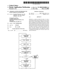
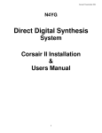
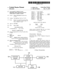
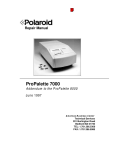
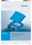
7
I
4
NW
The Microprocessor in the Biological Laboratory
Robert L. Schoenfeld
William A. Kocsis
Norman Milkman, and
Gordon Silverman
Rockefeller University
History
The use of microprocessors in the biological laboratory
is a logical result of the evolution of computer use in
the biomedical sciences. In 1963, H. K. Hartline and Floyd
Ratliff, working at Rockefeller University in New York
City, hooked up a CDC 160A computer as a generalpurpose laboratory instrument for data acquisition during
their experiments on vision.' For stimulus control, they
used a digital programmer constructed from commercially
available discrete transistor logic circuits.2 The work in
the Hartline-Ratliff laboratory was a continuation of
earlier work done by Hartline on inhibitory interaction
in the horseshoe crab's eye, for which Hartline shared
the Nobel Prize for Physiology and Medicine in 1966,
with Wald and Granit.3
Figure 1 shows the subsequent exponential growth of
the use of computers in the biological laboratories at
Rockefeller University. In the early years, the laboratory
computer was used in studies of human learning, animal
and insect behavior, and studies of various sensory
systems as well as the central nervous system. The use
of computer techniques in biochemistry developed more
slowly, but has now become a major instrumentation
technique in this and related disciplines. Although this
figure illustrates the history of laboratory computers in a
single institution, it may be used as an example of the
use of computers and the expanding role of microprocessors
in other biological research institutions and laboratories.
Computers and biological disciplines
To the best of our knowledge, the earliest and most
widespread use of computers in biology was in the study
of either the behavior of whole organisms, or in investigations of sensory or central nervous system functioning.4
We shall discuss the use of minicomputers and micro-
processors in that area of work later on in this article.
However, the use of computer techniques in biochemistry,
which is developing very rapidly, will be taken up first.
56
35 F
30 F
25 F
201LL
m
15 F
10o
5
6
63
65
67
69
71
73
75
YEAR
Figure 1. Growth of laboratory computers at Rockefeller
University, 1963-1976.
Biochemistry. With the discovery of the double helical
structure of the DNA molecule, the genetic building block
of the organism, there has been rapid progress in the
study of the constituent organic molecules of living tissue.
The importance of these studies has been that they have
given us three-dimensional models of important organic
molecules; these models, together with an understanding
of chemical bonds, electrical forces, and the rules of
COMPUTER
quantum physics, have enabled biologists to understand
processes of crucial importance in the body's response to
discease.
The techniques involve the use of a number of
instruments such as those used in gas-liquid chromatography and amino-acid analysis to separate constituents
of organic molecules. Techniques such as optical spectroscopy, mass-spectrography, electron-spin resonance, and
nuclear magnetic resonance are used to analyze atomic
and ionic components of organic molecules, and their
spatial organization can be studied directly by X-ray
diffraction.
The use of computers associated with these instruments
developed slowly, because of the cost and complexity of
both the chemical instruments and the computers available
to connect with them. At that time, the computer
architecture was not designed for ease in interfacing
computers to laboratory equipment. The requisite skills
for doing the job were also in short supply. As the
manufacturers of minicomputers provided bus structures
and standardized control signals to make interfacing
easier, these costs decreased. Researchers developed the
skills necessary to design the hardware and write the
programs to provide computerized control and data
acquisition facilities for chemical instrumentation.
At present, the whole spectrum of computer systems
is used in analytical chemistry.5'6 The use of microprocessors for instrument control is already well established.
Minicomputers are used for data acquisition and the
programming of serial assays or the handling of large
numbers of samples. Large and powerful computers
are required for sophisticated data analysis tasks that
involve either large amounts of data or complex mathematical computations. Many techniques, such as nuclear
magnetic and electron-spin resonance, involve extensive
mathematical calculations such as the Fast Fourier
Transform and curve fitting by least squares techniques.6
of light stimuli was set using manual switches and
plug-boards on a digital programmer, providing three
independently switched light channels.2 The equipment
included lens systems, micromanipulators, and provision
for light and electrical shielding. Similar experiments are
now done in the same laboratory with modern minicomputers. Recently, a microprocessor-based, spatially
modulated visual stimulator has been placed into service.
The continuing effort in this laboratory is to study the
spatial and temporal properties of the eyes of animals
at various levels in the evolutionary scale.:
In another laboratory, a remote Linc 8 computer
monitored the responses in a cat's vestibular neurons as
the cat was rocked according to a pres'cribed waveform
in a hydraulically controlled platform.8 Subsequently,
these and similar studies of the neural concomitants of
motion have been instrumented through a DEC PDP 11/45
computer which runs experiments in two separate locations
simultaneously using a real-time multiprogramming system
DEC RSX-11M. This setup first required extensive interfacing of specialized laboratory peripherals -constructed
from TTL logic components. Continuing studies of motion
and the control of gaze have now generated the need for
very sophisticated kinds of microprocessor stimulators as
peripheral devices to the laboratory minicomputer.
Microprocessors provide an inexpensive and convenient
method to process samples sequentially or to adjust
parameters of electric and magnetic fields or to displace,
rotate, or collect samples or effluents mechanically. In
current practice, a number of separate instruments are
combined to accomplish more complex analyses. One
example is the use of a gas-liquid chromatograph, followed
by a mass spectrograph.7 In this method, as different fractions of a mixture are collected through the chromatograph,
each component is separately analyzed by the mass spectrograph in terms of its mass components. Such a process
must be monitored and controlled automatically. Currently, many of these tasks are done with minicomputers,5
but in the future, microprocessors will be more flexible
and more cost-effective for this application.
Physiology and psychology. Figure 2 is a rough sketch
that combines the features of a number of laboratory
experiments in physiology. Two microprocessor instruments are shown. One is a general-purpose stimulator
that controls a paw manipulator linked to a feeding tube.
Also shown, but not necessarily for the same experiment,
is a control for auditory, visual, and electrical stimulation.
A second microcomputer-based device is used as a
data acquisition system connected to electrodes in the
brain and heart muscle. The two computers are tied
together to indicate that there is synchrony and control
between stimulus and response.
In the past, the same components were constructed
using general-purpose minicomputers. In the earliest
computerized experiments at Rockefeller University, a
CDC 160A computer was used to acquire data from
experiments on the horseshoe crab's eye.' The duration
May 1977
Figure 2. Physiological experiment using microprocessor
devices.
In studies of learning, the experimental animal very
often is human. A typical setup consists of a visual
display terminal or oscilloscope with auditory output. The
response is indicated by one or more pushbuttons. One
may study recall of displayed words or measure reaction
times to combined visual and auditory stimuli for words
or textual material. Several minicomputer setups have'
been used in this research over the last decade.9
57
In these and other psychological experiments the computer system and the programming become rather complex
as the sophistication of stimuli, controL and data acquisition
increases. An example is a visceral learning experiment.
In this experiment, a rat's heartbeat is monitored while
an attempt is made by a combination of auditory signals
and electrical shocks to force the animal to increase or
decrease its heart rate. In such experiments, while it is
technically possible for a single laboratory minicomputer
to control the experiment, and to acquire and process
the data, the cost and inflexibility of the software and
the hardware are excessive. By building a microprocessorbased electrical and auditory stimulator as a low-cost
minicomputer peripheral, the system can be made much
more modular. The cost of the ongoing development and
changes in the experiment is thereby much reduced by
distributing the computer functions. The experiment is
more flexible and easier for the programmer and scientist
to understand and modify.
In some cases the use of a general laboratory minicomputer is unwarranted because the capacity and facilities
of a typical system are excessive for the needs of the
particular experiment. For example, the study of eating
and drinking behavior is important because it sheds
light on such pathological conditions as obesity and drug
addiction. The same techniques are used also in the study
of the systemic side effects of various drugs. Such studies
are currently done using minicomputers hooked up to
feeding and licking detectors as well as activity cages.
However, the data rates for such studies are very low,
so that microprocessor-based instruments either with
concurrent data recording or modest mass storage capabilities could do the job as well and at a lower cost.
In other cases of physiological or psychological studies,
an assemblage of specialized discrete logic circuits and
analog devices is put together to perform an experiment.
This traditional approach is less expensive than a laboratory
minicomputer but requires a great deal of design and
construction effort, most of which is not transferable from
one experiment to another. The components vary in
quality and reliability, and the system is difficult and
expensive to maintain. The cat's paw manipulator shown
in Figure 2 is part of a current experiment using
specialized function generators, a wired program plug
board, and a special-purpose averaging computer for data
acquisition.10 Hungry cats, restrained in position, are
taught to manipulate the foot pedal to follow a predetermined displacement or force function, so as to
maintain the position of a feeding tube to feed themselves.
Concurrently, chronically implanted brain electrodes monitor electrical activity in brain cells that are involved with
the learned pattern of motor activity.
This experiment could be instrumented using a generalpurpose laboratory minicomputer. The required system
would be expensive to purchase and would require an
elaborate program. Because of the sequential nature of
the conventional minicomputer architecture, this program
would have tricky real-time constraints and also would
not be readily transferable from this particular experiment
to another. However, the use of multiple microprocessors
in a distributed system as shown in Figure 2 forces both
hardware and software modularity. Both the minicomputer and microcomputer solution have the advantage of
hardware modularity in terms of peripherals and buses.
However, the distributed microprocessor system permits
simultaneous parallel processing, markedly simplifying
the programming structure. The use of multiple microprocessors improves the software modularity because the
different system functions are truly separate and do not
require elaborate operating systems to achieve modularity.
58
A minicomputer requires a real-time multiprogramming
system to have separate tasks which are controlled by
a resident executive. In the simplest systems, microprocessors can exchange parameters through one-word
transfers, and signal each other to start and stop their
functions. Later, we shall describe more elaborate systems
for distributed processing which use an executive microprocessor and peripheral microprocessor functions. The
main point is that the microprocessor architecture permits
a low-cost, highly parallel structure which is simpler to
implement and more generally modular.
Laboratory computers
control peripherals
-
data collection and
The components of a laboratory minicomputer are shown
in Figure 3. The same functions are required for systems
built up with microprocessor technology. The CPU for
both families of devices supports a parallel bus scheme for
information transfer within the system. Peripheral controllers for minicomputers were designed using small- or
medium-scale integrated circuits mounted on a printed
circuit board plugged into a slot on a standard backplane.
The backplane slot has been standardized to contain all
the bus connections and control signals needed for information transfer.11 In the past, each laboratory function
required a separate controller plugged into the backplane.
Microcomputers, on the other hand, can utilize single
chip LSI peripheral controllers with interfaces compatible
with the minimally loaded tristate bus.12,13,14 This new
technology permits the construction of a microcomputer
on a single board with the following LSI components:
1) microprocessor (MPU), 2) system clock, 3) read-write
memory (RAM), 4) programmed read-only memory (PROM),
5) parallel input-output interfaces for laboratory control
and data acquisition, and 6) asynchronous serial input-
Figure 3. Minicomputer-based laboratory
computer.
COMPUTER
output interfaces for teletype display terminals or for
connection to modems for serial data communication to
other computers. The specialized laboratory devices now
can be constructed from medium- and large-scale integrated
circuits and many functions can be packaged in one or
two printed circuit boards.
The microcomputer peripheral controller-interface represents several major improvements over the older technology. In general, these new devices have built in programmable flexibility and preprocessing intelligence.
They are, therefore, general-purpose I/O devices rather
than specialized controllers, and they may function as
"smart" peripherals by providing buffer storage and a
certain amount of processing capability as in the case
of floppy disk controllers (discussed below). Along with
these functional advantages, they require low power, have
a small chip count, are small in size, and require few
wired connections. Hence, the cost of constructing laboratory microcomputers is much less than was the cost for
minicomputers.
Digital I/O registers. In the laboratory, control signals
and/or electrical measures of physiological variables are
continuous (analog) or two-valued, i.e., binary (digital)
informatioli. To treat continuously varying voltages,
digital-to-analog conversion is required and will be discussed
below. However, the computer processes binary or digital
information most directly. Nevertheless, digital I/O controllers are required to serve as a buffer between the
computer and the laboratory and to regulate the information transfer. Both input and output devices include a
byte, word, or multiple word register. Each binary bit in
the input register is set by the occurrence of a significant
event in the laboratory. When the contents of the register
are read into the computer and processing is started, all
the bits in the input register are cleared and the device is
again ready to sense the occurrence of subsequent events
in the laboratory. The digital input controller may be
sampled according to a programmed time schedule, or the
setting of any input bit may be used to generate an interrupt to signal the CPU that one of the input sense lines is
active.
Binary information is made available from the computer
to the laboratory via the digital output register. Each bit
set by. the computer can be used to activate one or more
solenoids, relays, electrical, sound, or light stimuli in the
laboratory. Measured amounts of gas or liquid can be
released in this way. Stimuli can be applied for precise
periods of time of the order of tens of microseconds to
seconds or hours. By manipulating the individual bits of
the output register to drive suitable buffer drivers, a
great variety of control functions can be executed. Digital
I/O registers can also be used in a parallel mode to read or
preset counters and timers external to the computer, or
to transfer parallel information to another computer.
There are significant differences between mini-based
and micro-based digital I/O controllers. The minicomputer
peripherals are implemented with discrete logic or smallscale integrated circuits, so they usually have more limited
functional capacity. The control signals used to request,
acknowledge, or gate a binary word transfer on the microcomputer-based systems are program modifiable. For
example, the Motorola peripheral interface adapter (MC6820)
has four control signals which can be used, in connection
with an internal data direction register, as input or output
control signals in edge-, pulse-, or level-sensitive modes.'5
The dual 8-bit registers of this device can be programmed
as inputs or outputs, or they can function as bidirectional
data pathways. Intel's programmable peripheral interface
(8255A) contains three I/O ports, one of which can be used
May 1977
for handshaking signals.16 The price of this flexibility is
increased programming complexity. However, the versatility of these control modes increases the number of
devices that can be connected to the digital I/O port
without requiring additional circuitry to achieve compatibility.
Analog-to-digital and digital-to-analog converters. A/D
converters'7 are used in physiological experiments when
the precise waveform details are under study. In cases
where multiple nerve signals are monitored with a single
recording electrode, the waveshape of the electrical nerve
impulse must be sampled to distinguish the signals.'8
In cardiology research and clinical medicine the form of
the heart muscle potential is of key interest. In analytical
chemistry the waveform or time-varying spectrum of a
chemical must be measured and stored. A/D converters
are used whenever the amplitude vs. time course of a
physiological or physical variable needs to be stored in
computer-compatible form. D/A converters produce analog
output voltages from computer stored lists of numbers.
Two digital-to-analog converters can be used to control
oscilloscope displays of alphanumerical information, data
plots of visual stimulation patterns. Alternatively, the
analog voltage can modulate the output of a physiological
stimulator or other continuous control device.
Monolithic and hybrid, dual-in-line packaged A/D and
D/A converters are becoming available as microcomputer
bus components. Since the data is held on the bus for only
one cycle, the D/A converter must have data latch registers to retain their binary input data from the computer
to hold the proportional voltage or current at the output.
This capability is found, for example, in the Analog
Devices AD7522.19 If the required precision is greater
than 8 bits, then the latch register and the control signals
must accommodate double inputs from the computer in
the case when the latter has a byte-oriented data bus.
The A/D converters usually require tristate drivers for
low leakage.
Programmable clocks. This device has several functions
which are usually not available simultaneously. It includes
a word-sized counting register plus a buffer which holds a
presettable count. Several internal clocking rates or external ones are selectable by program. Counter overflow and
external event interrupt are available.
In one application, a timing source decrements a preset
value to signal a predetermined time interval. For example,
a set of timed electrical stimuli could be generated in this
way by setting successive values in the programmable
clock register. The same technique could be used to time
the mixing of reagents in a chemical experiment or to
control the sampling time of an A/D converter or of a
digital input line.
The programmed timer may also be used to measure
the time interval between significant events in an experiment. In electrophysiology the significant data may be
nerve firing rates. These are obtained by processing data
acquired as a list of time intervals between nerve impulses.
The computer calculates the reciprocal of the time increments acquired during the experiment.'8 In analytical
chemistry the time required for a reaction to reach a measurable state may be required. The programmed timer
performs all of these functions.
A third usage is to count the number of events in a
clocked time interval. This application, called "binning,"
has many applications in research and measurement.
The computer itself could perform these timing functions
by using external timing sources and by, programming
59
waiting loops between clock ticks. However, this would
tie up the computer during the passage of the real time
elapsed. The use of one or more programmed timers and
external clocks enhances the parallelism of functions in
laboratory computer applications.
This peripheral is so widely used in control applications
that is has been included in Intel's MCS-48 single chip
microcomputer system.20 As a separate peripheral the
Intel 8253 programmable internal timer contains three
independent 16-bit counters.21 Each counter can be set to
reach a preset count, either in a binary or binary coded
decimal mode. A feature such as the BCD counting mode
distributes the processing more evenly between the MPU
and the LSI timer peripheral.
LSI controllers for mass storage devices. Mass storage
devices, especially magnetic tapes and disks, are used as
intermediate storage media with slower access than primary
core or semiconductor memory, but at a lower cost per
bit. These devices are found in practically every laboratory
computer system, with the floppy disk becoming most
popular. Western Digital's Floppy Disk Formatter/
Controller FD1771' is an LSI controller which handles
read/write head positioning and loading as well as parallelserial conversion for reading and writing binary data onto
the flexible diskette." Several registers within the chip
hold track and sector addresses, binary data to be read or
written, cyclic redundancy check values (a technique for
validating the accuracy of data transferred- to and from
the diskette),23 the current command being executed
(READ SECTOR, WRITE SECTOR, SEEK TRACK N,
etc.) and error and status information. This chip, together
with LSI digital I/O chips, line-drivers, and several
monostable multivibrator timers can be used as a very
low chip-count controller. This is another example of distributed processing and system intelligence.
The many varieties of microprocessor instruments
In our discussion of biological applications, an indication
was given of the variety and sophistication of laboratory
computer interfaces and the complexity and diversity of
the programs required. Several standard' hardware packages are marketed as laboratory computers.'4 More
recently, microprocessor systems that emulate minicomputers have appeared. Intersil markets a CMOS emulation
of the DEC PDP-8 computer, complete with floppy disk,
controller, teleprinter, and 4K of memory." Digital
Equipment Corporation sells packaged versions of its
LSI-11 computer that emulates all of the functions of
the traditional PDP-11 series.'6 MITS sells packaged
versions of the Intel 8080 and Motorola 6800 microprocessor,
complete with memory of various kinds, disks, line printers,
teleprinters, cassettes, and CRT terminals.'7
The traditional minicomputers and the newer microprocessor-based emulations of them offer the advantage
of mature program development software and operating
systems. 'In the computer's role as a scientific instrument,
it is important to separate the functions of source program
development, object program loading, and program execution. It is both inexpedient and unnecessarily expensive
to combine all of these functions in every single microprocessor-based laboratory instrument. As a matter of fact,
one of the difficulties in the use of traditional laboratory
minis is that one had to spend $25,000 for a system with a
self-sufficient program development capability to perform
what is 'now a $2000 to $5000 scientific laboratory function.
In many ways a general-purpose microcomputer is not
well matched, with the requirements of a laboratory experi60
ment in physiology. The general-purpose computer system
with a single sequential processor does not meet the varied
requirements of any single series of experiments or those
of a number of slightly different experiments without
extensive and expensive applications programming. Usually,
the manufacturers' or users' society applications programs
don't quite fit the needs of the particular application.
A professional programmer or technically skilled amateur
such as a graduate student is usually required to do the
job.
With the use of a centralized programming facility for
many applications, and the construction of specialized
turnkey microcomputers, each programmed to perform
either a single laboratory function or a modular portion of
a more general application, the repetitive software engineering demands of the biological laboratory application can
be minimized. One obtains the hardware standardization
lacking in systems constructed from discrete logic without
requiring as much programming effort as needed with
general purpose minicomputers. One also reduces the
expense of the computer installation for tasks requiring
only simple instrumental functions.
Stand alone instruments. A microprocessor-based instrument performs its function or one of its functions by
executing a program. Its read-only memory is loaded
permanently with a single program. Such an instrument
may have varying amounts of read-write memory for
storage of parameters and data. The program being
executed can be as flexible as the memory size will allow.
Typically, it includes subroutines, I/O controlled branching
sub-programs, interrupts, halts, and restart options. This
infrastructure is transparent to the user, for whom the
computer part of the instrument is not even present. The
instrument/human interaction occurs by means of pushbuttons,' panel switches, jacks, and cables to other
instruments and transducers.
In our laboratory, we have built instruments with as
few as two switches or as many as two dozen. One can
use outputs such as pen recorders, CRT or LED displays,
or digital printers. In instruments with more flexible
functions, a hexadecimal keypad has proven to be an
extremely flexible, easy-to-learn and-use, fast-acting control
device. This experience is in accord with the human
engineering embodied in office business machine practice.
Activity detection system. Figure 4 shows a simple
microprocessor-based system for simultaneously detecting
movement or licking in 12 animal cages. In the current
version of this instrument, the output is produced by a
small digital printer. A sample hard-copy output is shown
in Figure 5. As can be' seen from the figure, the data
output from this device is hardly in the most convenient
form for analysis. Under development is the obvious second
step, a floppy disk storage device to provide a computercompatible mass storage medium, so that the data may be
processed off-line and meaningful summary results presented to the experimenter. However, the availability of
immediate hard copy is important in monitoring the ongoing
progress of the experiment and to make sure that the
whole system is working properly.
The lick and activity detectors are crucial to the operation
of this instrument. The lick detector transducer utilizes the
change in resistance presented by the animal (a mouse or a
rat) between the floor of the cage and the mouth contact
with the metal tube containing the liquid food or water. The
activity detector is a light-photodiode circuit which is
interrupted by the motion of the cage rotating. The signal
triggers a bistable circuit which is reset when the cage returns to its initial position. The set and reset angles can
COMPUTER
wDATA
_
-**- CONTROL AND ADDRESS
HRS. 0.1 HRS.
INTERVAL
~~~~~~~~~~~CEl
Ef'T CI\AITPU]EC
6ELtt I 6VY I Ut.L
Time
Figure 4. 24-channel activity data recorder.
be adjusted so that the definition of "activity" can be
determined experimentally. The lick detector activates a
monostable multivibrator with a delay time of 100 milliseconds. Thus, the behavioral rates are limited to approximately 10 per second to define a maximum level of licking
and movement and to distinguish quantum units of
behavior from variability within it. There is need for other
more sophisticated measures of animal behavior, such as
the ability to time inactivity or time. spent in restricted
areas of the cage. We hope to expand the repertoire,
number, and types of measurements that can be made.
The digitized signals are connected through amplifiers
which drive long cables which in turn are buffered into the
microprocessor I/O circuits. A master clock sends a signal to
the microprocessor every 90 milliseconds. When this clock
signal is detected, the digital data at the terminals is sampled in 8-bit bytes. The data is subsequently unpacked into
24 separate channels of information, and a count is added
to a number being stored in each channel in RAM.
When a time period has elapsed corresponding to that
manually selected on a set of thumbwheel switches, a signal
is sent to the microprocessor to initiate the readout of the
data stored in RAM. The time interval between data
retrieval is selectable from 0.1 to 9.9 hours. The printout
format is shown in Figure 5. No loss of data can occur
during the printing, since the sampling of input data goes
on concurrently with the action of the printer.
Histogram-integrator-averager. This device has capabilities similar to those of several well-known commercial
special-purpose computers.10 Known as "average response
computers" or "histogram generators" and often including
options for spectrum analysis, these computers have found
application in radiation monitoring and analytical chemistry, as well as in neurophysiology. As a matter of fact,
May 1977
Time format
wwxxyyzz
ww = day
xx = hours
yy = mins.
zz = secs.
20144747
20144747
20144747
20144746
20144746
20144746
20144745
20144745
20144745
20144744
20144744
20144744
20144743
20144743
20144743
20144742
20144742
20144742
20144741
20144741
20144147
20144147
20144147
20144146
20144146
20144146
20144145
20144145
20144145
20144144
20144144
20144144
20144143
20144143
20144143
20144142
20144142
20144142
20144141
20144141
Trial No. of licks
no. or wheel turns
02
02
02
02
02
02
02
02
02
02
02
02
02
02
02
02
02
02
02
02
01
01
01
01
01
01
01
01
01
01
01
01
01
01
01
01
01
01
01
01
0114
0128
0000
0004
0000
0140
0131
0000
0000
0000
0000
0000
0000
0000
0000
0000
0000
0000
0000
0000
0113 .0142
0000
0002
0000
0065
0089
0000
0000
0000
0000
0000
0000
0001
0000
0000
0000
0000
0000
0000
Channel20
-
Channel 1
Figure 5. Paper tape printout of rat activity and licks; 6 minute
records.
61
several general-purpose computers manufactured about 10
years ago, notably the DEC PDP-15, had a special CPU
instruction to permit the averaging function.
In the earlier devices, the basic idea was to access a
random access core memory sequentially, while simultaneously obtaining a digital representation of a physical
variable being sampled. The input variable might be a voltage amplitude, a pulse height, or the number of pulses
counted during a sampling interval. The logic of the device
consists of adding the sampled value to the value in the
memory location currently accessed and storing the result
back in that same memory location. At the end of the run
or sweep through all of the memory locations, a second
sweep is undertaken in which the summed values are
averaged and displayed on an oscilloscope or pen recorder.'7
A decade ago, this device cost about $10,000. It required
a minimum amount of core memory and a very limited
kind of central processor. These instruments are still widely
marketed. Their price has not changed very much in 10
years, but some of the features have been expanded. The
cost of this instrument can be reduced markedly using
microprocessor technology.
A block diagram of the instrument built in our laboratory
is shown in Figure 6. In the integration mode, an analog
voltage input in the range of ± 1 volt is rectified and applied
to a voltage-to-frequency converter. Using a relatively
high bandwidth operational amplifier to ensure a highspeed flyback circuit, and switching time capacitors, it is
possible to achieve 0.2% linearity over the voltage range
and to control the maximum frequency output over a 6decade range.
In the intended application, the instrument is used to
monitor the "activity" of multi-fibered muscles or nerves
where a number of units are firing simultaneously. The
digitized values of the integrated activity over 341 time
bins are stored in the main memory of the microcomputer.
The instrument is used in an "average response mode"
Notes:
1. Data lines tor microprocessor
so that each trial is linked to a stimulus or other timed
determinant of activity. Successive trials are summed in
341 double-precision memory locations. At the conclusion
of each trial an oscilloscope display or hard copy of the
integrated activity is obtained, and at the end of the set of
runs, the sum of all trials is divided by the number of
trials and the computed average is stored in the memory
for scope display or plotting.
This technique has been widely used in neurophysiology
to study activity in which time-determined responses are
mixed with a random component. As the number of
trials is increased, the amplitude of deterministic components increases linearly with the number, while the
random components increase as the square root of the
number of trials. Theoretically, then, if the system
behaves according to this model, the signal-to-noise ratio
of the averaged response increases as the square root of
the iumber of trials.17
As shown in Figure 7, which indicates responses in a
taste nerve to dilute potassium chloride, the histogram
mode performs a similar process in the domain of single
unit responses following a stimulus. The instrument memory is accessed in such a way that a 32-unit area is
cyclically addressed during the pre-trial interval. Consequently, in the display, the region between the two dots
represents a random arrangement of the pre-trial counts.
At the second dot, a post stimulus plot of counts per 10millisecond time interval is obtained. The figure illustrates
the output of the instrument on a pen recorder to three
separate trials and to the average of all trials. The instrument includes a Schmitt trigger or comparator circuit so
that the occurrence of a neural event may be differentiated
from the background activity. The multiplexer output is a
composite signal which includes the triggering level of the
Schmitt trigger, its pulse output, and the input analog
signal. The experimenter thus can adjust the triggering
level by studying this display on an oscilloscope.
w
2. When mode switch set to integrate, PIA receives full scale counts of 512.
When mode switch set to histogram, PIA receives selected count.
Figure 6. Histogram-integrator-averager.
62
COMPUTER
FIRST
TRIAL
BIN NUMBER-
FIRST__
BIN
341
.1 " ... .
256
COUNTS
THIRD
TRIAL
AVERAGE
OF ALL
TRIALS
Figure 7. Post -stimulus histogram. 0.1N KCL. Rat chorda
tympani.
The current version of the histogram-integrator-averager
is a limited instrument. It is planned to expand it in several
ways. The most immediate expansion is the provision of a
floppy disk storage medium to save the numerical trial
values and the sums for later, more extensive data analysis.
Using larger memories and/or a microprocessor with a 16bit word size, it would be possible, as in the commerical
counterparts of this instrument, to store and average
several data channels at once. With this facility, it would
be expedient to build a separate microprocessor-based
unit to compute auto- and cross-correlograms and power
density frequency spectra for the data obtained. Such
analyses are frequently employed in processing neuroelectric data.
Visual stimulator. The basic idea is to generate contrast
displays on a standard CRT to be imaged through a lens
system on an animal or human eye to test responses of the
visual system (see Figure 8). The repertoire of the instrument includes a combination of temporal and spatial rectangular fields of illumination. The patterns include a
contrast reversal (flashing) bar, a drifting bar grating, a
contrast reversal sinusoidal grating, and a drifting sinusoidal
grating. The contrast reversals can be sinusoidal or
square wave functions. The degree of contrast, velocity of
movement, the spatial and temporal frequencies, and the
width, position, and orientation of the display to the vertical are parameters of the instrument. They are controlled
through a manual key pad.
The instrument includes two facilities for data acquisition. The data are nerve impulses or slow potentials
obtained in response to the visual stimulus presented.
Post-stimulus histograms for either type of data are formed
in RAM memory. Additionally, four double-precision
locations are used to store the sine and cosine Fourier
coefficients of the fundamental and second harmonic of
the temporal frequency response of the spike data. The
histogram data may be displayed on an oscilloscope or
plotted on a pen recorder. The Fourier coefficients are
available on a front panel numerical LED display.
The visual stimulator is controlled by a hexadecimal
key pad which loads parameters into a 128-location RAM
memory. The entry format is nX, where n is a decimal
number and may consist of from zero to six digits to define
a magnitude, select a value for a parameter or subfunction,
and X is one of the first six alphabetical characters, A to
Figure 8. Visual stimulator displays.
May 1977
63
F, defining a function. The key pad operation is easy to
learn and with use can be operated so that the entire
repertoire of the instruments can be executed in a few
minutes.
This instrument, in the two versions that have been
built, has proven to be a very important tool for visual
research. A third model is in the design stage. It also has
obvious possibilities for use in clinical studies of human
vision, which remain to be explored.
A computer peripheral: stimulators for electrophysiological experiments. Figure 9 shows a block diagram of a
microprocessor-controlled constant current stimulator
which was built as a peripheral device to a DEC PDP-8E
laboratory computer. Most of the components of this
device were built on a single standard mother board
supplied with the components for a programmed data
interface with the PDP-8E computer."' As shown in the
figure, this device plugs into the omnibus of the PDP-8E.
Cables are run to three remote stimulus isolation units.
These are small units in miniboxes brought inside a shielded
enclosure where the experimental work is done. Optical
couplers pairing light emitting diodes and photodetectors
are used to isolate the computer system ground reference
from that of the biological preparation. This is necessary to
prevent the electrical stimulus from coupling electrostatically to the data recording electrodes and swamping
the nerve response, which is many orders of magnitude
smaller in amplitude than the stimulus.
This device is capable of controlling three separate
stimulators. The PDP-8E host computer is used to transfer
parameters to the microprocessor control unit and to gate
the start of the programmed stimuli. The microprocessor
then executes a general-purpose stimulation program
stored in its PROM, using the parameters from its RAM
to control the particular stimulus pattern required for the
experimental run. At the conclusion of the called-for
stimuli, the microprocessor sends an interrupt request
to the host computer indicating that it is ready to repeat
the stimulus or receive new parameters from the host.
The repertoire of commands includes the ability to set
the current amplitude for each of the three stimulus isolation units. All time intervals for stimulation must be
sequential, since these are executed one after the other
under control of the microprocessor clock. The minimum
time interval permitted by the hardware is 30 microseconds - this time being determined by the instruction
execution time and the number of instructions needed to
set up the requisite programming delay loop. Six time
intervals may be set. The first of these is the time between
the start pulse and the first stimulating pulse. Provision
is made for a dynamic range of 224 in this delay time i.e., up to 160 seconds with a resolution of 10 microseconds.
Three sequential triple-precision pulse widths may be set
followed by an inter-pulse interval. Another parameter
permits setting the number of times the pulse pattern
may be repeated. The final timing parameter defines an
interval between successive trains of pulses when the
instrument is set in the continuous train mode. Another
parameter defines the mode as a single or continuous
train. The instrumeht is reset and started by the host
computer.
A separate parameter permits assignment of any one or
all of the three stimulators to any combination of pulse
widths. These constraints permit the providing of an
output to one or more of the stimulators in which two
pulses can be moved arbitrarily in time with respect to
one another. The flexibility of this instrument could be
enhanced by using separate programmed timers in parallel
to determine pulse widths and by using the processor to
determine a set of sequential time durations.
A typical use of this stimulator is shown in Figure 10.
In one such application, a rat is trained to raise or lower
its heart rate. A train of electrical stimuli is applied and
the heart rate measured. If the rat's heart rate doesn't
respond in the right direction, the amplitude and/or the
number of pulses in the stimuli are changed. As the animal
responds correctly to the stimuli, the number and amplitude of the pulses are reduced. In such an experiment, the
system follows the threshold for the desired response.'8
Prospect for future biological microcomputers
The electrophysiological stimulator discussed is an
example of a microprocessor-based peripheral controller
used as a one-word transfer peripheral to a standard minicomputer. One could, of course, construct a similar system
using a microprocessor emulator for the central computer.
However, for best results in the biological application as
well as in many others, a different level of device is
needed. The small size and low cost of the microcomputer
architecture make it possible to provide a separate' microprocessor for each separate function. Figure 11 shows a
conceptual model of a microprocessor-based laboratory
microcomputer made up of a number of separate units,
each with its own MPU, ROM, and RAM, but with an
executive unit having shared direct memory access to the
individual read/write memories. The executive would synchronize and control the sequence of the various processes.
CONTROL
Figure 9. Microprocessor controlled current stimulator.
64
Figure 10. Reinforcement or datadependent stimulation.
COMPUTER
This design would provide high-speed parallel functions
and would lend itself to modularity in construction and
in software. Only the portion of the system software and
hardware which interfaces with a particular laboratory
experiment need be custom tailored for that application.
The main part of both the construction and the software
"handlers" for components such as the digital input
module or the floppy disk module could be general-purpose.
In certain applications, it might be possible to design the
software and the hardware so that only certain key parameters of the system need be changed. With this
approach, it is possible to construct components for a
general laboratory microcomputer, which may be particularized for a given experiment by changing the firmware
and parameters of the executive and only one or two
peripheral devices.
A neurophysiology microcomputer. As a result of the
experience gained from the several devices discussed,
one can envision a general-purpose microcomputer oriented
toward experiments in neurophysiology and animal behavior. As indicated in Figure 11, it would include mass
storage devices and possibly an asynchronous interface
to larger computers. These components and the firmware
to execute their function could be general or, at most,
several different "handlers" could be written to encompass
different data formats or data rates.
-
FD
DISKETTE
MPU
.-
-
-
-
-
-
-v
_
_
IBM
RAM.
BUFF ER
On the other hand, the data acquisition portions of the
system and the stimulators and experimental control
functions should be specialized to the application. We have
three projects on the drawing boards, with very sophisticated stimulator requirements. For example, in the system
illustrated in Figure 2, it would be desirable to provide a
forcing function illustrated in Figure 12 applied to the
cat's paw manipulator. The task of the animal 'Would be
to maintain the position of the manipulator -constant
when it was subjected to the function shown. The combination of sinusoidal and piece-wise linear comp9nents is
thought to be most useful in defining the neuroXnuscular
system active in such complex learned behavior. Such a
time-dependent stimulus can be generated by combining
two algorithms. Sinusoidal components of the desired resolution can best be generated in a microprocessor, as
indicated by our experience with the visual stimulator
by storing a list of pre-calculated sine values6. Linear
segments can be computed dynamically. Thus,"by combining pre-calculated trigonometric functions and dynamically calculated linear values, one can produce -arbitrary
waveforms in the bandwidth region of D-C to 100 Hertz,
which is the region of physiological interest.
In studies of the visual system it is desirable to. produce
a forcing function which is the sum of six to eight sinusoidal frequencies which have the property that the low
order intermodulation frequencies are not members of the
fundamental set of frequencies. This could be done by
choosing frequencies among the prime numbers, or
approximately by choosing them to be related such that
ni = M 2i-1 -1 where M is an integer greater than or
equal to 4. The second method is easier to implement with
a computer. For a system with small non-linearities the
Fourier components of the fundamental and first sum
and difference frequencies give an effective characterization
of the visual system. Moreover, if the response to the
stimuli are nerve spike trains (basically trains of impulse
or delta functions), then one can calculate Fourier coefficients dynamically using single- or double-precision registers. For six to eight components, one generates 36 to
64 response frequencies.29
AMPLITUDE
II
-
i\
-I
Tl-ME
Figure 12. Force function for cat's paw
manipulator.
EXECUTIVE BUS
_
-
-
-
-
-
-
-
INTRAMODULE BUS
Figure 11. Distributed microprocessor-based laboratory computer.
May 1977
The important advantage of this method of testing a
biological system is that one can characterize it by the
response to two or three cycles of the lowest fundamental
frequency of the stimulating waveform. One thus avoids
the problem of adaptation or deterioration in the biological
preparation. More conventional methods such as a Bode
plot would require a long stimulating period during which
the biological system might change. Alternatively, impulse
or step stimulation might carry the system over into the
range of strongly non-linear behavior which is disruptive
of the information of interest.
65
In studies of the neural mechanisms of directing the gaze
in cats, there is need for stimuli including amplitude
and frequency modulation and the simultaneous presentation of both amplitude and frequency modulated stimuli.
In addition, one wishes to be able to switch stimuli rapidly
from one to another among an array of possibly 20
electrodes. There is need for bipolar stimulus amplitudes
with each polarity independently controllable.30
Some of these projected instruments will be standalone devices. Others will interface with standard laboratory computers. Still others will connect to the type of
distributed microcomputer network discussed above. The
versatility and expansion capabilities of microprocessor
instruments are virtually unlimited.
Microprocessor development facilities
We have found that the most effective system for developing microprocessor firmware is the use of a dedicated
minicomputer system with disk storage and line printer
facilities. Currently, we are using a DEC PDP8-L as the
host computer for this facility. As illustrated in Figure
13a, we have built an EPROM programming interface,
which permits entering a program into an ultra-violet
light erasable programmed read-only memory. An appropriate PDP-8 based program allows an object program
to be transferred from the host computer's file storage
byte by byte to the EPROM.
PDP-8 resident cross-assemblers for the Intel 8008 and
8080 as well as the Motorola M6800 microprocessor
systems are available from commercial sources. We had
modified an earlier version of an Intel 8008 cross-assembler
available from DEC. Fig. 13b illustrates a prototype
Motorola M6800 microprocessor system which is used for
testing microprocessor software and hardware. The device
may be tested by loading the object program in RAM
memory and allowing it to execute with the ultimate
peripheral devices in place. With an appropriate PDP-8
program, it is possible to use the teletype to load s-ubroutines and program segments into the microprocessor
RAM to test these routines in real time. Thus, it is
possible to expedite the writing and testing of program
segments with the convenience of a larger system with
more complete facilities, but in the actual microcomputer
environment for which it is intended. For on-site testing,
we have also used the Pro Log tester which allows one
to step through the program with address and data
availability.31
A planned expansion of these facilities would include
a host computer for 16-bit microprocessor program
development, loading, and testing. Applications which
require a greater amount of numerical calculation and
data storage, such as the sophisticated neurophysiological
stimulators discussed, might be implemented more effectively using larger word size microcomputers. On the other
hand, simpler devices for process control might be implemented using 4-bit architectures. In any case, it seems
clear that a wide horizon exists for biological micropro-
cessors.
Conclusion
The particular advantage of microprocessor systems, in
addition to their low cost, is that they lend themselves
to modular distributed parallel processing. This feature
opens up the possibility of constructing sub-units such as
a diskette controller and driver with standardized firmware.
The applications program required for a particular experiment might be reduced to a list of parameters or, at most,
one or two program segments plus an executive sequencer
or task priority assignment schedule. These new features
open up the possibility of reducing the cost of both the
hardware and programming of a particular laboratory
computer, and allowing a set of modular software and
hardware components in an institution to support a
multiplicity of scientific tasks in different laboratories. U
PDP8/L
PROM BLASTER
INTERFACE
References
1. R.L. Schoenfeld, "The Role of a Digital Computer as a Biological Instrument," Annals of the New York Academy of
Science, Vol. 115, No. 2, 1964, pp. 915-942.
2. N. Milkman and R.L. Schoenfeld, "A Digital Programmer
for Stimuli and Computer Control in Neurophysiological
Experiments," Annals of the New York Academy of Science, Vol. 128, No. 3, 1966, pp. 861-875.
PDP8/LM6800
INTERFACE
PROTOTYPE 6800
Figure 13. Microprocessor test and fabrication facility.
66
3. H.K. Hartline and F. Ratliff, "Spatial Summation of Inhibitory Influences in the Eye of Limulus and the Mutual
Interaction of Receptor Units," J. Gen Physiol., Vol. 41,
1958, pp. 1049-1066.
4. W.A. Rosenblith, "Processing Neuroelectric Data," M.I.T.
Res. Lab. of Electronics, Tech. Rep. 351, 1959.
5. B.E. Bowen, S.P. Cram, J.E. Leitner, and R.L. Wade, "High
Precision Sampling for Chromatographic Separations,"
Anal. Chem., Vol. 45, No. 13, Nov. 1973, pp. 2185-2191.
COMPUTER
6. G. Brouer and J.A.J. Jansen, "Deconvolution Method for
Identification of Peaks in Digitized Spectra," Anal Chem.,
Vol. 45, No. 13, Nov. 1973, pp. 2239-2247.
7. H.R. Schulten and H.D. Beckey, in Advances in Mass Spectrometry, A.R. West, ed., Vol. 6, Applied Science Publishers,
Barking, Essex, 1974, pp. 499-507.
8. R.H. Schor, "Responses of Cat Vestibular Neurons in Sinusoidal Roll Tilt," Exp. Brain Res., Vol. 20, 1974, pp. 347-362.
9. G.A. Miller, A.S. Bregman, and D.A. Norman, in Computers
in Biomedical Research, R.W. Stacey and B. Waxman, eds.,
Vol. 1, Academnic Press, New York, 1965, pp. 467-491.
10. Nicolet 1070 Series Signal Averager, available from Nicolet
Instrument Corporation, 5225 Verona Road, Madison, Wisconsin.
11. "PDP-8 Small Computer Handbook," Digital Equipment
Corporation, 1973, Maynard, Mass.
12. J.E. Bass, "A Peripheral-Oriented Microcomputer System,"
Proc. of the IEEE, Vol. 64, No. 6, June 1976, pp. 860-873.
13. "M6800 Microprocessor Application Manual," Motorola
Semiconductor Products, Inc., Box 20912, Phoenix, Arizona,
85036, 1975, pp. 4-1 to 4-88.
14. D.G. Larsen, P.R. Rony, and R.A. Braden, The Bugbook
II - Logic and Memory Experiments Using TTL Integrated
Circuits, EEL Instruments Co., Derby, Conn., 1974, pp.
7-1 to 7-26.
15. A. Osborne, An Introduction to Microcomputers, Vol. II,
Adam Osborne and Associates, Inc., Berkeley, California,
1976, pp. 6-40 to 6-50.
16. A. Osborne, ibid., pp. 4-74 to 4-84.
17. R.L. Schoenfeld and N. Milkman, "Digital Computers in the
Biological Laboratory," Science, Vol. 146, No. 3641, Oct. 9,
1964, pp. 190-198.
18. R.J. O'Connell, W.A. Kocsis, and R.L. Schoenfeld, "Minicomputer Identification and Timing of Nerve Impulses
Mixed in a Single Recording Channel," Proc. of the IEEE,
Vol. 61, No. 11, Nov. 1973, pp. 1615-1621.
19. "CMOS 10-Bit Buffered Multiplying D/A Converter," Specification Sheets and Applications Notes, Analog Devices,
Route 1, Industrial Park, P.O. Box 280, Norwood, Mass.
92062.
20. "MSC-48 Microcomputer User's Manual," Intel Corporation,
Santa Clara, California, 1976. page 2-8.
21. Ibid, page 7-89.
22. "Floppy Disk Formatter/Controller Specification FD1771,"
Western Digital Corporation, Newport Beach, Ca., 1975.
23. "M6800 Microprocessor Application Manual," op. cit.,
p. 5-245.
24. "Digital Equipment Corporation DECLAB Family," Sales
Brochure, Digital Equipment Corporation, Maynard, Mass.
1976.
25. A.T. Thomas, "Architecture and Applications of a 12-Bit
CMOS Microprocessor," Proc. of the IEEE, Vol. 64, No. 6,
June 1976, pp. 873-881.
26. M.J. Sebern, "A Minicomputer-Compatible Microcomputer
System: The DEC LSI-11," Proc. of the IEEE, Vol. 64,
No. 6, June 1976, pp. 881-889.
27. "Altair 8800," advertisement in Mini-Micro Systems, December 1976, pp. 12-13, MITS, 2450 Alamo SE, Albuquerque,
N.M. 87106.
28. G. Silverman, G.G. Ball, and C.K. Cohn, "A New Automatic
Constant Current Stimulator," IEEE Trans. on Biomedical
Eng., Vol. BME-22, No. 3, May 1975, pp. 207-212.
29. J. Victor, Private Communication, Feb. 1977.
30. B. Peterson, Private Communication, Feb. 1977.
31. M823 6800 System Analyzer Specification, Pro-Log Corp.,
1975, 2411 Garden Road, Monterey, California 93940.
May 1977
Robert L. Schoenfeld is an associate professor
and co-director of the Laboratory of Electronics
and Computers at Rockefeller University. He
has been with the university since 1957,
working primarily with the planning and
managemehit of design and development
efforts in the application of electronic and
computer techniques to biological laboratory
experiments.
From 1947 to 1966 Schoenfeld taught
electrical engineering at Polytechnic Institute of Brooklyn. He
was a research associate in neurology at Columbia Medical
School from 1947 to 1951. He worked in nuclear radiation
instrumentation for the N. Y. C. Department of Hospitals and
Sloan-Kettering 'Cancer Research Institute where he did his
doctoral research'and later was a post-doctoral fellow.
Schoenfeld received the BA from NYU in 1942, the BEE from
Columbia University in 1944, and the MEE and DEE from
Polytechnic Institute of Brooklyn in 1949 and 1956, respectively.
Schoenfeld has been active in the PGEMB; was on the
organizing committee for the 1966 and 1969 International
Biophysics Conferences; is on the editorial board of the IEEE
Spectrum; and is a member of Sigma Xi and an IEEE Fellow.
William Kocsis is a project engineer in the
Electronics and Computer Laboratory at
Rockefeller University. His responsibilities
have included minicomputer-based data collection and control systems and computer
interfaces for biological laboratory experiments.
He has been responsible for developing the
g
_p,
microprocessor fabrication facilities described
in this paper as well as for the design of
microprocessor stimulators.
Kocsis has been employed at Rockefeller University since
1972 when he completed his BE at New York University. He is
completing supplementary course work in biology and chemistry
at Columbia University. He is a member of Sigma Xi and the
IEEE.
Norman Milkman has been a member of the
Electronics and Computer Laboratory at
Rockefeller University since 1962. He presently holds joint appointments as an affiliate
in that laboratory and in the Biophysics
Laboratory. Milkman is equally at home
doing electronic design, computer interface
development, and software engineering. He
is currently designing microcomputers for
vision research.
From 1949 to 1961 he was a senior project manager at
Budd Electronics Company, responsible for the design and
development of digital data processing equipment used in the
"Sage" early warning system.
Milkman received the BSEE from Pratt Institute in 1949 and
the MSEE from Brooklyn Polytechnic Institute in 1963. He is
a member of Sigma Xi and IEEE.
'Gordon Silverman is an affiliate in the
Electronics and Computer Laboratory of
Rockefeller University. He also serves on the
adjunct faculty of Fairleigh Dickinson University where, among other courses, he teaches
a graduate course in microcomputers. Before
joining the university in 1964, he was associated with the research activities of ITT
Labs and Loral Electronics Corporation, where
he was involved in employing digital techniques
in reconnaissance, navigation, and anti-submarine warfare.
He received the AB, BS, and MSEE degrees from Columbia
University in 1955, 1956, and 1957, respectively. He received
the PhD degree in system science (EE) from the Polytechnic
Institute of New York in 1972.
Silverman is a member of Sigma Xi and the IEEE. He has
served on the editorial boards of the Review of Scientific
Instruments and IEEE Transactions on Biomedical Engineering.
67