1
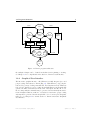
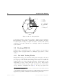
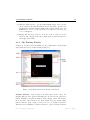
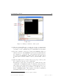
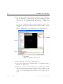
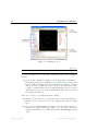
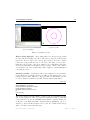
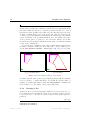
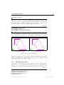
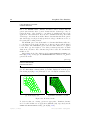
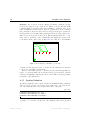
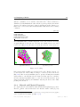
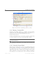
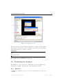
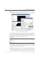
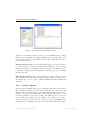
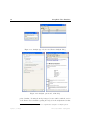
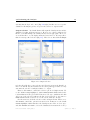
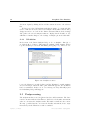
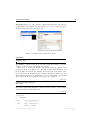
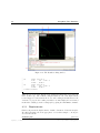
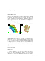
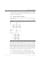
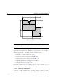
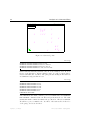
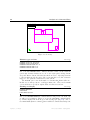
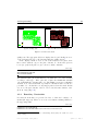
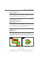
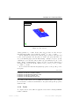
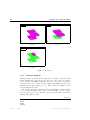
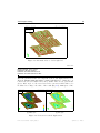
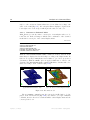
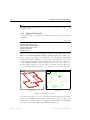
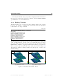
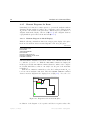
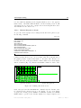
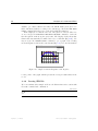
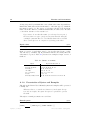
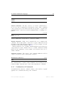
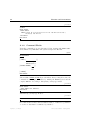
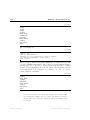
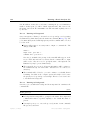
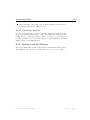
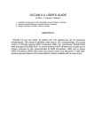
24
Graphical User Interface
LABEL GEOMETRY DIVISIONS
MESHING GENERATE
Due to the MESHING TYPES command, all surfaces will be meshed with the
generic QU8 elements, where ‘generic’ means that the element type only describes the shape of the element, i.e., an eight-node quadrilateral, and not the
application or stress situation. If we use the command menu and point at this
element type, the menu shows all the Diana elements that match the generic
QU8 element type for the previously specified model type. In this case we choose
the CQ24P plate bending element.
The DIVISION option controls the number of elements that iDiana will create,
i.e., the fineness of the mesh. In this case we first specify an explicit division
for a few lines. The PROPAGATE option causes the same division to be applied
for the lines’ opposite neighbors. Note that you must specify twice as much
divisions as you want to have elements along a line because the elements have
midside nodes.
After having checked the divisions via the LABEL GEOMETRY DIVISIONS command [Fig. 2.11b], we may give the MESHING GENERATE command to let iDiana
generate the mesh.
plate.fgc
VIEW MESH
VIEW OPTIONS SHRINK
VIEW HIDDEN SHADE
After generation, the mesh will not be displayed automatically. Therefore we
give the VIEW MESH command which, by default, displays the mesh in green
wire netting style [Fig. 2.12a]. This style does not clearly show unwanted holes.
iDIANA 9.2-08 : TNO Diana BV
11 MAR 2008 09:29:56 mesh.ps
Y
Z
iDIANA 9.2-08 : TNO Diana BV
11 MAR 2008 09:29:56 mesh2.ps
Y
X
Z
(a) default display style
X
(b) shrunken elements & color fill
Figure 2.12: Generated mesh
To check for that, two viewing options are appropriate: ‘shrunken elements’
and ‘color fill’. In this case we apply these simultaneously, respectively via the
SHRINK and HIDDEN SHADE viewing options [Fig. 2.12b].
April 25, 2008 – First ed.
Diana-9.3 User’s Manual – Getting Started