1
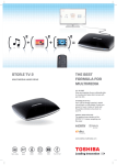
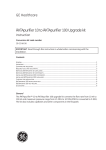
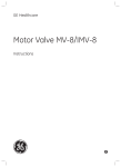
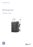
GE Healthcare
Short Instructions 56-0426-00 AO
Flanging/Start Up Kit
Flanging/Start Up Kit (Code No. 19-5079-01, 120 V and
19-5090-01, 230V) is used to flange tubing ends
(0.5–0.8 mm i.d.) so that the tubing is retained inside the
tubing connector. With the flanging kit it is possible to
prepare tubing of any length to fit a specific system.
The Flanging heater is based on a standard soldering iron
with a special tip for flanging of capillary tubings.
Flanges are made by pushing the capillary tubing onto the
heated flanging tip. As the tubing heats up it flares out; the
flanging tip is removed and the tubing is pressed against a
flat, cool surface in order to fix the flange.
Safety
WARNING! Hot-surface. Risk for fire or injury if soldering
tip or element is not handled with care.
WARNING! A fire may result if the appliance is not used
with care, therefore;
- be careful when using the appliance in places where
there are combustibles
- do not apply to the same place for a long time
- do not use in the presence of an explosive atmosphere
Check the packing list to ensure receipt of all necessary
parts.
- be aware that heat may be conducted to combustible
materials
Important user information
- place the appliance on its stand after use and allow it
to cool down
Meaning: Consult the instruction manual to avoid
personal injury or damage to the product or other
equipment.
Meaning: Hot surface. Risk of injury and fire.
- do not leave the appliance unattended when it is
switched on.
Please read the instruction leaflet delivered with the
soldering iron for safe use of the flanging heater.
WARNING!
WARNING! Connect to grounded mains outlet only.
The WARNING! sign is used to call attention to the necessity
to follow an instruction in detail to avoid personal injury.
Be sure not to proceed until the instructions are clearly
understood and all stated conditions are met.
WARNING! Be careful when removing hot cooling collars.
Disconnect the device and wait 15 minutes before
changing the cooling collar!
CAUTION!
Selecting the proper cooling collar
The CAUTION! sign is used to call attention to instructions
or conditions that shall be followed to avoid damage to the
product or other equipment.
Be sure not to proceed until the instructions are clearly
understood and all stated conditions are met.
Mains voltage differences cause temperature variations in
the flanging tool’s tip. With certain voltages the tip becomes
overheated and it melts the tubing.To solve this problem
there are two cooling collars used singly or together for
different mains voltages. Use the appropriate collar or
collars depending on the main voltage from Table 1.
Note
The Note sign is used to indicate information important for
trouble free or optimal use of the product. Should you have
any comments on this instruction, we will be pleased to
receive them at: GE Healthcare Bio-Sciences AB,
SE-751 84 Uppsala, Sweden
WARNING! Be careful when removing hot cooling
collars. Disconnect the device and wait 15 minutes
before changing the cooling collar!
Table 1. Mains voltage and recommended cooling collars.
Technical specification
Mains voltage/volts
Cooling collars
Power requirements
90
110
120
132
198
220
240
264
unnecessary
B (10 mm)
A+B (15 mm)
A+B (15 mm)
unnecessary
A (5 mm)
B (10 mm)
A+B (15 mm)
100–120 V ~ (AC) Model 19-5079-01
220–240 V ~ (AC) Model 19-5090-01
Frequency
50–60 Hz
Power consumption
14 W
Safety standards
This product meets the requirements
of the Low Voltage Directive (LVD)
73/23/EEC through the harmonized
standards EN60335-2-45
How to make a flange
Note: The declaration of conformity is valid for the
instrument when it is:
1. Heat the flanging tool for at least 20 minutes before use.
• used in laboratory locations,
2. Cut with a sharp blade at a 90° angle the appropriate
length of capillary tubing.
• used in the same condition as it was delivered from
GE Healthcare except for alterations described in the
user manual,
3. Thread the tubing through the nipple screw and the
nipple (figure 1).
4. Grasp the tubing with the tubing clamp behind the
nipple. Insert the tubing into the small hole in the black
support on the flanging tool (figure 2), and slide the
nipple up to the support. Reposition the clamp closely
behind the nipple. This ensures that the correct length of
tubing (1.5 mm) protrudes for flanging.
5. Position the tubing end onto the flanging tip. Make
sure the tubing end is parallel to the flat surface of the
flanging tip (figure 3).
6. Push the 1.5 mm of tubing onto the flanging tip
projection and heat for about 5 seconds. Then push hard
until the heated 1.5 mm of protruding tubing flares out
against the flanging tip base (figure 4).
7. Remove the tubing from the flanging tip and press the
newly formed flange against a flat, cool surface (figure 5).
8. Ensure that the flange is not narrower than the tubing by
inserting the flanging tip briefly into the tubing.
9. The flange is now finished (figure 6). It should be
concentric with the tubing bore and slightly smaller than
the diameter of the tubing nipple.
• used as a “stand alone” unit
Maintenance
CAUTION! Only spare parts approved or supplied by
GE Healthcare may be used for maintaining and
servicing of Flanging heater.
The supply cord cannot be replaced. If the cord is damaged
the appliance should be scrapped.
Read the instruction leaflet delivered with the soldering iron
for maintenance of the flanging heater.
Spare parts
CAUTION! Only spare parts approved or supplied by
GE Healthcare may be used for maintaining and
servicing of Flanging heater.
Designation
Code No.
No. per pack
Flanging heater 120 V
19-5080-01
1
or 220 V
19-5098-01
1
Flanging tip
19-7487-01
1
Tubing clamp
19-7844-01
1
Cooling collars (A+B)
19-7825-01
2
Accessories
2
Short Instructions 56-0426-00 AO
Designation
Code No.
No per pack
Capillary tubing
(o.d. 1.8 mm, i.d. 0.5 mm)
19-7477-01
2m
Tubing (o.d. 1.7 mm,
i.d. 1.1 mm)
19-0041-01
5m
Tubing connectors
19-7476-01
5
Wrench
19-7481-01
1
Troubleshooting
Problem
Solution
1. Flange is uneven
Center the flanging tip in the tubing bore.
Heat the tubing for 5 seconds, no longer. Excessive heating could
cause the tubing to melt unevenly.
Make sure the tubing has been cleanly cut to a 90° angle.
2. Diameter of flange is too small
When heating the tubing be sure the entire 1.5 mm of tubing is on
the flanging tip projection. Heat the flanging tool for at least 20
minutes before use.
3. Tubing end does not start easily onto the flanging tip
Heat the flanging tool for at least 20 minutes before use.
Make sure the tubing has been cleanly cut to a 90° angle.
4. Flange rolls back on itself
The correct length of tubing protuberance is important; it should
be 1.5 mm.
5. Tubing protuberance bends and collapses when pushed
onto flanging tip
Measure tubing protuberance (see solution no. 4).
Flange
Nipple screw
Nipple
Tubing
Fig 1. Nipple screw and nipple on tubing.
Fig 3. Tubing end parallel with flanging
tool surface.
Fig 5. Pressing the warm flange against a cool, flat surface.
Fig 2. Measuring the tubing protuberance.
Fig 4. Tubing end pushed against the flat surface of the flanging tip.
Fig 6. Completed tubing flange.
Short Instructions 56-0426-00 AO
3
www.gehealthcare.com
GE Healthcare Bio-Sciences AB
Bjorkgatan 30
751 84 Uppsala
Sweden
GE, imagination at work and GE monogram are trademarks of General
Electric Company
© 2006 General Electric Company – All rights reserved.
All goods and services are sold subject to the terms and conditions
of sale of the company within GE Healthcare which supplies them.
A copy of these terms and conditions is available on request.
Contact your local GE Healthcare representative for the most current
information.
GE Healthcare Bio-Sciences AB
Bjorkgatan 30, 751 84 Uppsala, Sweden
GE Healthcare Europe GmbH
Munzinger Strasse 5, D-79111 Freiburg, Germany
GE Healthcare UK Limited
Amersham Place, Little Chalfont, Buckinghamshire, HP7 9NA, UK
GE Healthcare Bio-Sciences Corp.
800 Centennial Avenue, P.O. Box 1327, Piscataway, NJ 08855-1327, USA
GE Healthcare Bio-Sciences KK
Sanken Bldg. 3-25-1, Hyakunincho Shinjuku-ku, Tokyo 169-0073, Japan
Elanders Östervåla 2006
Asia Pacific Tel: +85 65 62751830 Fax: +85 65 62751829 • Australasia Tel: +61 2 8820 8299 Fax: +61 2 8820 8200 • Austria Tel: 01 /57606 1613 Fax: 01 /57606 1614 • Belgium Tel: 0800 73 890 Fax: 02 416 8206 • Canada Tel: 1 800 463 5800
Fax: 1 800 567 1008 • Central, East, & South East Europe Tel: +43 1 972 720 Fax: +43 1 972 722 750 • Denmark Tel: +45 70 25 24 50 Fax: +45 45 16 2424 • Eire Tel: 1 800 709992 Fax +44 1494 542010 • Finland & Baltics Tel: +358 9 512 3940
Fax: +358 9 512 39439 • France Tel: 01 69 35 67 00 Fax: 01 69 41 98 77 • Germany Tel: 0800 9080 711 Fax: 0800 9080 712 • Greater China Tel: +852 2100 6300 Fax: +852 2100 6338 • Italy Tel: 02 26001 320 Fax: 02 26001 399 • Japan
Tel: 81 3 5331 9336 Fax: 81 3 5331 9370 • Korea Tel: 82 2 6201 3700 Fax: 82 2 6201 3803 • Latin America Tel: +55 11 3933 7300 Fax: +55 11 3933 7304 • Middle East & Africa Tel: +30 210 96 00 687 Fax: +30 210 96 00 693 • Netherlands
Tel: 0800-82 82 82 1 Fax: 0800-82 82 82 4 • Norway Tel: +47 815 65 777 Fax: +47 815 65 666 • Portugal Tel: 21 417 7035 Fax: 21 417 3184 • Russia & other C.I.S. & N.I.S Tel: +7 495 956 5177 Fax: +7 495 956 5176 • Spain Tel: 902 11 72 65
Fax: 935 94 49 65 • Sweden Tel: 018 612 1900 Fax: 018 612 1910 • Switzerland Tel: 0848 8028 10 Fax: 0848 8028 11 • UK Tel: 0800 515 313 Fax: 0800 616 927 • USA Tel: +1 800 526 3593 Fax: +1 877 295 8102
imagination at work
56-0426-00 AO 12/2006