1
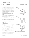
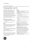
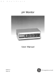
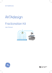
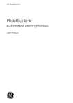
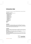
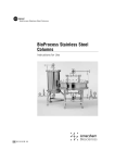
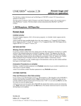
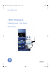
GE Healthcare
Motor Valve MV-8/IMV-8
Instructions
Contents
1. Introduction
3
2. Unpacking
3
3. General Description
4
4. Installation
5
5. Operation
6
6. Applications
2
8
7. Valve maintenance and repair
11
8. Remote connection
12
9. Spare parts and accessories
13
Instructions 56-1153-37 Edition AD
1. Introduction
Motor Valves MV-8 (Code No. 19-7520-01) and IMV-8
(Code No. 18-4586-01) are motorized valves for automatic selection of
columns, solvents and samples, and for fraction collection. The valves have
eight different positions. Each position connects a central port with one of
the eight peripheral ports (Fig 1). The Motor Valve MV-8/IMV-8 is controlled
from the Liquid Chromatography Controller LCC-500, LCC-500 Plus,
LCC-500 CI (Computer Interface) or LCC-501 Plus, all of which can control up
to six motorized valves MV-8/IMV-8 or MV-7/IMV-7. (Motor Valves
MV-7/IMV-7 are automatic injection valves.) The valves can also be
controlled from controlling software such as FPLCdirector™ or UNICORN™.
The main different between MV-8 and IMV-8 is the diameter of the flow
channels. The diameter of the flow channels for MV-8 is 0.6mm and for
IMV-8 is 1.2 mm, which allows higher flow rates at lower back pressure.
MV-8 is normally used in FPLC™System. IMV-8 is normally recommended for
BioPilot™System but can also be used in FPLC System.
8
1
2
7
Peripheral ports
3
6
5
4
Central port
Fig 1. Valve position 1 in a Motor Valve MV-8/IMV-8.
In this manual the LCC-500, LCC-500 Plus, LCC-501 CI and LCC-501 Plus will
be referred to as the controller. Only when differences appear will specific
names be used.
2. Unpacking
Please check delivery against the packing list.
Instructions 56-1153-37 Edition AD
3
3. General Description
3.1
Functional design
The Motor Valve MV-8/IMV-8 consists of two main parts: the housing
which encloses the motor and the electronics, and the valve body with a
central core. The central core rotates 360° inside the valve body. As the
core in turned by the motor, the central port on the bottom of the valve is
connected to one of the peripheral ports 1–8, allowing a clear liquid path.
The peripheral port locations are marked on the valve body directly above
each port. Valve switching is controlled from the controller by reading the
actual position of the valve core by means of signals from a code plate
within the valve housing.
The programmed commands from the controller cause the motor to run
until the valve has reached the desired position.
3.2
Specifications
Motorized 8-position rotary valve used as column, solvent and sample
selection valve or for fraction collection.
MV-8
IMV-8
Maximum operating pressure:
5 MPa (50 bar, 710 psi)
2 MPa (20 bar, 285 psi)
Back pressure at 1000 ml/hr:
0.02 MPa (0.2 bar, 2.8 psi)
–
Back pressure at 6000 ml/h:
–
0.02 MPa (0.2 bar,
2.8 psi)
Wetted material:
PEEK + 20% PTFE
PEEK + 20% PTFE
Angle of rotation:
360°
360°
Dead volume:
1 μl
10 μl
Internal volume of flow channel
between inlet and outlet:
7.4 μl
30 μl
Diameter of flow channel:
0.6 mm
1.2 mm
Motor:
24 V DC
24 V DC
Connector:
D-type, 9 pin on cable
D-type, 9 pin on cable
3.3
Chemical resistance
The valve body in contact with the solvent is made of PEEK and PEEK
+ 20% PTFE. This is resistant to organic solvents and salt buffers commonly
used in a biochemical laboratory. The valve can be used in a pH range of
2-13. If very strong acids (pH <2) or bases (pH >13) are used, the valve
should be rinsed immediately afterwards.
4
Instructions 56-1153-37 Edition AD
Fig 2. Motor Valve MV-8 mounted onto a chromatography rack.
4. Installation
4.1
Mounting the MV-8/IMV-8
The valves are fixed in place by screwing the support rod into the valve
body and attaching the road to a laboratory rack. Mount the valve so the
valve body is facing down (Fig. 2) When mounting valves into an automated
FPLC System, it is recommended to use the Chromatography Rack
(Code No. 18-1031-75). The chromatography rack is supplied with a number
of laboratory rods and clamps which makes the mounting of valves and
other accessories simple and convenient. To mount the valve in the BioPilot
System, please refer to the BioPilot System User Manual.
4.2
Tubing connection
A tubing connection consists of three parts: flanged tubing, nipple and
nipple screw. (Fig 3). All parts necessary for the tubing connection with
instructions for use are supplied in the Flanging/Start-up Kit
(120 V, Code No. 19-5079-01 or 220 V, Code No. 19-5090-01) and in the
Flanging/Start-up Kit for BioPilot (120 V, Code No. 18-4603-70 or 220 V,
Code No. 18-4603-71) is necessary. If you are using tubing other than that
supplied, the flange should have a flat, smooth surface and a diameter of
approx. 3 mm. When connecting the tubing to the valve ports, finger tighten
the tubing connectors into the valve body and the turn them a further
45° with the plastic wrench supplied.
Note: Do not use standard wrenches to tighten the tubing connectors. Do
not overtighten the tubing connectors, they are designed to seal up
to 100 bars when flanged properly. If the connector leaks after it has
been tightened with the plastic wrench, check the flange and make a
new one if needed.
Instructions 56-1153-37 Edition AD
5
Flange
Nipple screw
ca 3mm
Nipple
Tubing
Fig 3. Tubing connection.
4.3
Connection to the controller
Connect the valve to the controller by plugging the D-SUB connector into
one of the sockets on the rear panel if the controller marked VALVE 1–6.
4.4
Valve position guide
Attach the self-adhesive sticker which is supplied with the valve to the valve
housing (see Fig 2). It provides a handy reference to the connection scheme.
5. Operation
5.1
Programming
Valve switching is controlled from the controller or from controlling software
either by manual settings or via programmed methods. During a running
method, a valve is activated at a certain programmed time or volume or
by the monitor signal, i.e. when the monitor signal passes a programmed
threshold.
Allowed positions for the Motor Valve MV-8/IMV-8 are 1 to 8. These numbers
correspond to the eight numbered positions on the valve body. The home
position for the valve is always port 1. If the valve has not been activated
manually or within a programmed method the valve is in its home position.
6
Instructions 56-1153-37 Edition AD
Connect to
Connect to
Columns
Top
Bottom
Port 8
Mono Q®
Port 8
Port 7
®
Mono S
Port 7
Port 6
Mono P®
Port 6
Port 5
Superose® 12
Phenyl Superose
Port 4
Port 3
Port 4
®
Sephadex G-25
Port 3
®
Protein A Superose
Port 2
Port 2
®
Port 1
8
Port 5
®
Sephacryl S-300 HR
1
Port 1
1
8
7
2
7
2
6
3
6
3
4
5
solvent from pump
MV-8/IMV-8
5
4
to detector
MV-8/IMV-8
Fig 4. Two MV-8/IMV-8 valves used for column selection.
There are two functions which are used when controlling the valves from the
controller, VALVE.POS and STP VALVE.
5.2
Function VALVE POS.
To activate a valve MV-8/IMV-8, enter the valve number corresponding
to the socket number on the rear panel of the controller and the position
number. For example, when programming a valve connected to the socket
VALVE 2 to switch to position 5, enter VALVE POS. 2.5. When selecting a new
position, the valve core travels the shortest distance to the next position,
thereby minimizing flow restriction. For example, if a valve is in position
2 and the next setting is to position 7 the valve core moves counterclockwise.
5.3
Function STP VALVE
With this function the MV-8/IMV-8 can be made to step forward (clockwise)
to the next valve position. If valve 5 is in position 3 and the function
STP VALVE 5 is executed the valve steps forward to position 4.
The controller remembers the last position reached by the STP VALVE
function, even if the VALVE.POS function is used between. Examples of how
this feature is used in multiple sample injections and fraction collection are
described in Section 6, Applications.
Instructions 56-1153-37 Edition AD
7
For further information about valve control, consult the User Manual for
respective controller.
1
Pump
S1
S8
Column
S7
7
MV-7/IMV-7
6
S2
2
3
MV-8/IMV-8
S6
4
5
S3
S4
S5
Peristaltic
Pump P-1
Valve 1
Valve 2
1
8
Pump 7
MV-7/IMV-7
2
3
6
5
4
Valve 3
1
8
2
7
6
MV-8/IMV-8
5
4
1
8
3
2
7
6
MV-8/IMV-8
5
3
4
Peristaltic
Pump P-1
Fig 5. One or two MV-8/IMV-8 valves used with an MV-7/IMV-7 valve for automatic
sample injection.
6. Applications
Several examples of the use of the MV-8/IMV-8 as a selection valve are
given below. When used in this manner, the MV-8/IMV-8 condenses
laboratory equipment into less physical space and saves time with faster,
more efficient change-over of columns, pumps, detectors, solvents or
samples.
6.1
Column selection
In Figure 4, two MV-8/IMV-8 valves are used to connect eight different
columns to a single pump and detector. Every time a position is changed
with valve A, the corresponding change must be made with valve B to have
a clear liquid path from the pump to the detector.
Note: Do not mount the valve with the valve body facing up.
8
Instructions 56-1153-37 Edition AD
6.2
Multiple sample injection
Together with the motorized injection valve MV-7(IMV-7, one MV-8/IMV-8
can be used for automatic sample injection of up to 8 samples. With two
MV-8/IMV-8 valves, the number of samples can be increased to 15 (fig 5).
If rinsing is required between sample injections, use the tube in position 1 for
the rinse eluent as described below.
1. Valve 3 (MV-8/IMV-8) in position 1, rinse (Fig 6a).
2. By executing the function STP VALVE 3 the valve moves to port 2 and
injects the sample located there (Fig 6b).
3. By executing the function VALVE POS 3.1 the valve returns to position
1 (rinse) and performs a rinse cycle (Fig 6c).
1 Rinse
8
Valve 3
7
2
6
3
5
1 Rinse
8
Valve 3
7
3
6
4
to MV-7/IMV-7
Fig 6a. Valve position 1
7
Fig 6b. STP VALVE 3
1 Rinse
Valve 3
6
5
4
5
to MV-7/IMV-7
8
2
3
6
4
1 Rinse
8
7
to MV-7/IMV-7
2
Valve 3
2
3
4
5
to MV-7/IMV-7
Fig 6. Two MV-8/IMV-8 valves used in combination with an MV-7/IMV-7 valve for
automatic sample injection of up to 8 or 15 samples.
4. At the next STP VALVE 3 command, the control unit remembers that the
previously injected sample was located at port 2 and advances directly
to position 3 (Fig 6d).
5. The STP VALVE function is reset by the instruction VALVE.POS 3.8 or at the
end of the method. The next time STP VALVE is executed after a reset the
valve will move to position 2.
For further information, see the User Manual for respective controller.
6.3
Solvent selection
The Motor Valve MV-8/IMV-8 can be used for method development in liquid
chromatography. If the valve is used as shown in Figure 7, up to eight runs
with different solvents can be performed automatically since the controller
allow automatic solvent changeover.
Instructions 56-1153-37 Edition AD
9
Note: With the MV-8/IMV-8 connected before the pump P-500, you should
use tubing with large inner diameter to avoid cavitation, e.g. tubing
with 1.1 mm i.d. When connected before Pump P-6000, 1.9 mm i.d.
tubing should be used.
Buffer E
Buffer A
8
Buffer F
1
Buffer B
7
2
6
3
Buffer C
Buffer G
Buffer H
5
4
Buffer D
to pump
Fig 7. The MV-8/IMV-8 used for solvent selection.
6.4
Fraction collection
The MV-8/IMV-8 can also be used to collect fractions from an effluent
stream. This application is illustrated in Figure 8.
When collection fractions it is possible to program a delay time or volume in
the controller corresponding to the time or volume necessary for the liquid
in the cell of the monitor to reach the tubing outlet. By using the commands
PS CALL and PE CALL you can collect only the peaks. (The corresponding
commands to PS CALL and PE CALL in UNICORN is found under the “Watch”
instruction). Then position 1 can function as a drain or waste port in the
same way as rinsing is done in sample injection (Section 6.2), allowing
effluent between peaks to be diverted to a separate container (Fig 8). For
further information, see the Applications section in the User Manual for your
controller.
10
Instructions 56-1153-37 Edition AD
Column
Monitor
Fraction 8
Waste
1
8
Fraction 7
7
2
Fraction 2
Fraction 6
6
3
Fraction 3
Fraction 5
5
4
Fraction 4
Fig 8. The MV-8/IMV-8 used for fraction collecting.
7. Valve maintenance and repair
The valve can be cleaned either by pumping solvents through it, or if that
is not efficient enough, by disassembling the valve and placing the channel
plate and the distributing plate in an ultrasonicator. Suitable cleaning
solvents are water, ethanol, 75% acetic acid, 0.2 M NaOH and detergents.
When using cleaning agents other than water, always rinse the valve with
water as the final step. Disassembly, see Figure 9.
1. Set the valve to position 1 before disconnection it from the control unit.
2. Remove the four Allen screws on the bottom of the valve. Loosen each
one equally in turn until the bottom plate comes off parallel to the valve
body.
3. Slide these screws out with the stainless steel plate.
4. Remove the distributing plate containing the 8 ports.
5. Remove the channel plate.
Instructions 56-1153-37 Edition AD
11
6. Place the channel plate and the distributing plate, (Fig 9) into an ultrasonicator with an appropriate wash solution. These two parts are also
the only parts likely to need replacement. They are supplied together as
spare parts in the Valve V-8 kit (Code No. 19-7806-01)/Valve Kit IMV-8
(Code No. 18-4595-01). Replace these plates when worn.
Valve kit V-8/Valve kit IMV-8
Valve axel
Distruting plate
Central port
Channel plate
Allen screw
Stainless steel plate
Fig 9. Disassembled Motor Valve MV-8/IMV-8.
Note: When reassembling the valve be sure that the channel plate connects
the central port with the peripheral port, number 1. The four Allen
screws on the bottom of the valve should be tightened equally in turn
until the bottom plate is fixed to the valve body.
8. Remote connection
The following section describes the function and activation state of the pins
in the remote connections.
12
Pin
Active
voltage
1
+24 V
Supplies power to the motor and relay. For power
consumption see pins 2 and 6.
2
0
Controls the valve rotation (Sink min. 30 mA, for clockwise
rotation.)
3
0–1.5 V
Indicates the valve position match. When active (in position)
the valve position can be read on pins 7, 8 and 9 (address
pins).
4
–
Signal ground voltage reference for the signals listed in this
table.
5
+5 V
Supplies power to the LEDs in the valve. Min. 80 mA.
6
0
Controls the start/stop function of the motor. Sink min. 1 A to
start, then approx. 0.3 A while running. Short circuit to pin
1 to stop.
7
min. 3 V
Indicates the valve address BIT 2. See also table below.
8
min. 3 V
Indicates the valve address BIT 1. See also table below.
9
min. 3 V
Indicates the valve address BIT 0. See also table below.
Function
Instructions 56-1153-37 Edition AD
Codes for the 8 valve positions are shown in the table below.
Note: The motor Valve MV-8/IMV-8 is designed to be controlled by the
controller. If the MV-8/IMV-8 is controlled from other equipment (e.g. a
microprocessor) a 10kΩ pull-up resistor to +5 V must be connected to
pins 3, 7, 8 and 9 of the 9 pin D-SUB connector of the MV-8/IMV-8.
Position
BIT 2
Address
BIT 1
BIT 0
Position
match
1
0
0
1
0
2
0
1
0
0
3
0
1
1
0
4
1
0
0
0
5
1
0
1
0
6
1
1
0
0
7
1
1
1
0
8
0
0
0
0
1 = 3-5
0 = 0-1.5 V
9. Spare parts and accessories
Accessories MV-8
Designation
No.
Code No.
per pack
Capillary tubing
(o.d. 1.8 mm, i.d 0.5 mm)
2m
19-7477-01
5
19-7476-01
1
1
19-5079-01
19-5090-01
1
19-7510-01
Designation
No.
Code No.
per pack
Valve V-8 kit
1
19-7806-01
Tubing connectors
Flanging/Start Up kit,
Motor Valve MV-7
120 V
220 V
Spare Parts MV-8
Instructions 56-1153-37 Edition AD
13
Accessories IMV-8
Designation
No.
Code No.
per pack
Tubing (i.d. 1.2 mm,
o.d. 1.8 mm)
2m
19-4370-01
Tubing connectors 1.8
5
19-7476-01
Tubing (i.d 1.9 mm,
o.d 2.7 mm)
2m
18-8207-01
Tubing connectors 2.7
5
18-4652-01
Flanging Tip Kit i.d. 1.2
1
18-4597-01
Flanging Tip Kit i.d. 1.9
1
18-4596-01
Flanging/start up Kit
for BioPilot 120 V
18-4603-70
Flanging/start up Kit
for BioPilot 220 V
18-4603-71
Motor Valve IMV-7
18-4585-01
Superloop 150 mI
19-7850-01
Spare Parts MV-8
14
Designation
No.
Code No.
per pack
Valve Kit IMV-8
1
18-4595-01
Instructions 56-1153-37 Edition AD
Instructions 56-1153-37 Edition AD
15
www.gehealthcare.com
GE Healthcare Bio-Sciences AB
Björkgatan 30
751 84 Uppsala
Sweden
Sepharose is a trademark of GE Healthcare companies.
GE, imagination at work and GE monogram are trademarks of General
Electric Company.
All goods and services are sold subject to the terms and conditions of
sale of the company within GE Healthcare which supplies them.
GE Healthcare reserves the right, subject to any regulatory and
contractual approval, if required, to make changes in specifications
and features shown herein, or discontinue the product described at
any time without notice or obligation. Contact your local GE Healthcare
representative for the most current information.
© 2006 General Electric Company – All rights reserved.
GE Healthcare Bio-Sciences AB, a General Electric Company.
GE Healthcare Europe GmbH
Munzinger Strasse 5, D-79111 Freiburg, Germany
GE Healthcare UK Ltd
Amersham Place, Little Chalfont, Buckinghamshire, HP7 9NA, UK
GE Healthcare Bio-Sciences Corp
800 Centennial Avenue, P.O. Box 1327,
Piscataway, NJ 08855-1327, USA
Asia Pacific Tel: +85 65 62751830 Fax: +85 65 62751829 • Australasia Tel: +61 2 8820 8299 Fax: +61 2 8820 8200 • Austria Tel: 01 /57606 1613 Fax: 01 /57606 1614 • Belgium Tel: 0800 73 890
Fax: 02 416 8206 • Canada Tel: 1 800 463 5800 Fax: 1 800 567 1008 • Central, East, & South East Europe Tel: +43 1 972 720 Fax: +43 1 972 722 750 • Denmark Tel: +45 70 25 24 50 Fax: +45 45 16 2424 •
Eire Tel: 1 800 709992 Fax +44 1494 542010 • Finland & Baltics Tel: +358 9 512 3940 Fax: +358 9 512 39439 • France Tel: 01 69 35 67 00 Fax: 01 69 41 98 77 • Germany Tel: 0800 9080 711
Fax: 0800 9080 712 • Greater China Tel: +852 2100 6300 Fax: +852 2100 6338 • Italy Tel: 02 26001 320 Fax: 02 26001 399 • Japan Tel: 81 3 5331 9336 Fax: 81 3 5331 9370 • Korea Tel: 82 2 6201 3700
Fax: 82 2 6201 3803 • Latin America Tel: +55 11 3933 7300 Fax: +55 11 3933 7304 • Middle East & Africa Tel: +30 210 96 00 687 Fax: +30 210 96 00 693 • Netherlands Tel: 0800-82 82 82 1
Fax: 0800-82 82 82 4 • Norway Tel: +47 815 65 777 Fax: +47 815 65 666 • Portugal Tel: 21 417 7035 Fax: 21 417 3184 • Russia & other C.I.S. & N.I.S Tel: +7 495 956 5177 Fax: +7 495 956 5176 •
Spain Tel: 902 11 72 65 Fax: 935 94 49 65 • Sweden Tel: 018 612 1900 Fax: 018 612 1910 • Switzerland Tel: 0848 8028 10 Fax: 0848 8028 11 • UK Tel: 0800 515 313 Fax: 0800 616 927 • USA
Tel: +1 800 526 3593 Fax: +1 877 295 8102
56-1153-37 AD 12/2006
Elanders Östervåla 2006
GE Healthcare Bio-Sciences KK
Sanken Bldg. 3-25-1, Hyakunincho
Shinjuku-ku, Tokyo 169-0073, Japan