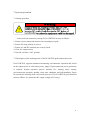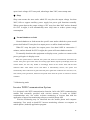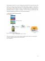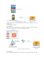
1
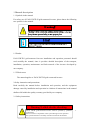
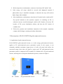
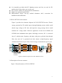
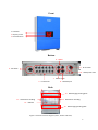
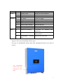
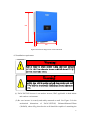
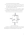
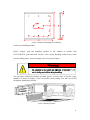
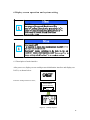
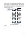
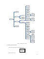
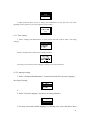
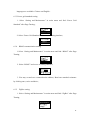
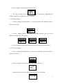
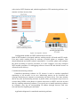
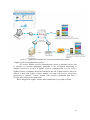
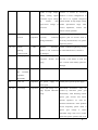
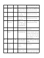
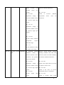
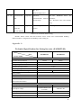
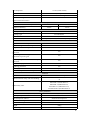
EA30-35KTLSI PV Grid-connected Inverter User Manual GUANGDONG EAST POWER CO.LTD I Dear customer, thanks for selecting EA3KLPV II and EA5KLPV II photovoltaic (PV) grid-connected inverter products developed by Guangdong East Power Co., Ltd., we sincerely hope our products can meet your needs, and look forward to more advice on product performance and function. We will continue to improve the product quality. Read through the manual before use the product. The manual should be stored together with other materials regarding product module and kept accessible to relevant personnel. The manual, and the pictures, labels and symbols herein shall be the property of Guangdong East Power Co., Ltd. No personnel out of the company is permitted to reproduce the manual in public, in full or part, without the written permission from the company. The manual will be constantly updated and revised, and there may be inconsistency or wrong description, the user shall refer to the purchased product in kind, may download from www.eastups.com or seek for the manual of latest version from marketing channels. II Contents 1 Manual description..................................................................................................... 1 1.1 Symbols in the manual..................................................................................... 1 1.2 Reader............................................................................................................... 1 1.3 Effectiveness..................................................................................................... 1 2 Safety instruction and precautions..................................................................... 1 2.1 Safety instructions............................................................................................ 1 2.2 Precautions....................................................................................................... 2 3 Description of EA30‐35KTLSI grid‐connected inverter................................................3 3.1 Application of grid‐connected inverter............................................................3 3.2 Features of EA30‐35KTLSI grid‐connected inverter.........................................4 3.3EA30‐35KTLSI circuit structure.......................................................................... 5 3.4 Description of inverter structure..................................................................... 5 4 Installation...................................................................................................................8 4.1 Inspection before installation.......................................................................... 8 4.2 Overall dimensions........................................................................................... 8 4.3 Installation requirement.................................................................................. 9 4.4 Inverter handling method.............................................................................. 11 5 System wiring............................................................................................................ 12 5.1 Requirement for connection cables...............................................................12 5.2 Cable and wiring method............................................................................... 13 5.2.1。PV input wire manufacturing and connector assembly.....................13 5.2.2 AC output line and ground wire manufacturing and AC output connector assembly, AC output line connection........................................... 14 5.2.3 Prepare RS484 communication line and Assemble RJ45 terminal....... 16 5.2.4 USB terminal wire connection........................................................... 17 6 Display screen operation and system setting............................................................18 6.1 Description of main interface........................................................................ 18 6.2 Menu...............................................................................................................19 6.3 Setting and maintenance............................................................................... 20 6.3.1 Time setting...........................................................................................21 6.3.2 Language setting................................................................................... 21 6.3.3 Power grid standard setting.................................................................. 22 6.3.4 RS485 communication setting........................................................... 22 6.3.5 ZigBee setting.....................................................................................22 6.3.6 Earning setting.......................................................................................23 6.3.7 Password change...................................................................................23 6.3.8 USB function.......................................................................................24 III 6.3.9 Restore factory default.......................................................................24 6.3.10 View product information................................................................... 25 6.4 Startup & Shutdown...............................................................................................25 6.5 View warning information......................................................................................25 7 System operation...................................................................................................... 27 7.1 Startup procedure.......................................................................................... 27 7.2 Description of the working mode of EA30‐35KTLSI grid‐connected inverter ...............................................................................................................................27 7.4 Monitoring mode............................................................................................29 8 Fault handling............................................................................................................34 Appendix A................................................................................................................... 39 Technical Specification for String Inverter (EA30KTLSI)............................................... 39 1 Quality warranty.............................................................................................41 2 Contact us.......................................................................................................... 41 IV 1 Manual description 1.1 Symbols in the manual For safety use of EA30-35KTLSI grid-connected inverter, please know the following two symbols in the manual. 1.2 Reader EA30-35KTLS grid-connected inverter installation and operation personnel should read carefully the manual, since it provides detailed description of the transport, installation, operation, maintenance and fault removal of the inverter developed by our company. 1.3 Effectiveness The manual applies to EA30-35KTLS grid-connected inverter. 2 Safety instruction and precautions Read carefully the manual before installation and operation, and the equipment damage caused by installation and operation in violation of instructions in the manual shall not fall within the quality warranty provided by our company. 2.1 Safety instructions Warning! Lethal electric shocking. ! EA30- 35KTL grid-connected inverter shall be operated by qualified professional. Never touch live components in PV system during inverter operation. Pay special attention to all safety instructions listed in this manual. 1 2.2 Precautions Inverter should be correctly handled, stored, assembled, installed, operated and maintained. All operations and wiring should be performed by professional electric or mechanical engineer so as to ensure all electrical installations compliant with relevant standard. To ensure safe operation, it is required to provide correct earthing and necessary short-circuit protection. 2 Before inspection or maintenance, ensure no electricity at DC and AC side. Solar energy cell arrays should be covered with lightproof material if photovoltaic array is installed in daylight, or otherwise the array will result in high voltage under sunlight. After installation or maintenance, shut down AC breaker before switch on DC. Pay special attention to the operation sequence of switching on DC, or otherwise inverter would be damaged: switch on DC breaker of inverter, DC breaker of DC power distribution cabinet, and then the DC breaker of combiner box. Follow the operation and installation instruction in the manual, completely comply with all danger, warning and safety information. 3 Description of EA30-35KTLSI grid-connected inverter 3.1 Application of grid-connected inverter EA30-35KTLSI grid-connected inverter, as a solar energy grid-connected inverter, applies to PV grid-connected power generation system. In the system, it con constantly maintain maximum output power of solar cell panel and deliver the converted energy from solar cell panel to power grid. PV grid-connected power generation system is composed of PV module, PV combiner box, PV grid-connected inverter, metering device and power distribution system, as shown in Figure 1. PV module Metering device Power grid PV grid-connected inverter 3 Figure 1 PV grid-connected power generation system 3.2 Features of EA30-35KTLSI grid-connected inverter z z z z z z Non-isolated transformer provides conversion efficiency up to 98.7% and European efficiency 98.4%; Three-route MPPT, acquiring generated energy from battery pack in shadow as much as possible; Wide MPPT voltage range (320~900V) and longer daily power generation time; Intelligent MPPT algorithm, maximum power point tracing free from influence of illumination change; Precision recognition technology for power change guarantees accurate and stable static MPPT; Wide working temperature range -25 ℃ —60 ℃ , support continuous power generation under full-load in high temperature environment. High reliability z Membrane capacitor is designed with long service life, and the equipment is designed with 25-year service life; z Natural radiation, water-roof, and high resistance to dust and salt-spray corrosion; z Active+ passive island protection, grid-connected relay redundancy disconnection protection, safe and reliable; z Multi-layer overcurrent, overvoltage, over temperature and short-circuit protection for software and hardware; z Up to 6-route serial fault detection and rapid serial fault location. Advanced control technology z Three-level SPWM and SVPWM dual modulation and natural smooth switchover; z Self-adaption control, adaptive to severe week power grid environment; z Current harmonic compensation, grid-connection current harmonic〈1%; z Support active and reactive power gird regulation and night SVG function; z Low-voltage (no-voltage) fault ride-through function. User-friendly and flexible z Multi-language LCD display screen allows for flexible setting of operation parameters; 4 z z z z It is internally provided with DC lightning arrester and fuse, no need for DC combiner box, helps reduce user system cost; DC on-off air switch, safe and convenient maintenance; Outdoor use protection grade IP 65; Wall-mounted design, one-step molded aluminum shell, convenient for installation and maintenance. 3.3EA30-35KTLSI circuit structure Figure 2 provides the schematic diagram for EA30-35KTLSI inverter. Electric energy generated by PV module passes through lightning arrester which would absorb surge voltage at DC side, and capacitive energy storage device would maintain DC voltage stable. With the application of three-level SPWM and SVPWM dual modulation three-phase full-bridge inversion, DC is converted into AC with the same frequency and phase with power grid and, then through filter, sine wave AC is generated and, after subject to high-frequency signal conducted interference by AC filter, electric energy is transmitted to power grid. Figure 2 Schematic diagram for EA30-35KTLSI inverter 3.4 Description of inverter structure Figure 3 External structure of EA30-35KTLSI 5 Front 1. Indicator 2. Display screen 3. Knock etection Bottom 6、RS485 9、AC terminal 4、DC switch 10、Waterproof valve 7、USB terminal 5、PV terminal 8、Network port Back 13、Wall‐hanging backing plate 11、Handrail for handling 11、Handrail for handling 12、Radiator 13、Wall‐hanging backing plate Figure 3 External structure diagram (Front, bottom and back) 6 Front Bottom Back No. 1 2 3 4 5 6 7 8 9 10 11 Name Display screen Knock detection Indicator DC switch PV terminal RS485 terminal USB terminal Network cable terminal AC terminal Water-proof valve Handrail for handling Description Display inverter parameters Set and view inverter parameters Indicate inverter state Control PV input Connect with PV battery RS485 port USB port Network interface Connect with three-phase AC Waterproof and breathable Convenient for handling and installation Reduce temperature of inverter power device backing Hang inverter onto wall 12 Radiator 13 Wall-hanging plate Figure 1 Appearance description Figure 4 shows the maintainable interior parts. You may see maintainable interior parts after opening the bottom cover plate of inverter. See maintainable interior parts after opening the cover plate 7 5、DC Fan 1、PV DC switch 2、PV DC fuse base 3 、 PV DC lightning4、AC filter arrester Figure 4 Maintainable interior parts No. 1 2 3 Name PV DC switch PV DC fuse base PV DC lightning arrester AC filter DC Fan 4 5 Description Control on/off of PV input Contain breaker, protect battery plate Anti-surge AC output filtering Enhance radiating capacity of radiator Table 2 Description of maintainable parts 4 Installation 4.1 Inspection before installation EA30-35KTLSI grid-connected inverter has been subject to careful testing and detection before delivery, while it may be damaged in transit. In case of any damage, contact with the transport company or directly contact with East and provide photo of the damaged part, we’ll sincerely provide you the best service as soon as possible. 4.2 Overall dimensions See Figure 5 for the mechanical dimensions of EA30-35KTLSI: 580mmx820mmx255mm (WxHxD), about 65kg. 8 820 580 255 Figure Dimensional diagram for EA30-35KTLSI 4.3 Installation requirement (1) EA30-35KTLSI inverter is an outdoor inverter, IP65, applicable in both indoor and outdoor environment. (2) Be sure inverter is securely and stably mounted on wall. See Figure 5 for the mechanical dimensions of EA30-35KTLSI, 580mmx820mmx255mm (WxHxD), about 65kg, therefore the wall should be capable of sustaining the 9 inverter and provided with sufficient space for installation. (3) The space between inverter and surrounding objects shall comply with the following conditions: horizontal space≥200mm; upper space ≥500mm; lower space ≥300mm and front space ≥1000mm (as shown in Figure 6), so as to ensure sufficient installation and radiation space. (4) According to the EMC and noise level, inverter is applicable to industrial environment and should be installed away from living area as far as possible. (5) Vertical installation, or at most backward inclination 15°is recommended. It Should be installed in positive direction, with terminals facing downward. Figure 6 Minimum installation space (6) Securely fix wall plate onto wall with explosion screw, keep inverter upward, align the groove of hanging backing plate with the convex edge of wall plate and then slightly lower it. See the structural diagram for wall plate in Figure 7. 10 Figure 7 Structural diagram for wall plate 4.4 Inverter handling method Please comply with the handling method in the manual to handle with EA30-35KTLSI grid-connected inverter, since wrong handling method may cause inverter falling down, inverter damage and even personal injury. Two operators should keep hands at handle groove on both sides of inverter, grasp handlers, as shown in Figure 8, take out inverter from packing case and carry to the designated installation position. Figure 8 Handling method 11 5 System wiring This chapter would describe the electrical connection between EA30-35KTLSI grid-connected inverter and solar cell array as well as the power grid and its trial operation. Please read carefully the following instructions, warnings and precautions before connection. 5.1 Requirement for connection cables Cable name Cable unit (mm2) PV array DC+ Provide 6-route input, wire diameter no less than 4-6mm2 PV array DC- Provide 6-route input, wire diameter no less than 4-6mm2 Power grid L1 phase Provide single-route input, wire diameter no less than 8-10mm2 Power grid L2 phase Provide single-route input, wire diameter no less than 8-10mm2 Power grid L3 phase Provide single-route input, wire diameter no less than 8-10mm2 Power grid N Wire diameter no less than 8-10mm2 12 Wire diameter no less than 8-10mm2 Ground wire Table 3 Requirement for cables 5.2 Cable and wiring method 5.2.1。PV input wire manufacturing and connector assembly Step 1: Strip about 6mm insulation layer from DC cable to expose copper wire, insert copper wire into metal tube core of connector and clamp it with wire crimper. -pole input terminal and tube core + pole input terminal and tube core Strip cable, insert it into tube core and clamp it with wire crimper. Step 2: 2. Loosen terminal cap and lead cable through the cap. Insert tube core into wire slot until the connection is completed. 13 Step 3: Tighten terminal cap. Step 4: Insert terminals with connected lines into corresponding + and – terminal at the bottom of inverter. 5.2.2 AC output line and ground wire manufacturing and AC output connector assembly, AC output line connection Step 1: Disassemble AC output connector and check accessory for completeness. From left to right: 1. Mating socket; 3. Shell; 3. Seal ring; 4. Sealing cap 14 Step 2: Strip the sheath and insulation layer of appropriate length from AC output cable with wire stripper. Step 3: Lead AC output cable (L1, L2, L3, N, PE) through cable sealing cartridge and sleeve. Step 4: Loosen screws in the jack of matting socket with straight screwdriver, insert cable core into corresponding jack and tighten screws. L1 connecting to 1# jack; L2 connecting to 2# jack; L3 connecting to 3# jack; N line connecting to N jack. PE line connecting to jack. Step 5: Install mating socket on the shell and it is in place when you hear “click”. Tighten sealing cap on the shell. 15 Step 6: Connect AC output connector to bayonet joint at inverter AC output terminal, push it until hear “click”. 5.2.3 Prepare RS484 communication line and Assemble RJ45 terminal Recommended RS485 communication cables: 24AWG outdoor shielded network cable (standard cable, internal resistance less or equivalent to 1.5Ω /10m), shielded twisted pair network cable, outer diameter of 4.5mm~7.5mm (8 cable cores, wire diameter of each 1.00mm~1.07mm). As shown in the structural diagram for waterproof RJ45 terminal, parts from left to right are: 1. Plastic seat; 2. Mating nut; 3. Cable sealing nut (No crystal head and network cable would be provided). Step 1: Strip the insulation layer of appropriate length from shielded network cable with wire stripper. Step 2: Lead shielded network cable through cable sealing nut, mating nut and plastic seat in succession. 16 Step 3: Arrange in sequence shielded network cables with insulating layer stripped and insert into crystal head. No. 1 2 3 4 5 6 7 8 Color White orange Orange White green Blue White blue Green White brown Brown Function RS485A, RS485 differential signal + RS485B, RS485 differential signalPGND RS485A, RS485 differential signal + RS485B, RS485 differential signalPGND PGND PGND Table 4 Definition of network cable connection Step 4: Clamp crystal head with wire crimper, put plastic base on the crystal head with shielded network cable, tighten cable sealing nut. Step 5: Insert crystal head into inverter RS485 port and tighten mating nut. 5.2.4 USB terminal wire connection Our company would not provide USB connection wire that is the general wire. 17 6 Display screen operation and system setting 6.1 Description of main interface After power-on, display screen would present initialization interface and display our LOGO, as shown below: Enter the startup interface 2s later; EASI030KTL System Starting 25% Figure 9 Startup diagram 18 It would enter main interface after startup. Main interface includes 10 pages, displaying respectively the operation state, generated energy, earning, power factor, efficiency, input and output power, active power, reactive power, apparent power, plus or minus the DC voltage, power grid voltage, PV input information such as current, voltage, temperature, as shown below: Figure 10 Description of main interface 6.2 Menu The following figure is the menu operation flow chart. The manual provides only the setting and maintenance for user part. 19 Time Setting Language Grid Standard RS485 Setting System Alarm ZigBee Setting Income Setting Start Start/Stop Currency Type Yield Rate PWD Setting Stop USB App Record Export User Factory Restore Record Clear Engineer Time Setting Main Menu Parameters Language Grid Standard Product Info RS485 Setting ZigBee Setting Income Setting Currency Type Yield Rate PWD Setting USB App Record Export Factory Restore Record Clear Product Info Config Import Config Export FW Upgrade Figure 11 Menu process chart 6.3 Setting and maintenance 1. Enter main menu and select Setting Maintenance; 2. Select ordinary User; 20 3. Input password when access to Setting and Maintenance in the first time and, after inputting correct password, you may complete system setting. 6.3.1 Time setting 1. Select “Setting and Maintenance” in main menu and find “System Time” after Page Turning; 2. Select “System Time” and access to setting interface; 3. You may revise and save time setting by clicking once, twice and thrice. 6.3.2 Language setting 1. Select “Setting and Maintenance” in main menu and find “System Language” after Page Turning; 2、 2. Select “System Language” and access to setting interface; 3. You may select and confirm language by clicking once, twice and thrice; three 21 languages are available: Chinese and English . 6.3.3 Power grid standard setting 1. Select “Setting and Maintenance” in main menu and find “Power Grid Standard” after Page Turning; 2. Select “Power Grid Standard” and access to setting interface; 6.3.4 RS485 communication setting 1. Select “Setting and Maintenance” in main menu and find “RS485” after Page Turning; 2. Select “RS485” and access to setting interface; 3. You may set and save communication address, Baud rate matched resistance by clicking once, twice and thrice; 6.3.5 ZigBee setting 1. Select “Setting and Maintenance” in main menu and find “ZigBee” after Page Turning; 22 2. Select “ZigBee” and access to setting interface; 3. You may set and save communication address, Baud rate, ZigBeeID and Zeigbee channel by clicking once, twice and thrice; 6.3.6 Earning setting 1. Select “Setting and Maintenance” in main menu and find “Earning Setting” after Page Turning; 2. Select “Earning Setting” and access to setting interface, you may select different currencies by turning page; 3. Save setting by double click and you may cancel setting by clicking thrice. 6.3.7 Password change 1. Select “Setting and Maintenance” in main menu and find “Change Password” after Page Turning; 2. Select “Change Password” and access to Change interface; 3. Input new password and confirm it, then the revision is finished. 23 6.3.8 USB function 1. Select “Setting and Maintenance” in main menu and find “USB Function” after Page Turning; 2. Select “USB Function”, access to “Record Export” interface and select “Export”; Record Record Export Export Clear Record Config Import Config Export 3. If U disk is inserted, record would be exported to the disk; 4. If U disk is not inserted, system will prompt user inserting U disk. 5. Select “Delete Record” and confirm it, then the historic record saved in inverter will be deleted. Record Export Clear Record Config Import Config Export 6.3.9 Restore factory default 1. Select “Setting and Maintenance” in main menu and find “Restore Factory Default” after Page Turning; 24 2. Select “Restore Factory Default” and confirm it, all configuration and historic data will be cleared; 6.3.10 View product information 1. Select “About” in main menu interface; 2. It will display firmware version of the current system and Vxxx product model, as well as the cumulative operation time since system power-on. 6.4 Startup & Shutdown 1. Enter main menu by double click on any page in main interface, and select “Startup & Shutdown” by single click; 2. You may select “Startup” or “Shutdown” with double click as required. 6.5 View warning information 1. Enter main menu by double click on any page in main interface, and select “Warning Information” by single click; 25 2. You may check current inverter fault information by double click, and view more information by clicking on “Page Turning”; In case of system fault warning, red LED will flash, or otherwise would not be lighted. 26 7 System operation 7.1 Startup procedure After electrical connection, start up EA30-35KTLSI inverter as follows: 1. Ensure correct connection between inverter and power grid; 2. Ensure PV array polarity is correct; 3. Ensure AC and DC terminals are securely fixed; 4. Close AC output switch; 5. Turn DC switch to “ON” position. 7.2 Description of the working mode of EA30-35KTLSI grid-connected inverter EA30-35KTLSI supports unmanned monitoring and automatic operation and, based on the output power of solar battery array, judges if grid-connection power generation is required. System operation process includes five working states: startup, grid-connection operation, standby, sleep state, shutdown and fault handling. Figure 14 presents the working mode conversion process for EA30-35KTLSI grid-connected inverter (Where Vpv means the DC output voltage of PV array). . 27 Figure 12 Working mode conversion process for inverter Startup Startup refers to the preparatory stage from standby mode to grid-connection operation mode and, under which state, grid-connected inverter would constantly detect if PV module has sufficient energy to generate electricity, namely when PV module has open-circuit voltage up to 320V and solar panel has output power up to 200W, PV grid-connected inverter will convert from startup state to grid-connection operation state. Grid-connection operation Grid-connection operation mode means the mode under which grid-connected inverter will convert DC of PV array into AC to power grid. To optimize the utilization of PV array energy, the system is designed with maximum power point tracking (MPPT) control, namely the system will, regardless of sunshine and temperature, constantly maintain solar cell array output under maximum power state. Standby Standby state means that when PV array output voltage is up to a certain value but fails to comply with startup condition, while parameters such as grid voltage and frequency are within allowable range. Under the mode, inverter will constantly detect 28 open-circuit voltage of PV array and, when larger than 320V, enter startup state. Sleep Sleep state means the state under which PV array has the output voltage less than 200V, fails to support auxiliary power supply but power grid functions normally. When system detects the output voltage of PV array less than 200V and no demand for SVG in night, it will automatically enter sleep state to reduce system energy consumption. Normal shutdown or fault Normal shutdown or fault means the specific state under which the system would protect itself when PV array has low output power or suffers shutdown failure. When PV array has quite low output power less than 100W in consecutive 5 minutes, and no demand for SVG in night, the system will enter shutdown mode. To manually shut down the equipment on display screen, you have to connect with power grid again via display screen. When the system failure is detected, the system will, under no circumstances, disconnect the inverter from power grid. In this state, the warning lights flashes, liquid crystal display shows the current failure, the user may handle it accordingly based on the current fault and the fault treatment table. After failure occurs and failure is automatically remove, the system will automatically detect within 20s if grid-connected power generation conditions are meet and, if so, start normal power generation, otherwise keep fault status until the system is restored to normal condition. 7.4 Monitoring mode Inverter WIFI Communication System It is designed with WIFI communication function, built with WIFI communication module and externally provided with wireless antenna. It needs no RS485 communication wire, can realize real-time monitoring of inverter data with the application of upper host monitoring software or mobile phone APP. Wireless monitoring may be classified into the mobile phone and computer monitoring. User needs to install PV inverter monitoring software on computer or mobile phone (Android) application program. 29 WIFI module built in PV inverter is designed with AP and STA connection mode. The former is a wireless access point, by which mobile phone, computer or other device can connect to WIFI module; the latter is a terminal. WIFI module is connected to router, and user may connect to router via mobile phone or computer and, by monitoring software on phone or computer, view the real-time inverter data. The following diagrams are related to the four connection methods. I. Monitoring at mobile phone terminal Access method 1: Figure 13 Mobile phone- Router- Inverter The access method is one of most common methods and by which, user may log on network by phone and also monitor inverter data. Access method 2: 30 Figure 14 Mobile Phone- Inverter By this access method, user may directly view inverter data via WIFI in case of no wireless router. II. Monitoring via computer Access method 1: User may connect to wireless router via computer, to router via WIFI or network cable, and view inverter data by PV inverter monitoring software. Figure 15 Computer- Router- Inverter Access method 2: User computer is directly connected with PV inverter. The computer must be provided 31 with wireless WIFI function and, with the application of PV monitoring software, can monitor real-time inverter data. Figure 16 Computer- Inverter Configuration method for WIFI module built in inverter: Built-in WIFI module is designed with two working modes: AP mode and STA mode. User may switch working mode by software in mobile phone or computer. User should download and install software smartlink3.6.3 in mobile phone and configure the mode according to specific procedure; as to the computer, user may configure WIFI module parameter via debugging software SecureCRT and default inverter as AP mode before delivery. Centralized monitoring software Centralized monitoring software in PV inverter is used to conduct centralized monitoring of all inverters in an area. Monitoring means can be classified into webpage monitoring on computer or monitoring via phone client. User may monitor data at any time by monitoring software in phone client, and customer may access to wireless data (GPRS) in the phone or connect with router via WIFI, and view inverter data by enabling monitoring software. Users need not to install monitoring software on computer, may log on corresponding IP address through browser, and view relevant data after inputting account name. Application diagram for centralized monitoring software 32 Application diagram for centralized monitoring software ZigBee wireless communication system PV inverter ZigBee wireless communication means to transmit inverter data to collector via wireless equipment, applicable to the centralized monitoring of multiple inverters in an area. If ZigBee wireless communication is to be used, a ZigBee wireless coordinator should be installed at the side of data collector. Since PV inverter is built with ZigBee wireless module, user may only need to set wireless parameters in interface, connect inverter with wireless coordinator and form a wireless network for data transmission. Block diagram for ZigBee wireless data transmission is provided as below: Figure 17 33 Figure 18 ZigBee wireless data transmission is provided as below: 8 Fault handling In case of fault, fault light will be lighted, monitoring panel displays current fault and fault ID, and inverter will determine if to shut down according to warning level. Table 5 provides common fault warnings and handling suggestions. Definition of warning level: Important warning: Inverter will, in case of fault, enter shutdown mode and stop grid-connection power generation. Warning hint: Inverter will still support grid-connection power generation when some parts are out of order. Warning ID Name 101~103 High serial voltage Causes Handling Suggestions Warning Level Important Excessive number of Check if open-circuit voltage higher battery panels in serial than maximum input voltage of 34 results in high output, inverter is caused by excessive finally higher number of series configurations of maximum input voltage PV and if so, regulate configured of serials number to drop output voltage causing inverter than open-circuit voltage of within specification range. After correct adjustment, inverter PV serial. will restore normal operation. 111~113 Serial polarity reversed Serial Important polarity reversely is Check if corresponding positive and connected during installation. negative pole on inverter serial is reversely connected and, if so, please adjust the polarity. 121~123 131 BOOST Hint BOOST lightening lightning arrester is not connected protection fault or damaged. Low input power Hint Check if BOOST lightening arrester is connected and if not, connect it. PV serial is subject to Check if the route of serial is long-term fixation and aging. covered, if the surface is clean and not covered, check battery panel for damage. Important 141 ISO insulation impedance abnormality 201 Power-off Important No power supply for Check power grid for power supply. power grid. 211~216 Overvotlage Important Power grid voltage is too Occasional occurrence may be high, beyond allowable caused by short-term power grid range. abnormality. After detecting normal power grid, inverter will restore normal operation, no need for artificial interference. If the problem occurs frequently, please check if power grid voltage is within allowable range and if not, contact with local power operator and, if so, 35 revise the protection point, subject to approval by local power operator. 221~226 Undervoltage Important Power grid voltage is too Same low, beyond allowable with the suggestions for handling power grid overvoltage. range. 231~236 Overfrequency Important Power grid frequency is Same too high, beyond with the suggestions for handling power grid overvoltage. allowable range. 241~246 Important Underfrequency Power grid frequency is Same too low, with the suggestions beyond handling power grid overvoltage. inverter Same for allowable range. 251~243 Abnormal power Important grid frequency Before grid-connection, power grid detect with the suggestions for handling power grid overvoltage. frequency beyond allowable range. 261 262 Island Power Important grid Important unbalance Abnormally fluctuated Check if power power grid frequency islanding state. Power Occasional grid unbalance beyond allowable range grid is under occurrence may be caused by short-term power grid abnormality. After detecting normal power grid, inverter will restore normal operation, no need for artificial interference. 263 FRT occurrence Hint Power grid voltage is Prompt warning for falling down subject to falling-down voltage, no need for special treatment. 264 Power grid ABC phase Adjust AB or BC or CA two-phase sequence sequence wire connection reversely connected Power grid phase Hint reversely connected 301~331 BOOST fault circuit Important If abnormal external Inverter monitors external working in condition at real time and, after fault BOOST circuit protection removal, restore normal work, no condition results 36 inside inverter, the causes may possible need for artificial interference; include: ID:321~323 ID:301~309 Check Significant change in external condition results if inverter’s temperature sensor BOOST wires are connected. in excessive high input current. ID:311~316 Significant change in external condition results in excessive high input voltage. ID:321~323 Inverter detects BOOST temperature beyond allowable range. ID:331 Inverter BOOST is failed to perform soft startup. 401~491 Inversion circuit fault Important If abnormal external Inverter would monitor external in working condition and, after fault internal inversion circuit removal, restore to normal condition, protection, the possible no need for artificial interference; condition results causes may include: ID:421~427 ID:401~416 Significant change in Check if the output cable of inverter external condition results is subject to short circuit. in excessive high output ID:451~455 current. Check if the wires of inverter ID:421~427 temperature sensor is connected Inverter circuit. output short ID:471~474 Check if inverter relay works 37 normally and has any bonding. ID:431~433 Inverter’s inversion ID:483 current ABC three-phase Please check if the output lightning DC component exceeds arrester allowable range. connected ID:441~444 damage. If residual current inverter of inverter and is normally protected against of ID:485~486 exceeds Please check if wires of inverter fan allowable range. are connected and fans free from ID:451~455 damage. Inverter temperature detects temperature beyond allowable range. ID:461~466 Inverter positive results and in negative busbar voltage beyond allowable range due to severe change in external condition. ID:471~474 Inverter relay detects fault. ID:481 Abnormal inverter phase lock. ID:482 Failed inverter soft startup. ID:483 Abnormal lightning arrester output ID:485~486 Normal inverter fan 38 ID:491 Derated output power 501~503 Communication Important fault Abnormal 501~502: EEPROM device communication between problems; inverter chips 503: Abnormal main and auxiliary chip Important 601 Abnormal Mismatching software Please update software. version version detection Table 5 List of common fault warning Remark: Please contact with East customer service center if the recommended handling method in Table 5 “Suggestions for Handling” fails to help you. Appendix A Technical Specification for String Inverter (EA30KTLSI) Item EA30KTLSI EA35KTLSI Product Model 输入 Input Maximum DC input power 31kWp 36kWp Maximum DC input voltage 1000V Starting voltage 200V Maximum DC input current 3×21A MPP voltage range Scope of full-load MPP voltage 320~900V 480~800V 580~800V MPPT Quantity 3 DC terminal 2×6 MPPT efficiency (static) >99.9% Insulation voltage resistance between DC input terminal and chassis Basic insulation 3000Vdc/1min Output Rated output power 30kW 35KW Rated output voltage 3×380Vac/400Vac/415V ac+N+PE 3x480Vac+PE Rated output current 3×45.5A/43.5/41.7A 3x43.5A Maximum allowable output current Rated frequency 3×50A 50Hz/60Hz 39 has DC component <0.5% (rated current) THD% <3% (rated power) Power factor 0.8 lead ~0.8 slag Insulation voltage resistance between AC input terminal and chassis Basic insulation 3000Vdc/1min Efficiency Maximum inversion efficiency 98.7% 98.8% European efficiency 98.4% 98.5% General Parameters Standby consumption 15W Topology type No transformer MTBF 40,000h Protection 5-years (standard), 10/15/20/25 years optional 保护 Protection Input reverse connection protection Yes DC overvoltage and overload protection Yes Output AC short-circuit protection Yes AC overload, overcurrent restriction and protection Yes Overvoltage, undervoltage and unbalance protection for power grid Yes Overfrequency protection Yes and underfrequency Electric leakage protection Yes Lightning protection Yes Islanding protection Active and passive method Insulation impedance detection protection Yes Standard Certification Grid-connection safety and anti-islanding EMC/Safety rules VDE/TUV/CE/CQC VDE126-1-1/A1/TUV/VDE-AR-N-4105/BDEW/CEIO -21 EN61000-6-2,EN61000-6-3, EN61000-3-2,EN61000-3-3, EN61000-3-11,EN61000-3-12, EN/IEC62109-1,EN/IEC62109-2 Other parameters Mechanical dimensions (L×H×W) Working temperature Heat dissipation method 580mm×800mm×260mm -25℃-60℃ Natural heat dissipation Maximum working altitude 3000m Relative humidity (no condensation) 0-100% Weight <65kg Protection grade IP65 40 Appendix B 1 Quality warranty Warranty period Warranty period: two-year warranty period is provided for the product, subject to contractual stipulation, if any. Evidence During warranty period, East may request customer represent product purchase invoice and date, and the product trade mark shall be distinctive, or otherwise East has the right to reject quality warranty. Conditions East will provide free maintenance or replacement with new products for products failed in warranty period. Nonconforming products should be returned to East Customer should ensure that East has rational time to repair faulty equipment. The company will not provide quality warranty in any of the following circumstances: Damage in transit; Incorrect installation; Incorrect refitting; Incorrect use; The equipment runs in a severe environment specified in the manual; Damage caused by abnormal natural environment. Pictures or diagrams mentioned in the manual are for reference only, finally subject to the actual product. Product dimension and parameter change shall be subject to the latest material issued by our company without any prior notice. 2 Contact us Should you have any problem regarding EA series three-phase PV grid-connection inverter, please contact us and we’d like to provide solution. Please keep the following contact ways in mind: 41 Address: Industrial North Road 6, Songshan Lake High-tech Development Zone, Dongguan, Guangdong TEL: 0769-22897777 FAX: 0769 -22898866 Website: http://www.eastups.com 42