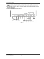
1
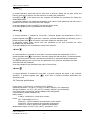
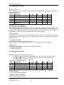
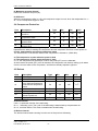
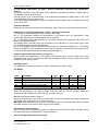
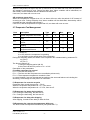
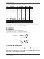
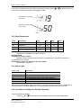
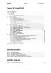
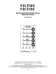
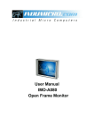
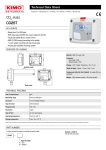
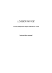
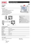
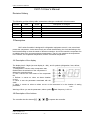
C207-14 User’s Manual
C207-14 User’s Manual
Revision History
The following revision history table summarizes changes contained in this document.
Revision
Revision
Author
Description of Changes
Number
Data
V1.00
02/09/2015 Tech07
Initial public release
1 Description
C207 series Controller is designed for refrigeration equipment control. It can control and
protect the compressor. At the same time it can control the defrosting, the circle defrosting or the
real time defrosting to meet the needs of different occasions. And it can control the evaporator fan.
In addition there are 3 types temperature measurement. That is it can measure the temperature
in the cabinet, the evaporator temperature, and the condenser temperature.
1.1 Description of the display
The display has 2.5 digits (Its most display is –188.), and 5 symbols (refrigeration, fans, defrost,
alarm and clock).
1. Refrigeration: It shows when compressor start,
flashes when the activation of the compressor is
delayed by protection times.
2. Fans: It shows the work status of the evaporator
fan.
3. Defrost: It comes on when an alarm situation
occurs.
4. Clock: It sets the parameter associated with the
clock.
5. Alarm: It comes on when an alarm occurs or the instrument is in the situation of setting
parameter.
FIG 1
Warnings: When you set the parameters, alarm symbol
flash frequency is 0.5 Hz.
1.2 Description of the buttons
The controller has four buttons
Howe Precision Industrial., INC
C207-14 Rev 1.0
Last Modify 2015-2-9
,
,
,
-1-
to operate the controller.
C207-14 User’s Manual
1 Button
In normal operation, press and hold for more than 3 seconds, display the set point; press and
hold for more than 5 seconds, access the menu for setting the parameters.
and
at the same time, the controller will activate the procedure for setting the
Press
default parameters.
In parameter setting mode: alternates the display of the value of each parameter with the name; if
pressed for more than 3 seconds saves the changes.
In set point display model, if press , the changes will be saved.
In set point display mode: if pressed saves the changes.
2 Button
In normal operation: if pressed for more than 3 seconds display the temperature of RT2; if
pressed together with
for more than 3 seconds, activates /deactivates the defrosting cycle; if
for more than 3 seconds, display the real time clock.
pressed together with
In parameter setting mode: moves from one parameter to the next; increases the value
associated with the parameter.
In set point display mode: increases the value of the set point.
3 Button
In normal operation: if pressed for more than 3 seconds, display the temperature of RT3; if
for more than 3 seconds, display the real time clock, if pressed together
pressed together with
with
for more than 5 seconds, activates the procedure for setting the default parameters.
In parameter setting mode: moves from one parameter to the previous; decreases the value
associated with the parameter.
In set point display mode: decreases the value of the set point.
4 Button
In normal operation: if pressed for more than 3 seconds changes the status of the controller
(ON/OFF), if pressed together with
defrosting cycle.
for more than 3 seconds activates /deactivates the
1.3 Technical specifications
Power supply: 115VAC±10%, or 230VAC±10%, 50/60Hz;
Operating conditions: -20~60oC (-4~140oF), humidity <90%RH, non-condensing;
Storage conditions: -30~70oC (-22~158 oF), humidity <90%RH, non-condensing;
Front panel index of protection: panel installation with IP65 gasket;
Communication: RS485, Modbus RTU;
Relay outputs:
3 relays, 10A/250VAC, normal open contact;
Probe:
NTC, 10Kohm@25 oC(77 oF).
Probe RT1: used to measure the temperature in the cabinet
Probe RT2: used to measure the evaporator temperature;
Probe RT3: used to measure the condenser temperature.
Measurement range: -45~99 oC (-49~199 oF), resolution 1 °C/°F;
Howe Precision Industrial., INC
C207-14 Rev 1.0
Last Modify 2015-2-9
-2-
C207-14 User’s Manual
Temperature accuracy: +/-1 oC (-20~30 oC), or +/-2 oF (-4~86 oF);
Communication: RS-485 bus, Modbus RTU mode.
2 Function and Parameter
Parameters can be divided into essential parameter and advanced parameters.
Essential parameter St is user set point.
Advanced parameters are divided into 8 types: P/ (probe parameter), Pr (temperature control
parameter), PC (compressor parameter), Pd (defrost parameter), PA (alarm parameter), PF (fan
parameter), Pt (clock defrost parameter) and PH (system parameter).
2.1 Modifying the Parameters
2.1.1 Accessing the essential parameter(St)
Setting method:
1 In normal operation, press
for 3 seconds, and then the display shows the current set point;
2 Press
or
to increase or decrease the value until to the desired value;
3 Press
to confirm the new value in order to save the new value and return to the normal
operation.
2.1.2 Accessing the Advanced Parameters
1 Press
2 Press
for more than 5S, and then the display shows the code of parameter “PS” (password);
to enter into the password set;
3 Press
4 Press
and
to scroll the number to “-15”;
to confirm the password and then the display shows “P/”;
and
to scroll the parameter type (P/, Pr, PC, Pd, PA, PF, Pt, PH);
5 Press
6 Press
to confirm the parameter type, and then the first parameter name of this kind of
parameter will be shown;
6.1 Press
6.2 Press
or
to scroll the parameters;
to display the relevant parameters;
or
to increase or decrease the value;
6.3 Press
6.4 Press
to save the modified value temporarily and return to the display of the
parameter;
6.5 Repeat the procedure 6.1-6.4 to modify the other parameters;
for more than 3 seconds to save modified parameter and return to the
6.6 Press
display of parameter type;
7 Repeat the procedure of 5-6 to modify the parameters of the other types;
for more than 3 seconds or no button is pressed within 60 seconds, exit the
8 If press
procedure of the parameter setting.
Warnings:
1 If no button is pressed for within 60 seconds, all the changes of parameters (the values saved
temporarily in the RAM) will be invalid. And the previous setting will be restored.
2 If the instrument is cut off before the parameters are saved, all the values saved temporarily in
the RAM will be lost.
Howe Precision Industrial., INC
C207-14 Rev 1.0
Last Modify 2015-2-9
-3-
C207-14 User’s Manual
2.2 Temperature Probes
Modify the probe:
Use the parameters in the following table to modify and stabilize the measured temperature by
the temperature probes.
Probe parameters:
Para
Description
Type
Min.
Max.
Unit
/0
Probe measurement stability
P/
1
15
o
Probe 1 offset
/1
P/
-5
5
C/ oF
o
C/ oF
Probe 2 offset
/2
P/
-5
-o
C/ oF
Probe 3 offset
/3
P/
-5
-/5
Select °C/°F
P/
o
C
o
F
--
Description of the Parameters:
/0 Probe Measurement Stability
This parameter defines the coefficient used to stabilize the temperature measurement. Low
values accelerate the response time of the probes; and the reading is however more sensitive to
the disturbance. High values slow down the response time of the probes but it’s not sensitive to
the disturbance. That is, it has a more stable and more precise reading.
/1 Probe 1 offset
This parameter is used to correct the measured temperature of probe 1. The symbol of the value
indicates that the temperature of probe 1 is added to (positive value) or subtracted from (negative
value) the offset.
/2, /3 Probe 2, 3 offset
The using way of /2 and /3 is the same as that of /1.
After the parameter value is set to the sign of “—”, this relevant probe will be disabled.
/5 Select °C/°F
Defines the unit of measure used for the control and the display.
°C = degrees centigrade
°F = degrees Fahrenheit
2.3 Temperature Control
Display or set the current temperature set point:
Press
for 3 seconds and then the display shows the value of the current set point;
Press
or
to increase or decrease the value until to reach the desired value;
Press
again to confirm the new value.
Temperature Control Parameters:
Para
Description
Type
Min.
Max.
Unit
o
St
User set point
r1
r2
C/ oF
r1
Minimum set point allowed
Pr
-40
r2
o
r2
Maximum set point allowed
Pr
r1
194
o
Pr
1
18
o
rd
Difference
Description of the Parameter:
St User set point
Users set the working temperature.
r1 Minimum set point allowed
Define the minimum set point (St).
Howe Precision Industrial., INC
C207-14 Rev 1.0
Last Modify 2015-2-9
-4-
C/ oF
C/ oF
C/ oF
C207-14 User’s Manual
r2 Maximum set point allowed
Define the maximum set point (St).
rd difference
When the temperature value is <=St, the compressor stops to work; when the temperature is >=
St + rd, the compressor begins to work.
2.4 Compressor Protection
Para
Description
Type
Min.
Max.
Unit
Compressor & fan start delay after
c0
PC
0
100
Min
power-on
Min. time between successive
c1
PC
0
100
Min
compressor starts
The compressor on time when the
c4
PC
0
99
Min
probe is fault
The compressor off time when the
c5
PC
1
99
Min
probe is fault
c0 compressor & fan start delay after power-on
Represents the delay in starting the compressor and the evaporator fans from control power-on.
C1 min. time between successive compressor starts
The time between 2 consecutive starts of the compressor is at least c1 (UOM: Min).
c4 The compressor on time when the probe is fault
c5 The compressor off time when the probe is fault
c4 = 0, the compressor will be always on when the probe (RT1) error is detected;
At the moment the probe (RT1) error is detected, the compressor run the duty setting cycle starts
from the current status of the compressor, and the time already elapsed is ignored.
2.5 Defrost
Para
d0
d1
dt
dp
d6
d8
dd
Description
Defrost type
Defrost interval
End defrost temperature set
point / defrost temperature
threshold with temperature
control
Defrost duration
Display when defrosting
Alarm bypass time after
defrost of power-on
Dripping time
Type
Pd
Pd
Min.
0
1
Max.
2
199
Unit
Hour
o
C/ oF
Pd
-40
199
Pd
Pd
0
0
199
2
Min
-
Pd
0
199
Min
Pd
0
15
Min
d0 defrost model
If d0 = 0, shield the function of the defrosting.
d0 = 1, defrosting cycle. The cycle of the defrosting is determined by the parameter d1.
d0 = 2, real time defrost. The clock set determines the defrosting.
d1 Defrost interval
The defrost interval starts counting from the end of the previous defrosting.
Howe Precision Industrial., INC
C207-14 Rev 1.0
Last Modify 2015-2-9
-5-
C207-14 User’s Manual
dt end defrost temperature set point / defrost temperature threshold with temperature
control
During the procedure of the defrosting, if the evaporator temperature (probe 2) is higher than dt,
the defrosting will not be performed.
Coming into the cycle of the defrosting, if the evaporator temperature is higher than dt, the cycle
of the defrosting will not be performed.
If the defrost probe is shielded or broken, the defrost will be stopped after a maximum time equal
to the value of dp.
dp defrost duration
Determine the maximum duration of the defrosting. After the period of dp, the defrosting will stop.
d6 display of controlling temperature “frozen” during the defrosting
This function is what the display shows during the defrosting.
d6= 0: The instrument displays the temperature in the cabinet and “dF” alternatively. After
finishing the defrosting, the normal display will be restored.
d6= 1: If the display during the defrosting is not locked, the instrument displays the last value read
before the current defrosting.
The display returns normally when the temperature in the cabinet is =< the set point (St) or after
the set alarm bypass time after the defrosting.
d6= 2: If the display during the defrosting is not locked, the instrument displays “dF”. The display
returns normally when the temperature in the cabinet is equal to or lower than the set point (st) or
for the set alarm bypass time after the defrosting (parameter 8).
d8 Alarm bypass time after defrost of power-on
When defrost, the temperature in the cabinet will become higher and the alarm of the high
temperature will not occur. Indicate the time after finishing defrosting. After the period of d8, that
an alarm occurs can be judged.
dd Dripping time
The parameter forces the compressor off after the defrosting in order to drip.
2.6 Alarm
Para
AL
Description
Low temperature alarm of probe 1
Type
PA
AH
High temperature alarm of probe 1
PA
Min.
-45
Max.
199
-45
199
unit
o
C/ oF
o
C/ oF
o
Ac
Condenser alarm set point
PA
-45
199
C/ oF
Ad
Probe 1 temperature alarm delay
PA
0
99
Min
AE
Condenser alarm delay
PA
0
99
Min
AL Low temperature alarm of probe 1
When the temperature in the cabinet (probe 1) is lower than AL and the condition meets the
temperature alarm delay (see parameter Ad), an alarm will occur.
AH High temperature alarm of probe 1
When the temperature in the cabinet is higher than AH and the condition meets the temperature
alarm delay (see parameter Ad), an alarm will occur.
Warnings: After the instrument is power on, the temperature in the cabinet alarm will be shielded.
And after a period of d8, that an alarm occurs will be judged.
Ac condenser alarm set point
When the condenser temperature (probe 3) is higher than the set point and the condition meets
the alarm delay (see parameter Ad), an alarm will occur.
Ad Low & High temperature alarm delay
Howe Precision Industrial., INC
C207-14 Rev 1.0
Last Modify 2015-2-9
-6-
C207-14 User’s Manual
When the temperature is higher than AH (or lower than AL), an alarm will occur after the period of
AE instead of occurring at once. During the delay time, alarm condition will be eliminated, an
alarm delay will be cancelled and the calculator will become 0.
If set Ad=0, an alarm will occur at once.
AE condenser alarm delay
When the temperature is higher than AC, an alarm will occur after the period of AE instead of
occurring at once. During the delay time, alarm condition will be eliminated, alarm delay will be
cancelled and the calculator will become 0.
If set AE=0, and the temperature is higher than AC, an alarm will occur at once.
2.7 Evaporator Fan Management
Para
F0
Description
Type
Min.
Max.
Unit
Enable evaporator fan control
PF
0
2
Evaporator fan controls set
o
F1
C/ oF
PF
-40
199
point
Evaporator fan status during
F3
PF
0
1
defrost
Evaporator fan delay after
F4
PF
0
99
Min
dripping
Evaporator fan controls the
o
Fd
C/ oF
PF
1
18
temperature difference
In normal operation, the evaporator fans can be managed in the following models:
1 always on
2 on only when the compressor is operating
3 on according to the temperature of the evaporator
During the defrosting model, the status of the evaporator fan is determined by parameter F3:
on (F3=0)
off (F3=1)
The fans are always off:
1 during the dripping period (dd ≠0)
2 when the instrument is power on c0(c0 ≠0)
Description of the parameters:
F0 enable evaporator fan control
F0 = 0: The fans are always on.
F0 = 1: The fans and the compressor are controlled synchronously.
F0 = 2: The evaporator temperature controls the fans.
In normal situation, fans can be operated according to the set model above not including the
defrosting, the drainage and the power-on instrument.
F1 Evaporator fan controls set point
Evaporator fans control the set point.(F0=2)
When the evaporator temperature is <=F1, fans are on.
When the evaporator temperature is >=F1+Fd, fans are off.
F3 Evaporator fan status during defrost
F3=0: During the defrosting, the fans are on.
F3=1: During the defrosting, the fans are off.
F4 Evaporator fan delay after dripping
After dripping, it needs 4-time delay to start the fans.
Fd Evaporator fan controls the temperature difference
The fans control the temperature difference (see parameter F1).
Howe Precision Industrial., INC
C207-14 Rev 1.0
Last Modify 2015-2-9
-7-
C207-14 User’s Manual
2.8 Real Time Defrost and On & OFF controller
Para
t1
t2
t3
t4
t5
t6
O1
F1
O2
F2
O3
F3
O4
F4
Description
Defrosting time 1
Defrosting time 2
Defrosting time 3
Defrosting time 4
Defrosting time 5
Defrosting time 6
ON status time 1
OFF status time 1
ON status time 2
OFF status time 2
ON status time 3
OFF status time 3
ON status time 4
OFF status time 4
Type
Pt
Pt
Pt
Pt
Pt
Pt
Pt
Pt
Pt
Pt
Pt
Pt
Pt
Pt
Min.
00:00
00:00
00:00
00:00
00:00
00:00
00:00
00:00
00:00
00:00
00:00
00:00
00:00
00:00
Max.
24:00
24:00
24:00
24:00
24:00
24:00
24:00
24:00
24:00
24:00
24:00
24:00
24:00
24:00
Unit
HH:MM
HH:MM
HH:MM
HH:MM
HH:MM
HH:MM
HH:MM
HH:MM
HH:MM
HH:MM
HH:MM
HH:MM
HH:MM
HH:MM
t1~t6 defrosting time
When set t1~t6, you can switch the setting from “hour” to “minute”, such as FIG 2.
If the clock runs to the setting hour and the parameter d1=0, the instrument begins to defrost.
If the value is 24:00, display “- -”, means this time is disabled.
O1, F1 ON/OFF time 1
O2, F2 ON/OFF time 2
O3, F3 ON/OFF time 3
O4, F4 ON/OFF time 4
Ox ON status start time, Fx OFF status start time.
If the value is 24:00, display “- -”, means this time is disabled.
Note: if the value of Fx less than Ox, means the Fx time as next day.
Setup Hour
Setup Minute
FIG 2
2.9 Clock and Time Band Parameters
When the controller is in the normal model, press
together with
for 3 seconds in order to
is light and the
enter into the clock view / setting model (see FIG 3), and then the indicator
to switch to the minute
display shows the current time (hour, 24-hour system). And press
display. Then you can press
to exit the time display.
Howe Precision Industrial., INC
C207-14 Rev 1.0
Last Modify 2015-2-9
-8-
C207-14 User’s Manual
If the time is needed to set and when it is checked, please press
become the correct time and then press
to confirm.
or
to adjust the time to
Indicate the current UOM
to be “hour”
Indicate the current UOM
to be “minute”
FIG 3
2.10 Other Parameters
Para
H0
H2
H3
Description
Type
Min.
Max.
Unit
Modbus address
PH
1
99
Not defined
PH
00
01
Software version number
PH
Parameter values are
H4
PH
derived to the quick editor
H0 Modbus address
The address of Modbus is for communication.
H2 Not defined
H3 Software version number
Software version number can be viewed by this parameter. It cannot be set and it is
onboard data of the system.
H4 Parameter values are derived to the quick editor
This function is reserved.
2.11 Alarm Code
Alarm code
E0
E1
E2
Lo
Hi
CH
Description
Probe 1 fault (control)
Probe 2 fault (evaporator)
Probe 3 fault (condenser)
Low temperature alarm in the cabinet (probe 1)
High temperature alarm in the cabinet (probe 1)
Condenser (probe 3) temperature alarm
When the controller displays alarm code above, check the relevant equipment or accessories, or
check whether the controller parameter set is appropriate according to the relevant code.
2.12 Procedure for Setting the Default Parameter
To set the default parameter:
1 Press
and
at the same time, the display shows the current default class;
Howe Precision Industrial., INC
C207-14 Rev 1.0
Last Modify 2015-2-9
-9-
C207-14 User’s Manual
2 Continue hold the buttons for more than 5 seconds, the value is flashed, then releases
the buttons;
or
to change the value(00, 01, 0F, 1F)until to the desired value;
3 Press
4 Press
for more than 3 seconds confirm the new value, and exit to normal operation.
All the default value of parameter will be loaded automatically.
2.13 Parameter List
Para
Description
/1
Probe measurement
stability
Probe 1 offset
/2
Probe 2 offset
/3
Probe 3 offset
/0
/5
St
r1
r2
rd
c0
c1
c4
c5
d0
d1
dt
dp
d6
d8
dd
AL
AH
Select °C/°F
User set point
Minimum set point
allowed
Maximum set point
allowed
Difference
Compressor & fan
start delay after
power-on
Min. time between
successive
compressor starts
The compressor on
time when the probe
is fault
The compressor off
time when the probe
is fault
Defrost type
Defrost interval
End defrost
temperature set
point / defrost
temperature
threshold with
temperature control
Defrost duration
Display when
defrosting
Alarm bypass time
after defrost of
power-on
Dripping time
Low temperature
alarm of probe 1
High temperature
alarm of probe 1
Howe Precision Industrial., INC
C207-14 Rev 1.0
Last Modify 2015-2-9
Type
P/
P/
P/
Min.
Max.
1
15
-5
-5
00
1F
4
4
4
4
5
o
0
0
0
0
--
o
o
0
0
0
0
o
o
-5
--
P/
o
o
-
Default class
01
0F
o
P/
C
Unit
C/ F
C/ F
C/ F
--
F
0
0
-24
-3
-11
27
C
o
0
o
C
F
o
F
-
r1
r2
o
Pr
-40
r2
o
-30
-10
-22
14
Pr
r1
194
o
-15
10
5
50
Pr
1
18
o
C/ oF
3
3
5
5
PC
0
100
Min
0
0
0
0
PC
0
100
Min
3
3
3
3
PC
0
99
Min
30
30
30
30
PC
1
99
Min
20
20
20
20
Pd
Pd
0
1
2
199
Hour
2
8
2
8
2
8
2
8
Pd
-40
199
o
C/ oF
8
8
46
46
Pd
0
199
Min
30
30
30
30
Pd
0
2
-
2
2
2
2
Pd
0
199
Min
30
30
30
30
Pd
0
15
Min
5
5
5
5
PA
-45
199
o
C/ oF
-35
-8
-31
18
PA
-45
199
o
-7
5
19
41
- 10 -
o
0
o
C/ F
C/ oF
C/ oF
C/ oF
C207-14 User’s Manual
Ac
Ad
AE
F0
F1
F3
F4
Fd
t1
t2
t3
t4
t5
t6
O1
F1
O2
F2
O3
F3
O4
F4
H0
H2
H3
H4
Condenser alarm
set point
Probe 1 temperature
alarm delay
Condenser alarm
delay
Enable evaporator
fan control
Evaporator fan
controls set point
Evaporator fan
status during defrost
Evaporator fan delay
after dripping
Evaporator fan
controls the
temperature
difference
Defrosting time 1
Defrosting time 2
Defrosting time 3
Defrosting time 4
Defrosting time 5
Defrosting time 6
ON status time 1
OFF status time 1
ON status time 2
OFF status time 2
ON status time 3
OFF status time 3
ON status time 4
OFF status time 4
Modbus address
Not defined
Software version
number
Parameter values
are derived to the
quick editor
C/ oF
55
55
131
131
99
Min
10
10
10
10
0
99
Min
10
10
10
10
PF
0
2
-
0
0
0
0
PF
-40
199
C/ oF
5
5
41
41
PF
0
1
-
0
0
0
0
PF
0
99
Min
0
0
0
0
PF
1
18
C/ oF
2
2
3
3
Pt
Pt
Pt
Pt
Pt
Pt
Pt
Pt
Pt
Pt
Pt
Pt
Pt
Pt
PH
00:00
00:00
00:00
00:00
00:00
00:00
00:00
00:00
00:00
00:00
00:00
00:00
00:00
00:00
1
24:00
24:00
24:00
24:00
24:00
24:00
24:00
24:00
24:00
24:00
24:00
24:00
24:00
24:00
HH:MM
HH:MM
HH:MM
HH:MM
HH:MM
HH:MM
HH:MM
HH:MM
HH:MM
HH:MM
HH:MM
HH:MM
HH:MM
HH:MM
08:00
16:00
00:00
--:---:---:---:---:---:---:---:---:---:---:--
99
-
08:00 08:00
16:00 16:00
00:00 00:00
--:---:---:---:---:---:---:---:---:---:---:---:---:---:---:---:---:---:---:---:---:---:-Not changed
PH
00
01
-
Not changed
PH
-
-
-
-
-
-
-
PH
-
-
-
-
-
-
-
PA
-45
199
PA
0
PA
o
o
o
2.14 Communication
The controller used RS-485 bus interface, Modbus RTU type.
Communication set up: baud rate 9600bps, 1 stop bit, no parity, non-zero.
Registers define reference document <C207-14 Modbus registers definition >.
3 Wiring Diagram
Wiring diagram is FIG 4.
Warnings:
Howe Precision Industrial., INC
C207-14 Rev 1.0
Last Modify 2015-2-9
- 11 -
08:00
16:00
00:00
--:---:---:---:---:---:---:---:---:---:---:--
C207-14 User’s Manual
1 Before use, please first confirm whether the power supply and the voltage can meet power
supply’s need of controllers. Or the instrument can’t run normally, and even it is burned to
destroy.
2 If the instrument doesn’t be used for a long time, please confirm whether its clock is accurate
before it is used again.
3 Connection terminal screw torque: 5Kg-cm.
FIG 4
Howe Precision Industrial., INC
C207-14 Rev 1.0
Last Modify 2015-2-9
- 12 -