1
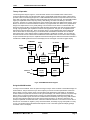
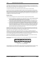
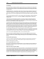
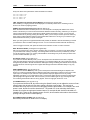
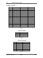
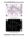
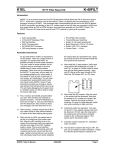
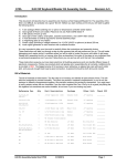
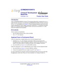
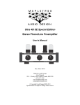
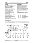
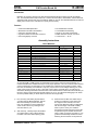
K1EL
K-40CW
CW Decoder Board Kit
Introduction
K40CW is an accessory board for the K40 CW Keyboard that allows the K40 to decode and display
CW. The K40CW board accepts audio from a receiver and then filters, demodulates, and decodes CW
characters which are then fed over to the K40 for display on its LCD. The K40CW board has an LED bar
display that is used to tune CW stations in quickly and accurately.
Features
•
•
•
•
•
•
•
•
•
•
4 Pole Active Bandpass Filter
Quadrature Correlation demodulator
Fixed tone decode at 690 Hz
Cypress CY8C27143-24 PSoC Processor
LED tuning display on board
PIC12F508 LED controller
Transmit/Receive Switching
Single +5 volt supply requirement
Board dimension: 2.25 by 3.0 inches
Current Draw: < 10 ma
Assembly Instructions
Bill of Materials
Reference
K40CW PCB
U1
U2
U3
D1-D6
R11,R12
R10
R4,R5,R7
R3,R8
R9
R6,R2
R1
C2, C7
C1,C5,C6,C10
C11
C3,C4,C8,C9
Position U1
Description
K40CW Printed Circuit Card
CY8C27143 PSoC Controller
LMC6482 Dual Op Amp
PIC12F508 Display Controller
LED Display
270 Ω 5% Resistor
4.7K Ω 5% Resistor
10K 5% Resistor
33.2K 1% Resistor
4.64K 1% Resistor
66.5K 1% Resistor
9.76K 1% Resistor
33 µf capacitor
.01 µf 100 VDC capacitor
.1 µf ceramic capacitor
.012 µF mylar capacitor
8 Pin DIP Socket
Package
PC Board
8 pin PDIP
8 Pin PDIP
8 Pin PDIP
2 Pin
1/4 W
1/4 W
1/4 W Blue
1/4 W Blue
1/4 W Blue
1/4 W Blue
1/4 W Blue
electrolytic
ceramic disc
.1” lead space
Dipped radial
8PDIP
Check
An accurate DVM or VOM is highly recommended for this project. There are several precision 1%
resistors that MUST be installed correctly to insure proper operation. The color codes on these resistors
can be confusing and an ohmmeter is a very reliable way to determine which resistor is which. Other
than that, the assembly of the K40CW is very easy; all you need is a low wattage soldering iron, some
solder, a few pieces of hook up wire, a good pair of wire cutters, and small pliers. You will need an
assembled, working K40 board to test and check out the K40CW board. These instructions will take you
through a step by step process that will test portions as you go. This will make debugging much easier
since if a problem arises you will be able to locate the source right away.
1)
First, inventory and identify all parts before
you start using the Bill of Materials. This will
allow the assembly to proceed smoothly.
Use your ohmmeter to sort the resistors by
value. Email us about any shortages and
we’ll send them to you.
2)
After inventory, carefully inspect the PCB for
any solder shorts or other obvious defects,
it's easier to find them before placing parts.
K40CW User’s Manual – Rev 1.0
3)
2/5/2008
Start with the six LEDs, the easiest way to
do this is to install one of the center ones
first. Align the LED carefully to be in the
center of the silkscreen with front edge flush
with the front edge of the PCB. Carefully
solder in place. One by one install the
remaining five LEDs insuring that each LED
is spaced evenly and is flush with the front
edge. I solder one lead on each first so I can
go back and individually tweak them before
soldering the second lead. It’s important to
Page 1
K1EL
K40CW CW Decoder Board Manual
pins 1 and 7 (TP2). These are analog input
and output and should be biased at analog
reference. Again, if you don’t see 2.5 volts
check the connections on U1 particularly the
power pins and bypass caps. Remove power
after testing.
do a good job so that the LEDs fit correctly
through the front panel of the enclosure.
4)
Next install the ¼ watt resistors. Verify each
value with the Bill of Materials on Page 9 and
Fig 7 on page 11. Double check to make
sure you place them correctly. I start with R1
and go all the way through to R12.
1
8
5)
Install the DIP socket at U1. Align the notch
in the socket with the silkscreen. It’s easy to
accidentally bridge adjacent pins when
soldering so take your time.
6)
Install and solder the capacitors. Two caps,
C2 and C7 have polarity markers that must
be observed. On both caps the long lead is
the positive lead and should be installed
closest to the + silkscreen legend. (The
square pad is the positive side)
7)
Now wire the K40CW board to the K40
board as shown in Fig. ? on Page ??. (If you
purchased the K40 enclosure, follow the
detailed wiring harness instructions) Note
that there are three signal connections, +5V
and two grounds. After this step, but before
installing any ICs, turn the K40 power on and
verify the following voltages:
U1:
U2:
U2:
U2:
U3:
8)
9)
11) Now it’s time to check out the K40CW tone
filters. Connect an audio frequency
generator or receiver audio output to the AF
input on the K4CW board. The level should
be around .5V peak to peak, preferably a
high impedance output (600Ω). You can use
speaker audio out but you may need a
higher level. If you are using a receiver, turn
on calibrate or tune in a carrier signal to get
a beat note. If you are using a signal
generator set it to 690 Hz. Power up the K40
and make sure that it is in CWR ON mode
(Press ALT-F1) Tune up and down slowly
until you see some activity on the LED
display. You may have to play with the audio
level. As you tune you will first see LEDs
light on the left side and then peak to the
right as you tune through 690 Hz. The
maximum swing should be at 690 Hz. If your
audio level is too low you may not see a full
swing tune. Try increasing the gain by
holding down the shift key and turning the
speed control. If you are having problems
read through the theory of operations and
check the signal path through the filter. TP1
and TP2 are useful for this (see page 7)
Pin
Pin
Pin
Pin
Pin
8
8
3
5
1
+5V
+5V
+2.5V
+2.5V
+5V
Pin4
Pin4
Pin4
Pin4
Pin8
12) Now let’s try to tune in some CW stations.
Connect AFIN to your receiver’s audio
output. Make sure you are still in CW
receive mode (ALT-F1). When no station is
tuned in, the LEDs should be out or flicker
dimly. You may see an occasional random
character if there is lot of noise on the band.
As you approach proper tuning you will see a
deflection across the display in sync with the
keyed CW. As soon as you are tuned in,
letters will appear on the K40 display. The
K40CW does a pretty good job of following
bad sending but it can’t copy letters that are
run together or badly timed dits and dahs.
Ground
Ground
Ground
Ground
Ground
If you don’t see these voltages, carefully
check your solder connections and look for
any shorts or opens. The 2.5V bias is the
analog referece for the active bandpass
filter. It is determined by the voltage divider
R4 and R5.
13) You can improve noise immunity to some
degree with the adjustable noise filter. This is
adjusted by holding down the ALT key and
turning the speed control. There are eight
levels with 0 meaning less filtering up to 8 for
increased filtering. Higher filtering will
compromise faster WPM copy.
Install and solder in U2 and U3. Power on
again and re-measure the voltages to make
sure they are still correct. Turn power off and
on again and watch the LED display, you
should see a power up LED test in which
each LED is turned on and off in sequence.
Make sure all LEDs light one at a time.
When the test is over all LEDS will turn off.
17) That's it! After reading through the theory of
operations it’s on to the command section to
learn about the K40CW command set.
10) Turn power off again and install U1, power
up again and you should see 2.5 volts on
K-40CW User’s Manual Rev 1.0
2/5/2008
Page 2
K1EL
CW Decoder Board Kit
K-40CW
Fig 1 - Assembled K40 CW PC Board
K40CW User’s Manual – Rev 1.0
2/5/2008
Page 3
K1EL
K40CW CW Decoder Board Manual
Wiring the K40 CW Module into the K40 Enclosure.
The K40 enclosure has a slot to place the K40 CW module, Before attaching the board to the
enclosure there are some wires that must be attached. There are five wires between the K40 PCB
and the K40 CWR PCB as shown below. In addition there are two wires from the K40CW board to the
AF IN RCA jack on the K40 enclosure. This is the jack the receiver audio is connected to.
Fig 2 - K40 Connections to K40CWR
Audio Input
from Receiver
AF_IN
G
This is wired to the
AF IN RCA jack on
the K40 Enclosure
Audio Input impedance
is approx 1K ohms
5 volts PtP maximum
TR
U2.7
TI
U2.8
RO
KEY
G
RY
KEY and PTT are both open
collector transistor outputs.
50 VDC, 100ma max to ground.
K40
K40 CW
PCB
CW KEY is pulled low:
on Key down
PTT
G
G
PTT is pulled low
on transmit.
G
Fig 3 - K40 to K40 FILT Interconnect
K-40CW User’s Manual Rev 1.0
2/5/2008
Page 4
K1EL
K40CW CW Decoder Board Manual
Theory of Operation
The following block diagram, Figure 4, shows the basic sections of the K40CW board. Audio from the
receiver is filtered through an initial active filter stage. The bandwidth of this stage is approx. 400 Hz which
provides coarse out of band signal rejection. A wider bandwidth also allows for component tolerances in the
active filter. This stage also isolates and protects the PSoC processor from the input. The LMC6482 handles
large input amplitudes well and clips very cleanly. After filtering, the audio is fed directly to the PSoC
processor. The PSoC is a mixed signal device which contains both analog and digital function blocks. These
blocks, as well as the connections between the blocks, are programmable. This allows a very sophisticated
design to be implemented in a very small package. The clock that runs the PSoC is contained within the
device and is set at 24 MHz. The signal chain inside the PSoC is described next. First the signal is passed
through a programmable gain amplifier to boost low level signal levels. This gain can be adjusted via the
K40 speed control and SHIFT key. Next, the signal is fed to a 4 pole bandpass filter that is implemented
with an SCAF filter he center frequency is set to 690 Hz with a bandwidth of about 200 Hz. The filtered
signal is then fed to a tone detector which is implemented with a quadrature correlator. The recovered dit
and dah intervals are then measured and translated into ASCII letters which are sent to the K40 for display.
As part of the detection process, the amplitude of the filtered CW signal is determined and this information is
formatted as a PWM signal which is fed to the display PIC U3 which lights a six LED bar graph display.
LMC6482
Audio
Input
(AF)
690Hz
PIC12C508
Input
4 pole
Bandpass
LED
Driver
Tuning
LEDs
PWM
Amplitude
PGA
PSoC
To/From
K40
TI
RO
SCAF BPF
4 pole
690Hz
Tone
Decoder
PSoC
PSoC
Serial
Comm
ASCII
Translation
PSoC
PSoC
Decoded
Dits/Dahs
Fig 4 – K40CW Board Block Diagram
Using the K40CW module
It’s easy to use the K40CW. There are just a few things to keep in mind. The filters in the K40CW design are
fixed at 690 Hz. This just means that you need to adjust your receiver so that its passband is centered on
690 Hz. When you hear a station, slowly tune the station while watching the LED display on the K40CW
module. Watch for a peak LED movement to the right of the display. You will see a peak as you pass though
690 Hz. Once you have the station tuned in properly, CW will be decoded and displayed. Although the
filtering on the K40CW is good, there are two conditions that it has difficulty with. Very strong static crashes
and very strong adjacent stations. So if either of these things is present, you will see a decrease in the
quality of copied CW. As mentioned before, a bad fist is a bad fist and there’s not much that can be done to
decode one. Characters run together, poorly constructed letters, and widely varying code speed is not easy
to copy. You will also find that the K40CW will respond to noise or off tuned signals and display garbage
characters on the LCD display.
K-40CW User’s Manual Rev 1.0
2/5/2008
Page 5
K1EL
K40CW CW Decoder Board Manual
The K40CW will automatically track the CW speed as it changes and will lock on to a new station’s speed
within a letter or two. Sometimes noise in the background can cause the K40CW to lose speed lock and can
fool the speed locking logic. Again, noise makes it tough to copy.
The upper Rx speed about 40 to 45 WPM with upper limit influenced by the noise filter setting.
You can show the current receive WPM by hitting ALT-TAB. This will momnetarily show the approximate
speed of the CW currently being copied by the K40 CWR. Note that the speed is determined by the average
width of received dits. This means that it can be fooled by Farnsworth formatted CW. For example if you
copy W1AW code practice at 10 WPM, the K40CWR will report 18 WPM since the code practice is sent at
10 WPM with a Farnsworth speed of 18 WPM.
K40CW Settings
There are several settings that can be issued from the K40 to configure the K40CW operation.
1)
2)
3)
Gain can be adjusted to compensate for low or high receiver volume. There are eight gain settings.
Gain is adjusted by holding the Shift key down while turning the speed control. As you turn the
knob the current setting is displayed momentarily on the LCD display.
The low pass noise filter is also adjustable. There are eight settings from minimal filtering (01) to
maximum filtering (08). Filtering is adjusted by holding the ALT key down and turning the speed
control. As you turn the knob the current setting is displayed momentarily on the LCD display.
Inter-element spacing allowance can be adjusted too. This helps compensate for incorrect spacing
between dits and dahs which can cause letters to be run together or broken apart. This has four
ranges and is adjusted by holding the CTL key down while turning the speed pot. Smaller values
expect less space between elements (fixes case where an R prints as ETE) while large values
expect more space (fixes case where ETE prints as R).
ASR Mode automatically toggles the display window from receive to transmit when the user types on the
keyboard. When ASR is enabled you must pause the output (INSERT key) before typing into the transmit
buffer. When insert is pressed again the transmit buffer is released and sent.
TXMON mode allows both paddled and keyboarded Morse to be shown in the Receive window as a
convenience. Received letters are displayed in upper case while transmitted letters are displayed in lower
case. Normally only received characters are displayed in the receive window. No matter what mode you are
in you can always toggle between the transmit and receive windows with the TAB key.
The accuracy of CW decoding can vary as a signal fades in and out. With very deep fades, the K40 may
print an erroneous character or get out of sync for a couple of characters.
You can turn the K40CW module off using the ALT-F1 command. With the module turned off it will draw
minimal power.
Low Signal Level
High Signal Level
Fig. 5 – CW Level Indicator LEDs
The LED display is a very simple indication of both tuning accuracy and signal strength. Note that a change
in signal strength will cause movement in the display similar to a signal being tuned in by frequency.
K-40CW User’s Manual Rev 1.0
2/5/2008
Page 6
K1EL
K40CW CW Decoder Board Manual
Transmitting
When the CW reader is enabled, the K40 KEY output is used to key your transceiver as it normally would.
You can either type on the keyboard or use a paddle set to enter letters to transmit. When in CWR mode,
the default display view is receive. To view the transmit buffer and see what you are typing hit the TAB key
to toggle the view.
As described previously, a handy feature is ASR mode, when this is turned on the display will toggle to the
transmit view as soon as you start typing. When you stop or pause the display will return to receive view.
Transmit view is identified by an underline cursor that indicates the text entry point. The cursor is turned off
in the receive view. The user can toggle between the receive and transmit views manually by using the TAB
key.
You can scroll back though the buffer ine at a time using the PGUP and PGDN keys. Hitting the HOME key
returns the buffer back to the active line. You can’t use END for scrolling, that key is used for fast
callsign entry!!
While receiving, the K40 supports type ahead so you can enter a response message while reading an
incoming message. You can quickly toggle to the Tx buffer with the TAB key to check a spelling or see
where you are. Hit TAB again to get back to the incoming display. The Caps Lock light on the keyboard will
flash when there are characters in queue waiting to be sent.
The transmit monitor command Shift-F4 is useful in some cases. It allows you to monitor real time transmit
progress in the receive window and will show messages fully expanded instead of message token letters.
When TX monitor is on, the transmit stream is printed in lower case in the Rx window. The LCD window is
not toggled back and forth with transmit/receive in this mode since everything can be seen in one window.
You still can toggle the display manually with the TAB key. TX monitor can produce quite a cluttered display
and I only use it to verify that messages are being sent the way I expect. It’s useful in contests when you
are using the fast callsign entry feature and want to be sure you entered callsigns correctly.
A nice K40 feature is fast callsign entry. Pressing the END key will open up a small window in the upper left
corner of the display where you can enter a callsign. When you hit return, the callsign will be copied into the
F12 message slot. This is great for contest exchanges. Try entering a message formatted like this:
^K^M ^C<F12> DE K1EL 5NN 5NN NH NH QSL ^C<F12> DE K1EL QSL? ^M^K
Now you can quickly enter different callsigns into the F12 slot using the END key and reuse the above
message over and over again. Note that the CALL token ^C is used to call the message in F12 and then
return. If you did insert a ^C, before the message it would jump to the F12 slot and stop when that message
finished.
Command Description by Key
There are no changes to the existing K40 commands, please refer to the K40 manual for information on
these. There are only a couple of new commands added to support the K40CW module and are only
available in chipset revision G or higher.
ALT-F1 Toggle K40CW module on and off
When this key is pressed it will turn the K40CW module on or off. A message is shown on the display that
states which one. When the K40CW module is off it will not respond to audio input and will not send any
decoded CW to the K40.
SHIFT-F3 Set ASR and TX Monitor Modes
This is a new command added for K40CW support. With ASR on, the K40 will toggle back and forth between
receive and transmit display buffers when characters are typed on the keyboard. This frees you from having
to hit the TAB key to flip the windows back and forth. Actual transmit is still controlled by the INSERT key. If
you want to type ahead and not transmit, pause the output with the INSERT key. When you are ready to
release the buffer, hit INSERT again. A blinking CAPS LOCK LED on the keyboard will indicate when output
is paused. You can hold the transmit display for a longer period of time by increasing the Tail time.
K-40CW User’s Manual Rev 1.0
2/5/2008
Page 7
K1EL
K40CW CW Decoder Board Manual
Every time SHIFT F3 is pressed the modes will advance as follows:
ASR
ASR
ASR
ASR
OFF TXMON OFF
OFF TXMON ON
ON TXMON OFF
ON TXMON ON
TAB: Toggle Receive/Transmit Display Window (Unchanged from Original K40)
Either incoming or outgoing streams can be displayed. The TAB key selects which. A blinking cursor is
shown in the transmit (outgoing) window.
INSERT: Receive/Transmit Control (Modified for K40 rev G)
When the K40CW module is enabled (see ALT-F1 command) the LCD display will default to the receive
window. This allows you to view received CW that the K40CW module is decoding. If desired, you can press
insert to pause transmit and type ahead, but the display window will remain in receive. You can view the
transmit window at any time by pressing the TAB key. When you are ready to transmit, press the insert key
again and PTT will be asserted and text in the transmit buffer will be sent. As long as you continue to type
the K40 will transmit unless you press Insert again.
When you have typed into the typeahead buffer while paused, the SCROLL LED will start blinking to remind
you that there is text in the buffer waiting to be sent. You can cancel the transmit buffer with the ESC key.
Insert is a toggle command, each press will advance from transmit->receive or receive->transmit.
ESC: Abort/Clear Buffer (unchanged from original K40)
ESC can be pressed at any time to abort a message, abort a command, or to clear the type ahead buffer. If
you press ESC while entering a message the message buffer will be cleared and you effectively can start
over at the beginning. (Note: You need to press ENTER to exit message entry mode, ESC just clears what
you have entered and starts you over)
ALT-Speed Control (new for K40 rev G)
If you press and hold the ALT key while you turn the Speed Control the K40CW noise filter is adjusted.
There are eight settings ranging from minimal filtering (1) to maximum filtering (8). This controls the cutoff of
the digital low pass filter in the CW demodulator. With higher settings of filtering, the K40CW will not respond
to shorter bursts of noise and ignore them. Higher filter settings reduces the K40CW’s ability to copy very
fast CW.
SHIFT-SPEED Control (new for K40 rev G)
If you press and hold the SHIFT key while you turn the Speed Control the K40CW gain is adjusted. This
allows you to tailor the K40CW module for differing input levels. Depending on what the source of the audio
input is (line out, headphone jack, 600 ohm output, speaker output) the signal level can vary widely.
Adjustable gain allows you to compensate for this. For best result, adjust the gain so that the loudest signal
just barely lights the right most LED. This insures that you have sufficient gain to copy weak signals while
not overdriving the K40CW module on strong signals. There are eight gain levels from 1 to 8.
CTL-SPEED Control (new for K40 rev G)
If you press and hold the CTL key while turning the Speed Control you can adjust the amount of interelement space the decoder will use when making a decision to end a letter. This can help in
situations where ops use too much or too little space between dits and dahs. For example if too much
space is used, dit dah dit could be decoded to E T E instead of R. It can also help where faster
senders do not allow enough space between letters. For example dit dah dah dit is decoded to P
instead of A N. There are four spacing ranges, 00 to 03, where smaller values reduce inter-element
spacing and larger values increase spacing.
ALT-TAB Show Receive WPM (new for K40 rev G)
Momentarily shows the Rx WPM in the LCD display.
K-40CW User’s Manual Rev 1.0
2/5/2008
Page 8
K1EL
K40CW CW Decoder Board Manual
K40CW Specifications
CW Receive
Fixed Rx Tone
Input Level
Speed Rate
Tuning Indication
Gain Settings
Noise Filtering
Inter-element Spacing
Speed Read Back
ASR Mode
690 Hz
1V nominal 5V max peak to peak.
10 to 45 WPM
Six LEDs frequency bar graph, auto squelch
Eight gain levels
Eight Digital low pass filter settings
Four spacing intervals, narrow to wide
Displayed upon key press
Automatic display buffer toggle
K40 CW PCB Testpoints
There are two test points that can be used to verify the operation of the K40 CW PCB.
TP1: Audio output of the 4 pole active filter before entering the PSoC Controller. By applying a signal
generator to the K40CW audio input and sweeping this from 600 to 800Hz a peak response will be observed
at this test point at approximately 690Hz +/- 20 Hz.
TP2: Audio Ouput of the PSoC’s internal 4 pole SCAF filter. In the same manner as above a peak response
can be seen at 690 Hz. This test point can also be configured to show the logic decode of received morse
tones such that no tone will produce a 0 volt level while tone present will produce 5 volts. The test point is
configured with a special diagnostic command.
K-40CW User’s Manual Rev 1.0
2/5/2008
Page 9
K1EL
K40CW CW Decoder Board Manual
Immediate Commands
Key
F1
F2
F3
F4
F5
F6
F7
F8
F9
F10
F11
F12
↑ UP
↓ DOWN
END
PGUP
PGDN
HOME
TAB
ESC
INSERT
Normal
Play Message 1
Play Message 2
Play Message 3
Play Message 4
Play Message 5
Play Message 6
Play Message 7
Play Message 8
Play Message 9
Play Message 10
Play Message 11
Play Message 12
N/A
N/A
Fast F12 Msg Load
Scroll Display Up
Scroll Display Down
Return display to home
Toggle Display view
Abort/Cancel
Tx/Rx Control
Shift
Record
Set ASR/TXMON
Toggle Spot
N/A
N/A
Toggle Tune
N/A
N/A
N/A
N/A
N/A
N/A
N/A
N/A
N/A
N/A
Clear LCD Displays
N/A
N/A
ALT
Toggle CWR Mode
Set Lead-in Delay
Set Tail Delay
Set Serial Number
N/A
N/A
N/A
N/A
N/A
Beacon Message
N/A
N/A
N/A
N/A
N/A
N/A
Show Rx WPM
N/A
N/A
Table 2
Speed Pot Control
Hold Key
None
SHIFT
ALT
CTL
Speed Pot Adjusts
Sending speed
K40CW Rx Gain
Noise Filter
Rx spacing allowance
Table 3
Buffered Commands
CTL
C
D
I
K
L
M
N
W
Z
Command
Call Message
Serial # -1
Serial #+1
Toggle Tx
Load Loop Count
Insert CR
Play Serial#
Wait
DECSZ Loop
Syntax
^C<msg>
^D
^I
^K
^L<nn> nn=count
^M
^N
^W<nn> nn=seconds
^Z
Table 4
K-40CW User’s Manual Rev 1.0
2/5/2008
Page 10
K1EL
K40CW CW Decoder Board Manual
Fig 6 - K40CW PCB Checkplot
Fig 7 - K40FILT PCB Top Solder Layer
K-40CW User’s Manual Rev 1.0
2/5/2008
Page 11
K1EL
K40CW CW Decoder Board Manual
Fig 8 - K40FILT PCB Bottom Solder Layer
Fig 9 - K40FILT PCB Reference Designators
K-40CW User’s Manual Rev 1.0
2/5/2008
Page 12
K1EL
K-40CW
CW Decoder Board Kit
3
4
5
6
7
A
2
A
1
B
PAD
6
5
33.2K
PAD
+
R3
7
U2A
2
3
33.2K
LMC6482
R9
4.64K
TP1
-
1
1
+
4
.012uf
R10
4.7K
1
-
.012uF
8
1
LOW_AF
R2
66.5K
C4
U2B
R8
.1uF
AGND
C3
.012uF
C9
C11
AF_IN
5V
R6
66.5K
B
C8
.012uF
PAD
LMC6482
R1
9.76K
GND
GND
C5
.01uF
GND
GND
C
GND
C
5V
R5
10K
GND
AGND
33uF
C7
C6
R4
10K
.01uF
5V
PAD
D
D
5V
1
C2
GND
33uF
GND
PAD
E
..
GND
1
K40CW User’s Manual – Rev 1.0
2
3
2/5/2008
4
5
Page 13
6
E
GND
Title
K40 CW Reader
Author
Steve Elliott
K1EL Systems
File
C:\bk\keyers\k40\K40cw\SCH\k40cw.dsn
Revision
Date
1.0
June 1, 2007
1
Document
Sheets
1 of 2
7
K1EL
K40CW CW Decoder Board Manual
1
2
3
4
5
6
7
A
A
5V
C1
.01uF
D6
2
PAD
1
3
PAD
1
TG
RO
1
PAD
RGND
8
LED3
P0[3]
P1[1]
CY8C27143
1
7
P0[4]
PAD
D5
TP2
LED3
GND
6
P0[2]
5
P1[0]
D4
LED3
R11
270
4
PAD
1
PAD
B
TI
B
TR
U1
P0[5]
Vcc
1
LOW_AF
Vss
GND
1
D3
LED3
D2
LED3
GND
GND
C
C
5V
D1
LED3
R12
270
R7
10K
U3
1
2
1
MH_125
H2
4
GP5
8
VSS
12F508
7
GP0
GP4
GP1
GP3
GP2
6
5
D
MH_125
H1
D
1
3
C10
.01uF
VDD
GND
1
MH_125
H4
Title
K40 CW Reader
Author
Steve Elliott
K1EL Systems
File
C:\bk\keyers\k40\K40cw\SCH\k40cw.dsn
Revision
Date
1.0
June 1, 2007
GND
1
K-40CW User’s Manual Rev 1.0
2
3
2/5/2008
4
5
Page 14
6
E
MH_125
H3
E
1
GND
Document
Sheets
2 of 2
7
K1EL
K-40CW
CW Decoder Board Kit
K40 CW Rig Connections
K40 Enclosure
KEY OUT
G
AF IN
G
Transceiver
Keyed = Low
Key Input
Ground
5V PtP max
Receiver Audio
(Line out)
Ground
Figure 11 – Typical K40CW to Rig Interconnect
Product Information
The K-40CW is fully guaranteed and if you are not satisfied please return the kit for a full refund. Any
questions will be handled by snail-mail or e-mail via these addresses:
Steven T. Elliott K1EL
43 Meadowcrest Drive
Bedford, NH 03110 USA
or e-mail: [email protected]
Watch the K1EL Website for latest updates and new products: http://www.k1el.com
While best efforts have been made to insure the K40CW design is as complete and reliable as
possible it is still possible to cause equipment damage or incur personal injury if the K40CW kit is not
used as intended, is connected incorrectly, or modified in any way. K1EL can not be held responsible
in these events.
K40CW User’s Manual – Rev 1.0
2/5/2008
Page 15