1
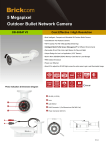
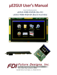
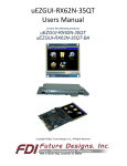
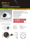
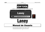
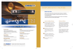
µEZGUI User’s Manual Covers the following products: uEZGUI-EXP1 Copyright ©2014, Future Designs, Inc., All Rights Reserved Table of Contents Introduction _________________________________________________________________ Functional Description _________________________________________________________ Expansion Board Capabilities ____________________________________________________ Orderable part numbers ________________________________________________________ Expansion Connector __________________________________________________________ Expansion Connector Cable Details _______________________________________________ DC Power Input – P4 ___________________________________________________________ USB Device – P1 ______________________________________________________________ USB Host – P2 ________________________________________________________________ Ethernet – J2 _________________________________________________________________ Supported uEZGUIs ____________________________________________________________ Serial Port – P3 _______________________________________________________________ Example Connections to the uEZGUI Boards ________________________________________ Information in this document is provided solely to enable the use of Future Designs products. FDI assumes no liability whatsoever, including infringement of any patent or copyright. FDI reserves the right to make changes to these specifications at any time, without notice. No part of this document may be reproduced or transmitted in any form or by any means, electronic or mechanical, for any purpose, without the express written permission of Future Designs, Inc. 996 A Cleaner Way, Huntsville, AL 35805. For more information on FDI or our products please visit www.teamfdi.com. NOTE: The inclusion of vendor software products in this kit does not imply an endorsement of the product by Future Designs, Inc. 2014 Future Designs, Inc. All rights reserved. uEZ® is a registered trademark of Future Designs, Inc. Other brand names are trademarks or registered trademarks of their respective owners. FDI PN: MA00030 Revision: 2.0, 08/13/2014 Printed in the United States of America 1 1 1 1 1 3 3 3 4 4 4 5 5 Introduction The uEZGUI-EXP1 is a quick and easy solution for adding additional hardware to the uEZGUI family of products. The uEZGUI-EXP1 offers the hardware necessary for USB Host and Device, Ethernet, RS232, and RS485. Functional Description RS232/RS485 Serial communication USB Host and Device 10/100 Ethernet Expansion Board Capabilities The uEZGUI Expansion Board enhances the capabilities of the standard uEZGUI board to include additional IO capabilities. The Expansion Board is connected to the uEZGUI main board via a 50pin FPC cable. Orderable part numbers The uEZGUI-EXP1 is available by itself, or as part of the uEZGUI-43-H01 production module. Please see FDI’s website for the latest purchasing and distributor information. Expansion Connector FDI’s uEZGUIs include a 50 pin FPC Expansion Connector that provides a wide variety of capabilities for user expansion, ranging from 10/100 Ethernet to USB Host, etc. The part number used for the FPC connector is OMRON XF2M-5015-1A. The table below provides the pin out and signal used on the uEZGUI-EXP1: (see the corresponding uEZGUI schematics for the up-to-date listings of all pin capabilities) 1 Pin # 1–2 3–5 Pin Name 3p3 volts (3V3) 5volts (5V0) 6 USBD_VBUS 7 8 9 10 USBD_DM USBD_DP P0.2_TXD0 P0.3_RXD0 11 ISP_ENTRY 12 13 14 15 GND P1.0_ENET_TXD0 P1.1_ENET_TXD1 P1.4_ENET_TXEN 16 P1.8_ENET_CRSDV 17 18 19 20 P1.9_ENET_RXD0 P1.10_ENET_RXD1 3p3 volts (3V3) P1.14_ENET_RX_ER 21 P1.15_ENET_REFCLK 22 23 24 25 26 27 GND P1.16_ENET_MDC P1.17_ENET_MDIO 28 RESET_IN 29 30 31 32 33 34 35 36 37 38 39 40 41 42 43 44 45 46 47 48 49 50 GND RESET_OUT USB1H_PPWR USB1H_OVC USB1H_PWRD USB1_DP USB1_DM GND P0.15_TXD1 P0.16_RXD1 P0.17_CTS1 P0.22_RTS1 GND Pin Description 3.3 Volts DC Input to EXP1 from uEZGUI 5.0 Volts DC Output to uEZGUI VBUS – Monitors the presence of USB bus power. Note: Must be HIGH for USB reset to occur. (USB Device port on uEZGUI-EXP1) USB_D-2 – USB port 2 bidirectional D –line (USB Device port on uEZGUI-EXP1) USB_D+2 – USB port 2 bidirectional D+ line (USB Device port on uEZGUI-EXP1) TXD0 – Transmitter output for UART0. (for RS232) RXD0 – Receiver input for UART0. (for RS232) I/O – P2[10] – General purpose digital input/output pin. Note: LOW on this pin on NXP LPCXXXX while RESET is LOW forces on-chip boot loader to take over control of the part after a reset. Ground ENET_TXD0 – Ethernet transmit data 0 (RMII/MII interface) ENET_TXD1 – Ethernet transmit data 1 (RMII/MII interface) ENET_TX_EN – Ethernet transmit data enable (RMII/MII interface) ENET_CRS_DV/ENET_CRS – Ethernet Carrier Sense/Data Valid (RMII interface)/ Ethernet Carrier Sense (MII interface) ENET_RXD0 – Ethernet receive data 0 (RMII/MII interface) ENET_RXD1 – Ethernet receive data 1 (RMII/MII interface) 3.3 Volts DC Input to EXP1 from uEZGUI ENET_RX_ER – Ethernet receive error (RMII/MII interface) ENET_REF_CLK/ENET_RX_CLK – Ethernet Reference Clock (RMII interface)/ Ethernet Receive Clock (MII interface) Ground ENET_MDC – Ethernet MIIM clock ENET_MDIO – Ethernet MIIM data input and Output Unused Unused RSTOUT – This is a 3.3 V pin. LOW on this pin indicates LPC1788 being in Reset state External reset input: A LOW on this pin resets the device, causing I/O ports and peripherals to take on their default states, and processor execution to begin at address 0. TTL with hysteresis Ground Unused Unused Unused Unused Unused Unused USB_PPWR1 – Port Power enable signal for USB port 1. (USB Host port on uEZGUI-EXP1) USB_OVC – Overcurrent detection (USB Host port on uEZGUI-EXP1) USB_PWRD – 5V power detection (USB Host port on uEZGUI-EXP1) USB_D+1 – USB port 1 bidirectional D+ line. (USB Host port on uEZGUI-EXP1) USB_D-1 – USB port 1 bidirectional D--line. (USB Host port on uEZGUI-EXP1) Ground TXD1 – Transmitter output for UART1. (for RS485) RXD1 – Receiver input for UART1. (for RS485) CTS1 – Clear to Send input for UART1. (for RS485) RTS1 – Request to Send output for UART1. (for RS485) Unused Unused Unused Unused Ground 2 Input/output Power Power Input Input / Output Input / Output Output Input Input / Output Power Output Output Output Input Input Input Power Input Input Power Output Input / Output Output Input Power Output Input Input Input / Output Input / Output Power Output Input Input Output Power Expansion Connector Cable Details The maximum length for the expansion connector cables is as follows: General Purpose IO, TTL, Serial, etc = 6” recommended maximum, 8” absolute maximum Ethernet, high-speed IO, etc = 3” recommended maximum, 4” absolute maximum The following table provides example part numbers for the expansion cables: Description Mfg Mfg PN 3” 50-pin 0.5mm Molex 21020-7650 6” 50-pin 0.5mm Molex 21020-0548 Digi-Key Pn WM10231-ND WM10223-ND Note: These lengths are only recommendations. The actual lengths utilized will be dependent on the expansion board circuitry, layouts and general environment of the application. It is up to the customer to test and validate the functional operation and use of the expansion connectors. DC Power Input – P4 The uEZGUI-EXP1 supports a 7VDC-24VDC 1A (min) Power Supply. The connector is 2.1mm with center positive. Pin Number Description 1 7VDC to 24VDC, +/- 10%, 1.0A (min) 2 Power Supply Ground USB Device – P1 The UEZGUI-EXP1 Board includes one USB Device Interface allowing the unit to be connected to a USB Host, such as a PC. Through this connection, the uEZGUI represents a peripheral to the USB Host. The operational mode of the port is dependent on the software utilized (i.e. Mass Storage or Human-Interface). Note: The USB Device connector of the Expansion Board is connected in parallel to the USB Device connector of the uEZGUI Main board. To avoid damage or improper operation, do not connect both of these at the same time. The UEZGUI-EXP1 Board may also be powered via the USB Device connector. Care must be taken to not overload the USB Host since 500mA is the maximum current allowable via USB. Pin Number 1 2 3 4 5 3 Description USB 5V DD+ NC Signal Ground USB Host – P2 The uEZGUI-EXP1 Board includes one USB Host Port allowing the unit to interface to various USB peripherals such as a USB Flash Drive (Thumb Drive). The operational mode of this port is dependent on the software utilized (i.e. driver support) Pin Number Description 1 USB VBus 2 D- 3 D+ 4 Signal Ground Ethernet – J2 The UEZGUI-EXP1 Board includes one 10/100 Ethernet Port to interface to a local area network via CAT5 cable. Please refer to the specific details of the LPC1788 processor being utilized for support of the Ethernet Port function. Pin Number 1 2 3 4 5 6 7 8 Supported uEZGUIs The uEZGUI-EXP1 is currently supported on the following uEZGUIs: uEZGUI-1788-43WQR uEZGUI-4088-43WQN uEZGUI-1788-70WVT uEZGUI-1788-70WVM uEZGUI-1788-56VI uEZGUI-RX62N-35QT 4 Description Tx+ TxRx+ 75 ohm terminated 75 ohm terminated Rx75 ohm terminated 75 ohm terminated Serial Port – P3 The uEZGUI-EXP1 Board includes one female DB9 Serial Port Connector. This connector may operate in either RS232 or RS485 (Full-duplex) interface levels depending on jumper settings of JP1 through JP4. Jumpers JP1 – JP4 select the operating mode of the serial port; Jumper 1-2 for RS232 levels, using UART0 Jumper 2-3 for RS485 levels, using UART1 When operating as RS232, the serial port may also be optionally configured to support ISP programming of the LPC1788 using FlashMagic Software. To enable ISP programming, jumper JP6 & JP7 must be loaded. Note that with these jumpers loaded, operation of the LPC1788 may be affected by the RS232 interface signals. Refer to the FlashMagic user manual for details. Pin Number 1 2 3 4 5 6 7 8 9 RS485 Mode No Connect 485_RDB485_TDA+ Signal Ground Signal Ground Signal Ground 485_RDA+ 485_TDB(OPT 5V) RS232 Mode No Connect TXD (Output) RXD (Input) No Connect Signal Ground Signal Ground (OPT) RTS (OPT) CTS No Connect Example Connections to the uEZGUI Boards uEZGUI-1788-43WQR example connection with uEZGUI-EXP1 5 uEZGUI-1788-70WVT example connection with uEZGUI-EXP1 uEZGUI-43-H01 production module: uEZGUI-1788-43WQR with uEZGUI-EXP1 mounted in OEM Housing 6