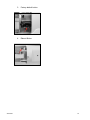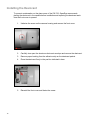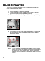
1
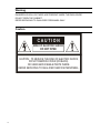
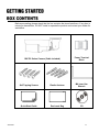
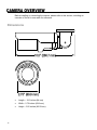
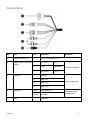
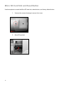
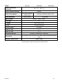
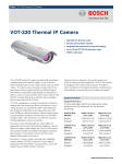
2MP Outdoor IR IP Bullet Camera User Manual Camera CM-722I CM-722AI CM-722VF www.openeye.net 2MP IR IP Bullet Camera (CM-722 Series) User Manual Manual Edition 31051AD – APRIL 2015 ©2015, OPENEYE All Rights Reserved. No part of this documentation may be reproduced in any means, electronic or mechanical, for any purpose, except as expressed in the Software License Agreement. OpenEye shall not be liable for technical or editorial errors or omissions contained herein. The information in this document is subject to change without notice. The information in this publication is provided “as is” without warranty of any kind. The entire risk arising out of the use of this information remains with recipient. In no event shall OPENEYE be liable for any direct, consequential, incidental, special, punitive, or other damages whatsoever (including without limitation, damages for loss of business profits, business interruption or loss of business information), even if OPENEYE has been advised of the possibility of such damages and whether in an action or contract or tort, including negligence. This documentation is copyrighted. All other rights are reserved to OPENEYE. OPENEYE, and OpenEye, are registered trademarks of OPENEYE in the United States and elsewhere; Windows, and Windows XP Embedded are registered trademarks of Microsoft Corporation. All other brand and product names are trademarks or registered trademarks of the respective owners. OPENEYE Liberty Lake, WA ● U.S.A. 31051AD 3 Important Safeguards 1. Read Instructions Read all of the safety and operating instructions before using the product. 2. Retain Instructions Save these instructions for future reference. 3. Attachments / Accessories Do not use attachments or accessories unless recommended by the appliance manufacturer as they may cause hazards, damage product and void warranty. 4. Installation Do not place or mount this product in or on an unstable or improperly supported location. Improperly installed product may fall, causing serious injury to a child or adult, and damage to the product. Use only with a mounting device recommended by the manufacturer, or sold with the product. To insure proper mounting, follow the manufacturer's instructions and use only mounting accessories recommended by manufacturer. 5. Power source This product should be operated only from the type of power source indicated on the marking label. Precautions Operating Before using, make sure power supply and others are properly connected. While operating, if any abnormal condition or malfunction is observed, stop using the camera immediately and then contact your local dealer. Handling 4 Do not disassemble or tamper with parts inside the camera. Do not drop or subject the camera to shock and vibration as this can damage camera. Do not block the cooling holes on the bracket. This camera has a cooling fan inside the housing. Blocking the cooling holes will cause heat to build up and cause malfunction. Care must be taken when you clean the clear dome cover. Scratches and dust will ruin the image quality of your camera. Do not use strong or abrasive detergents when cleaning the camera body. Use a dry cloth to clean the camera when it is dirty. In case the dirt is hard to remove, use a mild detergent and wipe the camera gently. Installation and Storage Install electricity wiring carefully. Please note that input electricity to the unit is at tolerance of DC 12V/AC 24V ± 10%. The camera is capable of surge protection; ensure AC power model unit is grounded appropriately against damage by heavy current or electric shock. Do not install the camera in areas of extreme temperatures in excess of the allowable range. ( -40°F ~ 122°F / -40°C ~ 50°C) Avoid installing in humid or dusty places. The relative humidity must be below 90%. Avoid installing in places where radiation is present. Avoid installing in places where there are strong magnetic fields and electric signals. Avoid installing in places where the camera would be subject to strong vibrations. Never face the camera toward the sun. Do not aim at bright objects. Whether the camera is in use or not, never aim it at the sun or other extremely bright objects. Otherwise the camera may be smeared and damaged. Regulation This device complies with Part 15 of the FCC Rules. Operation is subject to the following two conditions: (1) this device may not cause harmful interference, and (2) this device must accept any interference received, including interference that may cause undesired operation. This symbol on the product or on its packaging indicates that this product shall not be treated as household waste in accordance with Directive 2002/96/EC. Instead it shall be handed over to the applicable collection point for the recycling of electrical and electronic equipment. By proper waste handling of this product you ensure that it has no negative consequences for the environment and human health, which could otherwise be caused if this product is thrown into the garbage bin. The recycling of materials will help to conserve natural resources. For more details information about recycling of this product, please contact your local city office, your household waste disposal service or the shop where you purchased the product. Compliance is evidenced by written declaration from our suppliers, assuring that any potential trace contamination levels of restricted substances are below the maximum level set by EU Directive 2002/95/EC, or are exempted due to their application. 31051AD 5 Warning DANGEROUS HIGH VOLTAGES ARE PRESENT INSIDE THE ENCLOSURE. DO NOT OPEN THE CABINET. REFER SERVICING TO QUALIFIED PERSONNEL ONLY. Caution CAUTION RISK OF ELECTRIC SHOCK DO NOT OPEN CAUTION: TO REDUCE THE RISK OF ELECTRIC SHOCK, DO NOT REMOVE COVER (OR BACK). NO USER-SERVICEABLE PARTS INSIDE. REFER SERVICING TO QUALIFIED SERVICE PERSONNEL. 6 Introduction ............................................................................................ 10 Overview ....................................................................................................................... 10 Product Features ...................................................................................................... 10 Getting Started ....................................................................................... 11 Box Contents ................................................................................................................ 11 Camera Overview ......................................................................................................... 12 Dimensions ............................................................................................................... 12 Connections .............................................................................................................. 13 Micro SD Card Slot and Reset Button ...................................................................... 14 Installing the Desiccant ............................................................................................. 16 Installation .............................................................................................. 17 Power and Ethernet Connection ................................................................................... 17 Power Connection .................................................................................................... 17 Ethernet Cable Connection ...................................................................................... 17 Ceiling Installation ......................................................................................................... 18 Lens Adjustment ........................................................................................................... 19 Setup and Configuration ....................................................................... 20 OpenEye Network Camera manager ........................................................................... 20 Installation................................................................................................................. 20 Starting Network Camera Manager .......................................................................... 20 Camera Configuration ................................................................................................... 21 Device Addressing .................................................................................................... 21 Finding Network Devices ..................................................................................... 21 Viewing a Network Camera.................................................................................. 22 Connecting to the Camera........................................................................................ 23 Resetting the Camera .......................................................................................... 23 Administrator/User Privileges ............................................................................... 23 Connecting Over the Internet ............................................................................... 24 Viewer Software ............................................................................................................ 25 Viewer Tabs .............................................................................................................. 25 31051AD 7 Live .......................................................................................................... 26 Setup ....................................................................................................... 27 System Setting .............................................................................................................. 27 Camera Name .......................................................................................................... 27 IP Address ................................................................................................................ 28 Get IP an Address Automatically (DHCP) ............................................................ 28 Use Static IP Address .......................................................................................... 29 IPv6 Address Configuration ............................................................................. 29 User Setup ................................................................................................................ 30 Admin Password .................................................................................................. 30 Add User .............................................................................................................. 30 Delete User .......................................................................................................... 30 Modify User .......................................................................................................... 31 File Location ............................................................................................................. 31 Picture Setup ................................................................................................................ 31 Camera Tab .............................................................................................................. 31 Exposure .............................................................................................................. 32 White Balance ...................................................................................................... 32 Picture Adjustment ............................................................................................... 33 Motion Detection ....................................................................................................... 33 Add Detection Window ......................................................................................... 34 Delete Motion Detection Window ......................................................................... 34 Motion Window ................................................................................................ 34 Streaming Settings ....................................................................................................... 35 Video Resolution ...................................................................................................... 35 Video Orientation ................................................................................................. 36 GOP Size ............................................................................................................. 36 H.264 Profile ........................................................................................................ 36 Video Frame Rate .................................................................................................... 37 Video Compression .................................................................................................. 38 Advanced ................................................................................................ 39 System Setting .............................................................................................................. 39 Network Setup .......................................................................................................... 39 DDNS ................................................................................................................... 39 8 Network Advanced ................................................................................................... 39 QoS ...................................................................................................................... 39 SNMP Settings ..................................................................................................... 40 UPnP (Universal Plug N’ Play) ............................................................................. 40 Network Security ...................................................................................................... 41 HTTP .................................................................................................................... 41 IP Filtering ............................................................................................................ 41 IEEE 802.1XSEAP-TLS ....................................................................................... 41 Alarm Application ...................................................................................................... 42 Tampering and Network Failure Detection ............................................................... 43 Mail, HTTP and FTP Setup ...................................................................................... 44 SD Card .................................................................................................................... 44 Network Share .......................................................................................................... 45 Recording Schedule ................................................................................................. 46 Recording ............................................................................................................. 46 Schedule .............................................................................................................. 47 Interval Recording ................................................................................................ 48 Maintenance ............................................................................................................. 49 Configuration ........................................................................................................ 49 Factory Default ..................................................................................................... 49 Software.................................................................................................................... 50 Picture Setting .............................................................................................................. 50 Video Mask ............................................................................................................... 50 Hot Spot .................................................................................................................... 50 Text Overlay ............................................................................................................. 50 Streaming Setting ......................................................................................................... 51 Audio ......................................................................................................................... 51 Logout ..................................................................................................... 51 Specifications......................................................................................... 52 Camera Specifications .................................................................................................. 52 Appendix A ............................................................................................. 54 Set Up Internet Security................................................................................................ 54 Setting Internet Security Level to Default ................................................................. 54 Adjusting ActiveX Controls and Plug-ins .................................................................. 55 31051AD 9 The OpenEye CM-722 series is a collection of 2MP outdoor IP bullet cameras built to provide superior video quality. All CM-722 cameras utilize MJPEG or H.264 compression to provide video at resolutions up to 1080p (2MP) and are capable of dual and quad streaming at 720p (1MP). Each camera in the CM-722 series is equipped with 23 IR LEDs and a mechanical IR cut filter for true day/night operation, allowing the camera to record high-resolution images at 0 Lux. The CM-722I is equipped with all the standard features of the CM-722 line, while the CM722AI includes a motorized lens and the CM-722VF includes a varifocal lens. The CM-722 series is designed to operate in extreme conditions in a tamper-resistant housing. It is equipped with an integrated heater, allowing operation in temperatures as low as -40°F (-40°C). CM-722 cameras can be powered via 24vAC, 12vDC, or a PoE switch. 24vAC power is required to operate the on-board heater. Product Features 10 ONVIF™ compliant H.264 / MJPEG quad streaming 2MP resolution (1080p HD) IP66 weatherproof rating True Day/Night On-board heater 23 IR LEDs Before proceeding, please check that the box contains the items listed here. If any item is missing or has defects, DO NOT install or operate the product and contact your dealer for assistance. CM-722 Series Camera (Cable included) 31051AD Power Terminal Block Self Tapping Screws Plastic Anchors M4 Inner Hex Wrench Quick Start Guide Desiccant Bag CD 11 Before installing or connecting the camera, please refer to this section, including an overview of the all-in-one cable for reference. Dimensions 12 Length – 10.5 inches (84 mm) Width – 2.75 inches (69.9 mm) Height – 3.25 inches (82.55 mm) Connections No. Item Pin Definition 1 Network (with PoE) - RJ-45 connector w/ LED 2 Power (3-pin Terminal Block) 1 AC 24V-1 DC (-) 2 GND Reserved 3 AC 24V-2 DC (+) 1 ALM_DI- 2 ALM_DI+ 3 ALM_DO- 4 ALM_DO+ Pink Line In/Mic In Green Line Out - Video out 3 Alarm I/O Remarks Power connection Alarm connection 4 5 31051AD Audio I/O BNC Two-way audio transmission 13 Micro SD Card Slot and Reset Button Use these photos to reach the Micro SD card slot, reboot button, and factory default button. 14 1. Unscrew the camera housing to remove front cover. 2. Micro SD card slot 31051AD 3. Factory default button 4. Reboot Button 15 Installing the Desiccant To prevent condensation on the glass cover of the CM-722, OpenEye recommends placing the desiccant in the camera before installation and replacing the desiccant each time the front cover is opened. 16 1. Unfasten the screw on the camera housing and remove the front cover 2. Carefully tear open the aluminum desiccant envelope and remove the desiccant. 3. Remove paper backing from the adhesive strip on the desiccant packet. 4. Place the desiccant firmly in the position indicated in here. 5. Reinstall the front cover and fasten the screw. Read the installation instructions before installing and connecting the IP camera. Power Connection Make sure that the camera’s power cable is correctly and firmly connected. OpenEye recommends against using more than one power source at a time. Do not use a PoE power source when providing the camera with 12vDC or 24vAC power. Make sure the camera’s power cable is correctly and firmly connected. If using Power over Ethernet (PoE), make sure Power Sourcing Equipment (PSE) is in use in the network. Ethernet Cable Connection OpenEye recommends using Category 5 Ethernet cable to connect the camera to your network. For the best transmission quality, the cable length should not exceed 328 feet (100 meters). Connect a network cable to the camera using the RJ45 input and connect the other end of the cable to your network switch or recorder. If you are connecting the camera directly to a recorder, a crossover cable is necessary for most configurations. Check the status of the network connection by looking at the link indicator and activity indicator LEDs. If the LEDs are not lit check your network connection. The green link LED indicates a network connection and the orange activity LED flashes to indicate network activity. 31051AD 17 The IR Bullet IP Camera can be installed directly on a wall or ceiling provided it has enough strength to support the camera. 1. Remove the IR Bullet IP Camera from packaging 2. Connect power, Ethernet, Alarm and audio wires from ceiling or wall to the corresponding connectors of the cameras all-in-one cable. 3. Fix the camera’s bracket on the ceiling or wall with the three supplied self-tapping screws. 4. Use the supplied inner hex wrench and a Phillips screwdriver to loosen the hex bolt on the side of the bracket mount and the camera housing to adjust the position of the camera. CM-722 cameras are equipped with a seal inside the housing to prevent moisture from entering. If you have any concerns about moisture entering the housing or wall through the cable egress , OpenEye recommends sealing the opening at the wall and at the base of the camera with silicone caulking. 18 31051AD 1. Unscrew the camera housing to remove front housing. 2. Connect the power, audio, and alarm wires to their corresponding connectors. (Refer to the pin definition table.) 3. Access the camera browser in order to view images. 4. Adjust the zoom/focus ring screw on the lens to set the desired zoom and focal length. 5. Replace front housing and tighten screw. 19 OpenEye Network Camera Manager is a software tool that allows you to quickly and easily connect and configure your OpenEye IP Cameras. This software allows you to assign IP addresses, manage users, configure video settings, and update firmware on multiple cameras at once. The Network Camera Manager software is pre-installed on all OpenEye Recorders, and included on the software CD with all OpenEye IP cameras. It is also available for download on the OpenEye website. Installation You can install Network Camera Manager on any personal computer (PC) or laptop using the software CD included with your OpenEye IP camera or by downloading the program from openeye.net. Network Camera Manager will only work on PCs or laptops that use a Windows operating system. It is compatible with Windows XP, Vista, 7, and 8. Starting Network Camera Manager After installing the program on your PC or laptop, open the program to begin configuring your cameras. To access Network Camera Manager on an OpenEye recorder, you must operate the recorder in Windows Mode. 20 1. In the Live Screen, click Exit. 2. Click Restart in Windows Mode. 3. Click OK. 4. Double-click Network Camera Manager. Device Addressing The functions on the Device Addressing tab allow you to find, configure, and view network cameras. 31051AD 1. Click Find Devices on the Device Addressing tab. 2. To narrow your search by Camera Model, Project, or Camera Name, select your desired criteria from the appropriate lists. 21 1. To view a network camera over the web using the camera’s viewer software, double-click the name of the camera. 2. Click Browse. 3. Enter the Username and Password for the camera. The username and password are case sensitive. It is strongly recommended that the password be changed after the initial setup to prevent unauthorized access. The default username and password for OpenEye IP cameras are as follows. Username – Admin Password – 1234 4. The viewer software is now opened in Internet Explorer. The viewer software will install automatically the first time you connect to the camera. If your internet browser does not install the viewer software, check the security settings or ActiveX controls and plug-in settings. If your internet browser asks for permission to install the ActiveX control, you must allow the ActiveX control to continue the installation. If you are prompted to allow an add-on, click Allow. 5. 22 You can now configure your camera using the Viewer Software. For more information on using Viewer software, please see the user manual for your camera. Connecting to the Camera 1. Locate the camera on the IP Finder list. 2. Double-click the camera to open the Viewer software in your web browser. 3. Click Browse in the pop-up window. 4. Log in to the camera with the appropriate User Name and Password. The default User name is admin and the default Password is1234. The username and password are case sensitive. If it is necessary to reset the camera to the factory default settings, hold down the Reset button (see Camera Overview) for 30 seconds. This will return all settings, including network setup, to the factory default. The Administrator account has the authority to configure the IP camera and authorize users’ access to the camera. The User accounts have access to the camera with limited authority. 31051AD 23 There are some challenges with connecting to OpenEye IP cameras over WAN (internet) connections because the camera streams video over RTSP. RTSP is an excellent protocol for media and is now used on many IP cameras (including OpenEye) as the default streaming option. RTSP, however, is not suitable for transmission between two locations that are behind different routers. In this case, the client (for example, the OpenEye HVR or NVR server software) connects to the camera, and then requests a stream. The camera uses that connection to return a stream, but since the connection originated on the client side and has now switched to the camera (remote) side, the router does not have any way to determine where the traffic should be routed, so no video appears at the recorder. There are three solutions to this. 1. Connect modems on both sides directly to the recorder and camera. If there is no router, no network address translation is needed. 2. Use routers with VPN support and set up a small VPN. Once this is done, the traffic will be treated as though it were all on the local network. 3. (Best solution) – Use routers with connection tracking. This is quite easy; VOIP also uses RTSP and faces the same challenges. If a router is marketed as having “VOIP Support”, it will have the necessary connection tracking capability to allow any type of RTSP communication (not just VOIP). With proper planning and the correct equipment, RTSP cameras CAN stream over the WAN to a recording device for minimal additional cost and labor. Please contact OpenEye support if you require any additional information on these topics. 24 To access the setup menu, you need to install the viewer software on your PC or recorder. The viewer software will install automatically the first time you connect to the camera. If your internet browser doesn’t install the viewer software, check the security settings or ActiveX controls and plug-in settings. If your internet browser asks for permission to install the ActiveX control, you must allow the ActiveX control to continue the installation. The first time you connect to a camera, the browser will ask for permission to install the ActiveX Control necessary to display the camera video. Right-click the information bar and click Install ActiveX Control to allow the installation. IP camera audio is only available on the Indoor IP mini dome camera. The Talk button will not be available on the Outdoor version of the camera. Viewer Tabs Live – Monitor video and perform other video related functions. Setup – Set the camera name, IP address, and define users. This tab also allows you to configure the camera settings and view streams. Advanced – Perform advanced setup configurations, like network setup, security, alarms and maintenance. Logout – Change user. 31051AD 25 Full Screen – This will display the live feed in full screen. Snapshot – Click the button, and a JPEG snapshot will automatically be saved in the appointed place. The default location is: C:\. If you are using Windows Vista or 7, you will need to change the Snapshot location. Windows UAC does not allow internet programs to write directly to C:\ for security reasons. Record – Click Record to star recording live video. Click Record again to stop recording video. Recorded video will be saved automatically to the designated location on the local workstation. The default location is C:/. This location can be changed in File Location, in the System menu. If you are using Windows Vista or 7, you will need to change the video clip location. Windows UAC does not allow internet programs to write directly to C:\ for security reasons. Microphone – PC Network Camera Manager Software audio to camera, enables audio through an audio out on the camera. Live Audio – Camera to PC Network Camera Manager Software, enables audio if a microphone is equipped to the camera. The Microphone and Live Audio functions are only available on enable cameras. If the camera is not enabled for these features, an error message will display. 26 The Setup menu includes System Settings, Picture Setup, and Streaming Settings. The Setup menu displays limited setup options. For a complete list of setup options, see the Advanced section. Camera Name Host Name – The Host Name is used to identify the camera on your system. If camera based Motion Detection is enabled and is set to send alarm message by Mail/FTP, the host name entered here will display in the alarm message. Time Zone – Select your time zone. Time Format – Select your desired time format. Sync With Computer Time – Select to synchronize the camera date and time with the connected recorder. Sync with NTP Server – Manual allows you to define the date and time manually. Network Time Protocol (NTP) is an alternate way to synchronize your camera’s clock with a NTP server. Specify the server you wish to synchronize in the NTP Server box. Then select an Update Interval. For more information about NTP, visit www.ntp.org. 31051AD 27 IP Address You can choose to use a fixed IP address or a dynamic IP address (assigned by a DHCP server or router) for the camera. The camera comes preconfigured with a fixed IP address, selecting Get IP address automatically requires a router or DHCP server to assign an IP address to the camera. Every network device has a unique Media Access Control (MAC) address that can be used for identification. The MAC address is located on the bottom of each camera, and on the box label (OpenEye Network Camera Manager also displays the MAC address for identification). Record your camera’s MAC address for identification in the future. 28 To set up a new static IP address: 1. Select the Use static IP address option. 2. Type a new IP address in the IP address box. 3. Type a new address in the Default Gateway box. 4. Click Apply to confirm the new setting. When using static IP address to log in to the IP Camera, you can access it either through OpenEye IP Finder software or type the IP address directly in the address bar of your Internet Explorer. IP Address – The IP Address is necessary for network identification. Subnet mask – Used to determine if the destination is in the same subnet. The default value is 255.255.255.0. Default gateway – Used to forward frames to destinations on different subnets or for internet access. Primary DNS – The primary domain name server that translates hostnames into IP addresses. Secondary DNS – A secondary domain name server that backups the primary DNS. Web Server port – Defines the port that Internet Explorer uses to connect over the web and view video. If this port is changed then the new port must be defined when attempting to web connect (ex: if your camera’s IP address is 192.168.0.100 and you change the web port to 8001, then you must type http://192.168.0.100:8001 in your browser). RTSP port – The default RTSP port is 554; setting range: 1024 ~65535. MJPEG over HTTP port – The default HTTP Port is 8008; setting range: 1024 ~65535. HTTPS port – The default HTTPS Port is 443; setting range: 1024 ~65535. No port number can be used in duplication on more than one item. IPv6 Address Configuration To enable IPv6 select Enable IPv6 and click Save. See your network administrator if you are unsure of your network configuration. 31051AD 29 User Setup Manage the password for the Administrator account. To change the administrator password: 1. Type a new Administrator Password, and then type again to confirm the password. 2. Click Save. The user name and passwords are limited to 16 characters with no spaces permitted. There is a maximum of twenty user accounts. 1. Type the new Username and Password. 2. Select I/O Access, Camera Control, Talk, and/or Listen as permissions for the User. I/O Access – All functions in the Setup and Advanced menus are available to the User. Camera Control– Allows the User to change camera controls in the Setup menu. Talk – Allow the user to speak through the camera microphone. Listen – Allow the user to listen to audio captured by the camera. 3. Click Add. 1. Select the user name on the User Name list. 2. Click Delete to remove the user. 3. Click OK in the confirmation window. There is a momentary wait time while the Network Camera Manager saves parameters. When this period is complete, the User will be deleted. 30 1. Select the user name on the User Name list. 2. Click Edit. 3. In the resulting window, modify the Password and/or feature permissions. 4. Click Save. For security reasons, every time the user properties are opened the access check boxes are automatically cleared. Make sure you select any user access options each time you edit the user properties. File Location This is the destination location that snapshot photos and recorded videos will be saved to. To select a destination location: 1. Click Select. 2. Choose a location or folder. 3. Click Save in the file window, and then click Save again. Camera Tab Use the Camera Tab section to modify picture settings for the camera. The sample image will change as you modify the picture settings. These settings can drastically affect the camera image. OpenEye suggests that these settings are only modified by a CCTV professional, or at the instruction or a technical support representative. 31051AD 31 Min Shutter Speed – Choose a pre-determined shutter speed. Manual Mode – Changing the shutter mode to manual will allow you to select the minimum shutter speed that the camera will use. This can drastically change the amount of light entering the camera. Click Set to save your changes. Use the white balance setting to change color representation in difficult lighting conditions. Auto – White balance works within its color temperature range and calculates the best-fit white balance. ATW – Auto-tracing white balance, the camera removes the signals within a range of 2000K to 10000K, which helps to even out the bright white portions of an image. One Push – Balances color temperature based on a white object within the viewing area. Manual – Change the white balance value by specifying the R grain and B grain. Click Set to save your changes. 32 Each of the Picture Adjustment settings is set to the recommended default. Brightness – Adjust the image’s brightness on the camera. The Backlight value is adjustable from 0 (dim) ~ +20 (brightest). Sharpness – Increasing the sharpness level can make the image looked sharper; it especially enhances an object’s edge. The value of sharpness is adjustable from 0 ~ +10 (sharpest). Contrast– Adjust the contrast value from -6 to 19. Saturation– Adjust the color saturation form -6 to 19 (most saturation). Hue– Adjust the hue from -12 to 13. Backlight– Backlight compensation can correct for overly-bright backlit scenaries. D-WDR Function– Turn the Digital Wide Dynamic Range Off, or adjust between 1 and 3. Click Set after making changes to the Picture Adjustment settings to save the settings and update the Live screen. Motion Detection Use the Motion Detection menu to configure the motion detection window(s). Here, Motion Detection can be turned On or Off, and other general settings can be specified. To enable motion detection: 1. Use the Motion Detection dropdown to select a motion detection preset (1-4). If choosing an additional preset after 1, check the On checkbox. A motion detection preset can be turned Off at a later time. 31051AD 2. If desired, check the By Schedule check box and use the dropdown menu to select a schedule. 3. Designate the Motion Detection Setting values. 4. Check the appropriate boxes to designate the Trigger Action. 5. Click Save. 33 1. Use the Motion Detection dropdown to select a motion detection preset. 2. Click Add. The selected motion detection square will be red. 3. Arrange and size the motion detection window as desired. 4. Click Save. 1. Click to select the desired motion detection window. 2. Click Delete. Motion Window The motion window displays a red line and a dynamic blue line. The red line represents the Detection Level. The blue line will also be present if motion is present in the camera frame. The blue line will react accordingly based on the motion in the camera frame. 34 Video Resolution The camera provides eight codec options under video resolution (two single streaming options, two sets of dual streaming options, two sets of tristreaming options, and two sets of quad-streaming options): H.264 Only MJPEG Only H.264 + H.264 H.264 + MJPEG H.264 + H.264 + H.264 H.264 + H.264 + MJPEG H.264 + H.264 + H.264 + H.264 H.264 + H.264 + H.264 + MJPEG Once a codec option is selected, multiple resolutions are available for each stream. Due to resource management, some resolutions may be unavailable when selecting a dual stream option. 31051AD 35 Normal Video – The video will be oriented as the camera position dictates. 180 Degree Rotate – Rotate the video 180 degrees. 90 Degree Clockwise – Rotate the video 90 degrees clockwise. 90 Degree Counter Clockwise– Rotate the video 90 degrees counter clockwise. Mirror Video – Flip the video across the vertical axis. Mirror + 180 Degree Rotate – Flip the video across the vertical axis and rotate 180 degrees. The Group of Pictures settings allow you to modify the frame structure of the video stream. This setting changes the frequency of the I-frames that occur within the stream of P-frames (2~64). Increasing this number increases the number of P-frames between each I-frame; decreasing the file size of the stream, but increasing the risk of video decoding errors. Decreasing this number decreases the number of P-Frames between each I-frame; increasing the file size of the stream, but decreasing the risk of video decoding errors. OpenEye recommends setting the GOP to be approximately twice the frame rate (e.g.: if the frame rate is 10 IPS, then set the GOP to 20). The H.264 Profile may need to be changed if you are using a third party recorder that is not capable of decoding H.264 Main Profile video compression. Select compatible compression type for each stream if necessary. 36 Video Frame Rate Setting the camera to transmit fewer frames can save bandwidth. Use the Frame Rate Control screen to adjust the frame rate of each stream. Each of the MJPEG and H.264 streams can have a separate frame rate setting from 1 to 30 frames per second. Higher frame rate will increase video smoothness, as well as file size and bandwidth usage. Lower frame rate will decrease video smoothness, as well as file size and bandwidth usage. 31051AD 37 Video Compression You can select an MJPEG / H.264 compression mode on the video compression page appropriate for your application. You can also select to display compression inflation on the Live Screen. MJPEG compression settings include: High compression, low bitrate, low quality Middle compression, default Low compression, high bitrate, high quality H.264 compression settings include: 1024kbps, highest compression, lowest quality 2048kbps 4096kbps, middle compression, default 6144kbps 8192kbps, low compression, highest quality CBR Mode Setting 38 The Constant Bit Rate mode allows you to lock in the bit rate of the H.264 stream. If this setting is not enabled, bit rate may fluctuate based on available bandwidth. Network Setup The Network Setup settings will automatically be set at the recommended default after the camera connection is made. DDNS (Dynamic Domain Name Service) is a service that allows a connection to an IP address using a hostname (URL) address instead of a numeric IP address. Most Internet Service Providers use Dynamic IP Addressing that frequently changes the public IP address of your internet connection; this means that when connecting to the camera over the internet, you need to know if your IP address has changed. DDNS automatically redirects traffic to your current IP address when using the hostname address. Enable DDNS – Select the check box to enable DDNS. Provider – Select a DDNS host from the Provider list. Host name – Type the registered domain name in the field. Username/E-mail – Type the username or e-mail required by the DDNS provider for authentication. Password/Key – Type the password or key required by the DDNS provider for authentication. Network Advanced Quality of Service allows you to prioritize network traffic services of the camera’s functions. The QoS function utilizes the Differentiated Services prioritized using Codepoint vales (DSCP). Routers and switches on the network must be QoS or DSCP capable, and have these settings enable for this function to operate on your network. 31051AD 39 With Simple Network Management Protocol (SNMP) enabled, the camera can be monitored and managed remotely with a network management system. Contact your network administrator if you are not familiar with SNMP setup. 40 Enable UPnP – When enabled, the camera will appear in My Network Places on Windows computers running UPnP on the same network. Enable UPnP Port Forwarding – When enabled, the camera will attempt to open the web server port on the router automatically. Friendly Name – Set a name to easily identify the camera. Network Security The camera can send alarm messages to a specific Hypertext Transfer Protocol (HTTP) site when motion is detected or when the sensor input is activated. You can assign alarm messages to up to two HTTP sites. IP Filtering allows you limit access to your IP cameras by IP address. You can “Allow” or “Deny” a specific IP address by adding it to the appropriate list. IP addresses on the “Allowed IP List” will be able to access the IP camera. IP addresses on the “Deny IP List” will NOT be able to access the IP camera. This is a well supported security protocol commonly used by wireless vendors. This security method requires a valid CA certification and key. When properly configured, all communication between the client (usually a recorder) and the camera is encrypted. 31051AD 41 Alarm Application The alarms menu is where alarm connections are configured. Alarm Switch – Designate when the alarm will be active; Off, On, or By Schedule. Alarm Type – Designate if the alarm is normally open or normally closed. NOH – NO stands for Normally Open. NC/L – NC stands for Normally Closed. Example: A door sticker consists of two contacts that are connected when under normal conditions. This type of input would be a NC/L or normally closed alarm. The alarm will trigger when the two contacts are no longer connected, such as an abnormal condition when the door is opened. Alarm Output – Choose high or low. Trigger Action – Specify which actions the camera should take when motion is detected. Send Alarm Message by FTP / E-mail – Select to send an alarm message to a configured FTP and/or e-mail address when motion is detected. When sending to email, the alarm notification is text only. When sending to FRP, the alarm notification will upload a text file to the FRP location. Upload Images by FTP – Select to assign an FTP site and configure various parameters as shown in the figure below. When motion is detected, event images will be uploaded to the appointed FRP site. Upload Image by E-mail – Select to assign an e-mail address and configure various parameters as shown in the figure below. When motion is detected, event images will be sent to the appropriate e-mail address. Make sure SMTP or FTP configuration has been completed. See the Mail and FTP sections for more information. File Name – Enter a file name in the box, ex. Image.jpg. The uploaded image’s file name format can be set in this section. Select the one that meets your requirements. Consult the documentation to the sensor input device to determine which of these to use. 42 Tampering and Network Failure Detection Tampering Alarm – Turn the Tampering Alarm On, Off, or On By Schedule. Tampering Duration – Designate the amount of time (in seconds) that tampering must occur in order for a Tampering Alarm to activate. Triggered Action – Designate the actions that will occur upon a Tampering Alarm activating. Network Failure Detection – Turn the Network Failure Detection On, Off, or On By Schedule. Detection Type – Designate the IP Address that will be tested and how often (in minutes). Triggered Action – Designate the actions that will occur upon Network Failure Detection activation. 31051AD 43 Mail, HTTP and FTP Setup The camera can send an e-mail via Simple Mail Transfer Protocol (SMTP) when a variety of events occur. SMTP is a protocol for sending e-mail messages between servers. SMTP is a relatively simple, text-based protocol, where one or more recipients of a message are specified and the message text is transferred. The configuration page is shown as follows: Two sets of SMTP accounts can be configured. Each set includes SMTP Server, Account Name, Password and E-mail Address settings. For SMTP server, contact your network service provider for more specific information. SD Card All OpenEye IP cameras include an integrated microSD™ card slot that can be used to record video or images. The card slot is compatible with a microSD™ card up to 16GB. Load Device Information – Displays the storage total size and free space information of the included microSD™ card. Current Recording Partition – Amount of space designated for recording on the microSD card. Format – Allows you to format the microSD card. Eject – Safely eject the microSD card. Recording List – Displays a list of files saved to the card. You can delete files from the card, or save them to your local PC. If you are using Windows Vista, 7, or 8, you will need to change the Snapshot location. Windows UAC does not allow internet programs to write directly to C:\ for security reasons. 44 Network Share Network Share is a network protocol that runs a variety of different system platforms, allowing for file sharing between computers operating on Windows and computers operating on Unix. This serves as an additional storage type. Configuration requires the host IP address, share name, and credentials. Once configured, cameras can record events to the network share. Network Share can be hosted on a Windows, Mac, or Linux system. 31051AD 45 Recording Schedule The recording schedule allows you to set up scheduled recording to the microSD™ card or to Network Sharing. This section allows you to define recording schedules for the camera. For continuous recording: 1. Select type of Recording Storage. microSD card™: save recorded data to the microSD™ card located in the camera. Network Share: save recorded data to the designated Network Share location. 2. Select Always as the type of Recording Schedule. 3. Click Save. To set up scheduled recording: 1. Select type of Recording Storage. 2. Select Only during time frame as the type of Recording Schedule. 3. Use the appropriate check box to designate a day of the week. 4. Type a Start Time and Duration. 5. Click Save. 6. Repeat steps 3-5 for each desired day of the week until the desired schedule is completed. Start Time and Duration are measured in 24-hour format (HH:MM). To delete a recording schedule: 1. Select Disable for the type of Recording Schedule. —OR— Click on the desired weekday schedule and then click Delete. 46 This section allows you to establish schedules to use in other section. To create a schedule: 31051AD 1. Select a Schedule set (1-10). 2. Check the desired week day check boxes. 3. Select Day or Night. 4. Designate a Start Time and Duration. 5. Click Save. 47 Interval recording allows you to record in consistent intervals and save the files for later viewing. 1. Turn Interval Recording On or Off. 2. Designate the Time Interval (seconds). 3. Designate the Trigger Action using the appropriate checkbox, and then use the dropdown menus to further manage the Trigger Action. 4. Type a file name, and then choose how the file name is multiplied for multiple files. Add date/time suffix – add the date/time to the end of the file name for each interval file saved. Add sequence number suffix – add a sequence number suffix to the end of the file name for each interval file saved. Add sequence number suffix up to x and start over – add a sequence number suffix to the end of the file name for each file saved up to x, and then start over. Overwrite – overwrite each previous interval file with the new interval file. 48 Maintenance On the Maintenance page you can export the cameras current configuration, or import the configuration for a camera. Use the factory default page to reset the IP Camera to factory default settings if necessary. Do not import configuration files from different models of cameras. Export Configuration: 1. Check the appropriate boxes for information that you want exported. 2. Click Export Configurations. 3. The .bin file will be saved. The default location for exported configurations is C:\ Upload (Import) Configuration: 1. Click Browse in the Configuration Import box. 2. Select a .bin file that you want to import. 3. Click Import. 4. Click Yes when prompted that the import will cause a system reboot. There are two factory default settings available: Full Restore that restores default settings including network settings, and a Partial Restore that restores default settings excluding network settings. A system reboot is also available; this preserves all settings. If a Full Factory Default is used, you will need to use the Network Camera Manger to find the desired camera(s) again. 31051AD 49 Software Make sure the software upgrade file is available before starting the software upgrade. 1. Click Browse and find the upgrade file. Do not change the file name, or the system will fail to find the file. 2. Select the file name from the list under Step 2. 3. Click Upgrade. The system will check to find the upgrade file, and then start to upload the upgrade file. The upgrade status bar will display on the page. When it reaches 100%, the viewer will return to Home page. 4. Close the internet browser. 5. Go to the Windows Control Panel and double-click Add or Remove Programs. Locate the Camera Viewer software on the Currently installed programs list and click Remove to uninstall the previous software version. 6. Open the internet browser again and log in to the camera. The system will automatically download the new version of the Camera Viewer software. Video Mask You can use the video mask page to define a privacy mask to keep users from viewing parts of the image. You can enable up to five privacy masks and choose a color to obscure the live view form users. Hot Spot The Spot feature allows you to transmit different parts of the camera image on separate streams. Each stream is displaying a portion of the image at the full size of a regular image. This is useful for focusing on details in different areas of a single camera view. Text Overlay Text Overlay allows you to select text to be displayed over the video. Three options are available: Date, Time, and a Custom String (up to 20 alphanumeric characters). 50 Audio Audio Input Grain – sets the amplification that the camera applies to the incoming audio before transmitting. Audio Output Delay – Sets a delay in the audio transmission. This is used when there is significant lag in video transmission to help sync the audio and video. Volume – Sets the audio output volume level (for listening to live audio). Network Transfer – Sets the camera to continue transmitting audio even if the video stops. The Logout tab allows you to switch between users. 31051AD 1. Click Logout. 2. If prompted to close the browser window, click Yes. 3. Using the Network Camera Manager Software, select the camera you wish to view in the Viewer Software. 4. Click Browse. 5. Login as the appropriate user. 51 Model CM-722I CM-722AI Maximum Resolution 1080p (2 MP) Image Sensor 1/2.7” CMOS Video Compression H.264 / MJPEG 15 IPS @ 1080P [1920 x 1080 / 2MP] 30 IPS @ 1280 x 1024 (1.3MP) 30 IPS @ 720P [1280 x 720 / 1MP] 30 IPS @ D1 [720 x 480] 30 IPS @ CIF [352 x 240] Frame Rate Profile S ONVIF Streaming Browser Support CM-722VF Up to 4 simultaneous streams Internet Explorer (Active X), Chrome, Firefox, Safari (QuickTime) True Day / Night (IR Cut Filter) Day / Night Wide Dynamic Range Digital WDR 4 mm 3 ~ 9 mm Autofocus Lens 3 ~ 9 mm Horizontal Field of View 78º 103.5° ~ 34.3° 103.5° ~ 34.3° Iris F1.5 Lens F1.2 Minimum Illumination @ 50IRE 0.5 Lux (Color) 0.1 Lux (B&W) 0 Lux (IR LED) Minimum Illumination @ 30IRE 0.2 Lux (Color) 0.02 Lux (B&W) 0 Lux (IR LED) White Balance Auto White Balance Range Auto, Manual, ATW 2700K~7800K Backlight Compensation Yes Auto Gain Control Yes IP Rating Operating Temperature Heater 52 IP66 (Outdoor) -40°C ~ 50°C Yes Model CM-722I CM-722AI Heater Operational Threshold ON -7°C ~ OFF 3°C Active / Passive Cooling Power Consumption Rated Amperage Input Voltage CM-722VF Passive 8 W Max 20W Max (Heater ON) 12W Max 24W Max (Heater ON) 0.84A (24vAC) 1A (24vAC) 24vAC / 12vDC / PoE)* PoE Class 0 IR Range Up to 50 ft (15 m) IR LED 23 LEDs (850 nm) Analog Output Yes (BNC) Audio In / Out 1/1 Alarm In / Out 1/1 microSD Card Slot Dimensions Housing / Dome Cover microSD / microSDHC 32GB max (L x W x H): 10.5” x 2.375” x 3.5” (266.7 mm x 60.325 mm x 88.9 mm) White / Clear * 24vAC power is required to operate on-board heater. 31051AD 53 If the installation of ActiveX Control is blocked, you will need to either set the Internet Security Level to the default setting, or change the ActiveX controls and plug-ins setting. Setting Internet Security Level to Default 54 1. Open Internet Explorer. 2. Click the Tools tab in the menu bar. 3. Click Internet Options. 4. In the Security tab, select the appropriate Internet Zone. 5. Click Default Level. 6. Click OK. 7. Close the browser window. You will need to open a new window in order to access the IP camera. Adjusting ActiveX Controls and Plug-ins 1. Open Internet Explorer. 2. Click the Tools tab in the menu bar. 3. Click Internet Options. 4. Click Custom Level. The Security Settings window will pop up. 5. Under ActiveX Controls and Plug Ins, set all items to Enable or Prompt. Items may vary according to your version of Internet Explorer. ActiveX controls and plug-ins settings: 31051AD Allow previously unused ActiveX controls to run without prompt. Allow Scriptlets. Automatic prompting for ActiveX controls. Binary and script behaviors. Display video and animation on a web page that does not use external media player. Download signed ActiveX controls. Download unsigned ActiveX controls. Initialize and script ActiveX controls not marked as safe for scripting. Run ActiveX controls and plug-ins. Script ActiveX controls marked safe for scripting. 6. Click OK to accept the settings and close the Security Settings window. 7. Click OK to close the Internet Options screen. 8. Close the browser window. You will need to open a new window in order to access the IP camera. 55 www.openeye.net 1-888-542-1103 © 2015 OpenEye All rights reserved. No part of this publication may be reproduced by any means without written permission from OpenEye. The information in this publication is believed to be accurate in all respects. However, OpenEye cannot assume responsibility for any consequences resulting from the use thereof. The information contained herein is subject to change without notice. Revisions or new editions to this publication may be issued to incorporate such changes. 31051AC