1
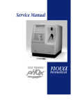
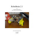
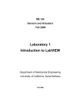
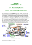
ME 104
Sensors and Actuators
Laboratory 6a
Closed Loop Analog Control
Of DC Motor Velocity
Department of Mechanical Engineering
University of California, Santa Barbara
(Rev. 2007)
Introduction
In this laboratory, you will build analog circuits on a breadboard to implement proportional (P)
and integral (I) control of a DC motor.
NOTE:
• For this lab, you will need yourname_MotorDrive_AcquireVoltage.vi which you
created for Lab 4.
• You will write ONE REPORT FOR EACH Labs 6a and 6b.
Background Reading
Please read the following material prior to this lab:
1. Histand and Alciatore, Introduction to Mechatronics, Sections 5.1-5.8 and Sections 5.10-5.11.
2. DC Motor Control Module User Manual, Pages 3-7 and 14-16, LJ Technical Systems Inc.
Experiment 1a: Open Loop Control of DC Motor Velocity
In this experiment, you will use a LabVIEW VI to drive a DC motor, similar to what you did in
Laboratory #4. You will observe both the motor drive input VIN and the tachogenerator output VOUT
(velocity feedback) on an oscilloscope.
VIN
Drive
Circuits
D/A
DC
Motor
Converter
VOUT
DAQ board
PC
Velocity
Shaft
Sensor
Rotation
DC Motor Module
Ch. 1
Ch. 2
Oscilloscope
Figure 1. Open loop control of DC motor velocity
2
In control system terminology, the system shown in Figure 1 is described as an open loop control
system. This is because the control (drive) signal VIN to your plant (the DC motor module) does not
directly (automatically) depend on the output signal VOUT. Figure 2 shows the open loop control system
in block diagram form in which the following notation has been used:
P(s) = Plant (DC Motor module) *
u = control input to VIN socket on Motor
Drive Input panel
I = Identity block (D/A Converter)
rVI = reference signal from LabVIEW VI
Tachogenerator Output panel
r = reference signal
rV I
y = plant output from VOUT socket on
r
u
Plant
y
P(s)
I
Figure 2. Open loop control block diagram
The D/A converter is represented by an identity block to indicate that the reference value seen by
your system should be equal to the reference value specified by your LabVIEW VI. For this experiment,
you will drive the DC motor such that the reference value is equal to the control input. That is, r = u.
1. Set the appropriate switches on your DC motor control module so that you can drive the motor with
analog voltage input and also obtain analog velocity feedback from the tachogenerator output.
•
MOTOR DRIVE switch: VIN position – selects analog motor drive input
•
TACHOGENERATOR switch: VOUT position – enables analog velocity feedback output
2. Use a banana connector to connect the E (Enable Input) socket to the 0V socket to enable the input
to drive the motor.
3. Connect the 0V sockets (Analog ground) on MOTOR DRIVE INPUT panel and
TACHOGENERATOR OUTPUT panel to common ground.
*
The P(s) notation indicates that the Plant is represented mathematically by its transfer function.
3
4. To drive the motor using the analog voltage output from the DAQ board, connect your motor control
module to the CB-68LP connector block according to Table 1.
Table 1. CB-68LP connector block pin assignments for open loop control of DC motor velocity.
DC Motor Control Module
VIN socket (Analog voltage) on MOTOR DRIVE INPUT panel
Connect to:
VOUT socket (Analog voltage) on TACHOGENERATOR OUTPUT panel
AO0
AI0
Ground on DC power supply*
AIGND
Ground on DC power supply*
AOGND
*The connector block can also be grounded to the breadboard if the breadboard is grounded to the DC power supply.
5. Before connecting the DC power supply to the motor module, turn ON the DC power supply and
make sure the variable output terminals are properly configured to provide –12 V and +12 V.
6. Turn OFF the DC power supply, then connect the power supply to the DC motor module.
7. Make sure that no wires or cables interfere with the moving parts of your motor.
8. Turn ON the DC Power Supply.
9. Make sure the Eddy Current Brake is disengaged. That is, make sure it is in the 0 position.
10. Connect your DC motor control module to your oscilloscope such that the reference r ( = VIN ) is
viewed on Channel 1 and the velocity feedback VOUT ( = y) is viewed on Channel 2. For best
viewing, set your vertical scales to 1volt/division and your horizontal scale to 400 ms/division.
11. Open and run yourname_MotorDrive_AcquireVoltage.vi (created for Lab 4) by clicking
the Run Continuously button. Incrementing by units of 1.00 V from -4.00 V to +4.00 V (inclusive)
for the Motor Drive Input Control, observe the voltage signals on Channels 1 and 2 of your
oscilloscope. * For each increment, make a sketch of the transient behavior and write down the steady
state † values of r and VOUT (as displayed by the digital indicators on your VI front panel).
12. Set the Eddy Current Brake to the 1 position and repeat Step 7. This brake acts as an external
disturbance to your system.
13. Set your Motor Drive Input Control to 0.00 and stop running the VI by clicking the
Abort Execution (stop) button.
*
To avoid saturation effects, the boundary reference values of [–5.00 V to 5.00 V] is reset to [-4.00 V to
4.00V].
†
“Steady state” means that you have waited long enough that transient motion has ceased.
4
Although one would like (and expect) VIN ( = y) and VOUT ( = r ) to be equal, you should have
observed that they are not equal, except when VIN = 0V. That is, your plant P(s) has a steady-state error
for nonzero reference values. In other words, in the absence of output information, the magnitude of your
plant (motor) velocity is slightly different from what you would like it to be. This situation can be
improved using closed loop (feedback) control.
Experiment 2a: Proportional (P) Control of DC Motor Velocity
In this experiment, you will use a LabVIEW VI and a proportional (P) feedback control circuit to
control a DC motor. Figure 3 shows the closed loop control system in block diagram form in which the
following notation has been used:
P(s) = Plant (DC Motor module)
e = error signal = r - y
K(s) = Controller
u = control input to VIN socket on Motor Drive
Input panel
I = Identity block (D/A Converter)
y = plant output from VOUT socket on
rVI = reference signal from LabVIEW (VI)
Tachogenerator Output panel
r = reference signal
rVI
r
I
D/A
Converter
e
+
Σ
Controller
K(s)
u
Plant
y
P(s)
-
Figure 3. Closed loop (feedback) control block diagram
Mathematically, the proportional controller can be described in the time domain as
u P (t ) = K P e(t )
where uP is the output and KP is a constant gain.
Figure 4 shows the system diagram for the closed loop control system of the DC motor.
5
r
u
D/A
Drive
Circuits
Control
Circuit
Converter
Velocity
DAQ board
y
rVI
PC
Sensor
DC
Motor
Shaft
Rotation
DC Motor Module
Ch. 1
Ch. 2
Oscilloscope
Figure 4. Closed-loop control of DC motor velocity
Note that you need to provide power to both the DC motor module and the analog circuits on the
breadboard. The DC motor module requires voltage supplies of +12 V, -12 V, +5 V, and ground.
The analog circuits include LMC6484 op-amps which require voltage supplies of V+ = 5 V and V- = 5 V. Since the DC power supply at each station has only three output terminals and four different
voltage outputs (+12 V, -12 V, +5 V, and –5 V) are needed, an L7905ACV negative voltage regulator
is used to convert the -12V signal from the power supply to –5 V for the op-amp.
2
VIN = -12 V
0.1 μF
L7905ACV 3
IN
VOUT = - 5 V
OUT
GND
1
(a)
0.1 μF
L7905ACV
WK0040342
CHINA
Build the voltage regulator circuit, shown in Figure 5. Follow the wire color scheme in Table 2.
3 – OUTPUT
2 – INPUT
1 – GROUND
(b)
Figure 5. (a) Voltage regulator circuit.
(b) Pin assignment for L7905ACV negative voltage regulator.
6
Table 2. Wire color scheme
Wire color
Red
Purple
White
Green
Black
Voltage
+12 V
-12 V
+5 V
-5 V
0 V (Ground)
1. Using a voltmeter, verify that the output voltage of the voltage regulator circuit is –5 V.
2. Build the proportional control (p-control) circuit, shown in Figure 6 . Two LMC6484 op-amps
have been pre-inserted on your breadboard. Build the p-circuit on the LEFT op-amp on the
breadboard. Pin assignments for the op-amp are shown in Figure 7. Remember to provide
positive power (V+ = 5V from “5V FIXED 3A” terminal on power supply) to Pin 4 and negative
power (V- = -5V from voltage regulator circuit) to Pin 11 * . Choose your resistors such that R =
100 kΩ and RF = 4.7 MΩ. Then,
KP = 1+
RF
= 48 .
R
2
1
Figure 6. Proportional control circuit. The circuit consists of a difference amplifier (that
calculates the error) followed by a noninverting amplifier that multiplies the error by
a constant gain KP. (Note: Power supply connections are not shown for clarity.)
*
As a safety precaution, use your voltmeter to verify the values of your positive and negative supply voltages.
7
Figure 7. LMC6484 op-amp connection diagram
3. Connect the reference signal r from AO0 (Analog Output 0) to the proportional control circuit as
shown in Figure 6.
4. To drive the motor using the proportional control signal uP from the proportional control circuit,
connect your motor control module and proportional control circuit to the CB-68LP connector
block according to Table 3.
Table 3. CB-68LP connector block pin assignments for proportional control of DC motor
velocity.
DC Motor Control Module
Connect to:
VIN socket (Analog voltage) on MOTOR DRIVE INPUT panel
P feedback circuit output (uP
connection).
VOUT socket (Analog voltage) on TACHOGENERATOR OUTPUT
panel
AI0 and P feedback circuit input
(y connection).
5. Retain the ground connections from Experiment #1a.
6. Retain your oscilloscope connections from Experiment #1a. That is, connect your DC motor
control module to your oscilloscope such that the reference r (AO0) is viewed on Channel 1 and
the velocity feedback y = VOUT (AI0) is viewed on Channel 2.
7. Make sure the Eddy Current Brake is disengaged. That is, make sure it is in the 0 position.
8
8. Run yourname_MotorDrive_AcquireVoltage.vi (from Lab 4) by clicking the Run
Continuously button. Increment the Motor Drive Input Control by 1V from –4.00 V
to 4.00 V, inclusive, and observe the voltage signals on Channels 1 and 2 of your oscilloscope.
Make a sketch of the transient behavior and write down the steady state values of r and y (as
displayed by the digital indicators on your VI front panel).
9. Set the Eddy Current Brake to the 1 position and repeat Step 5.
10. Set your Motor Drive Input Control to 0.00 and stop running the VI by clicking the
Abort Execution (stop) button.
Although the velocity signal y ( = VOUT ) is closer to the reference value r than in the open loop
case (Experiment #1), the two signals are still unequal. In other words, tracking has improved, but
your plant P(s) still shows a steady-state error for nonzero reference values. This steady-state error
can be eliminated using closed loop integral control.
Experiment 3a: Integral (I) Control of DC Motor Velocity
In this experiment, you will use a LabVIEW VI and an integral feedback control circuit to
control a DC motor as shown in Figures 3 and 4. Mathematically, the integral (I) controller can be
described in the time domain as
t
u I (t ) = K I ∫ e(η )dη
0
where uI is the output and KI is a constant gain.
1. Use the two remaining op-amps on the left LMC6484 chip to build the integral control circuit
shown in Figure 8. Provide the error input (e) to this circuit from the (first half of the) circuit you
built in Experiment #2a. Choose your resistors and capacitor such that R = 100 kΩ, RF = RI = 1
MΩ, and C = 0.1 μF. Then,
⎛
1 ⎞⎛ RF ⎞
⎟⎟⎜ −
K I = ⎜⎜ −
⎟ = 100 .
⎝ RI C ⎠⎝ R ⎠
9
I
3
4
Figure 8. Integral control circuit. This circuit consists of an integrator (that calculates the error
integral) followed by an inverting amplifier that multiplies the error integral by a
constant gain KI. . (Note: Power supply connections are not shown for clarity.)
2. To drive the motor using the integral control signal uI from the feedback control circuit, connect
your motor control module and feedback circuit to the CB-68LP connector block as shown in
Table 4.
Table 4. CB-68LP connector block pin assignments for integral control of DC motor velocity.
DC Motor Control Module
Connect to:
VIN socket (Analog voltage) on MOTOR DRIVE INPUT panel
I feedback circuit output (uI
connection).
VOUT socket (Analog voltage) on TACHOGENERATOR OUTPUT
panel
AI0 and feedback circuit input
(y connection).
3. Retain the ground connections.
4. Retain your oscilloscope connections from Experiment 1a. That is, connect your DC motor
control module to your oscilloscope such that the reference r (AO0) is viewed on Channel 1 and
the velocity feedback y = VOUT (AI0) is viewed on Channel 2.
5. Make sure the Eddy Current Brake is disengaged. That is, make sure it is in the 0 position.
6. Open and run yourname_MotorDrive_AcquireVoltage.vi by clicking the Run
Continuously button. Increment your Motor Drive Input Control by 1V from -4.00 V
to +4.00 V, inclusive, and observe the voltage signals on Channels 1 and 2 of your oscilloscope.
Make a sketch of the transient behavior and write down the steady state values of r and VOUT as
displayed by the digital indicators on your VI front panel.
10
7. Set the Eddy Current Brake to the 1 position and repeat Step 5.
8. Set your Motor Drive Input Control to 0.00 and stop running the VI by clicking the
Abort Execution (stop) button.
Your plant P(s) should show zero steady-state error for all reference values. However, this has
been achieved at a price. Namely, your system experiences transient oscillations that you did not
observe previously. In other words, although the velocity signal y = VOUT will equal the reference
value r after a sufficient amount of time has passed, the velocity has a tendency to overshoot its
intended target at the onset. By combining proportional and integral control, the (desired) zero
steady-state error condition can be maintained, but with significantly reduced overshoot. You will
investigate in next week’s lab. Retain your P and I control circuits for next week’s lab.
Laboratory Report
1. For the VI’s you used in this laboratory, provide a printout that shows the front panel and block
diagram.
2. Using the data you collected with the Eddy Current Brake in the 0 position, provide a graph of
steady-state velocity (voltage) output y versus reference (voltage) signal r * for the following
control methods: (a) open loop, (b) proportional, and (c) integral. For comparison, all three
control methods should be plotted on the same graph. Clearly indicate which plot corresponds to
which control method and compare the steady-state performance of the different control methods.
3. Repeat Question 2 for the data you collected with the Eddy Current Brake in the 1 position. Is
there a notable difference between your plots in Question 2 and Question 3? Explain.
4. Using the observations you made with the Eddy Current Brake in the 0 position, provide a
sketch of your DC motor’s transient behavior. All three control methods should be shown on the
same sketch (graph) for comparison. Compare the transient behavior of each of your control
methods.
5. Repeat Question 4 for the observations you made with the Eddy Current Brake in the 1
position.
*
Your x-axis should consist of the values r = [ -4, -3, -2, -1, 0, 1, 2, 3, 4 ], with units in volts.
11
Your Lab Report should clearly state your name, Lab Report number, Lab date, and your
laboratory partner’s name (if any). Your lab report should be thorough, but concise. You will be
graded on quality, not quantity. Lab Report #6a is due at the beginning of Laboratory #6b.
12