1
USER GUIDE
u-line.com
SAFETY • INSTALLATION & INTEGRATION • OPERATING INSTRUCTIONS • MAINTENANCE • SERVICE
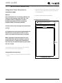
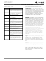
4. Remove the unit. Using a square, extend center line
5. Place the anti-tip brackets on the floor against the line
“B” (see chart below). This line serves as the back
drawn for the outer edge. Mark spots for the screw
edge for the anti-tip brackets. From the center line,
holes.
measure “A” to the left and right. This line is the outer
edge of each bracket.
Surrounding
area (Top view)
Surrounding
area (Top view)
Drill holes and
mount anti-tip
brackets to floor
Back of unit
Back wall
Back wall
B
Front
of
unit
A
B
Back
of
unit
A
A
CL
A
CL
Front of unit
1024/1224 WC
1215 WC
A
11-1/16" (281 mm)
6-9/16" (167 mm)
B
20-1/4" (514 mm)
20-1/4" (514 mm)
1024/1224 WC
1215 WC
A
11-1/16" (281 mm)
6-9/16" (167 mm)
B
20-1/4" (514 mm)
20-1/4" (514 mm)
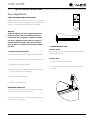
6. Use a 1/8" drill to make two starter holes and fasten
the anti-tip brackets to the floor using the screws
provided.
7. Place the unit back into position, making sure the feet
engage the anti-tip brackets properly. Check the
alignment of the lines made on the floor in step 3 with
the position of the front feet to ensure proper
positioning.
Anti-Tip Bracket 2